A Textron C~ompany Wiring Diagram Manual MODEL 206H/T206H 1997 SERIAL 20608001 AND ON SERIAL T20608001 AND ON 11*11 Member of GAMA COPYRIGHT " 1997 CESSNA AIRCRAFT COMPANY WICHITA, KANSAS, USA 3 NOVEMBER 1997 206HWD05 Revision 5 ~~~1 January 2007 Revision 5 206HWD05
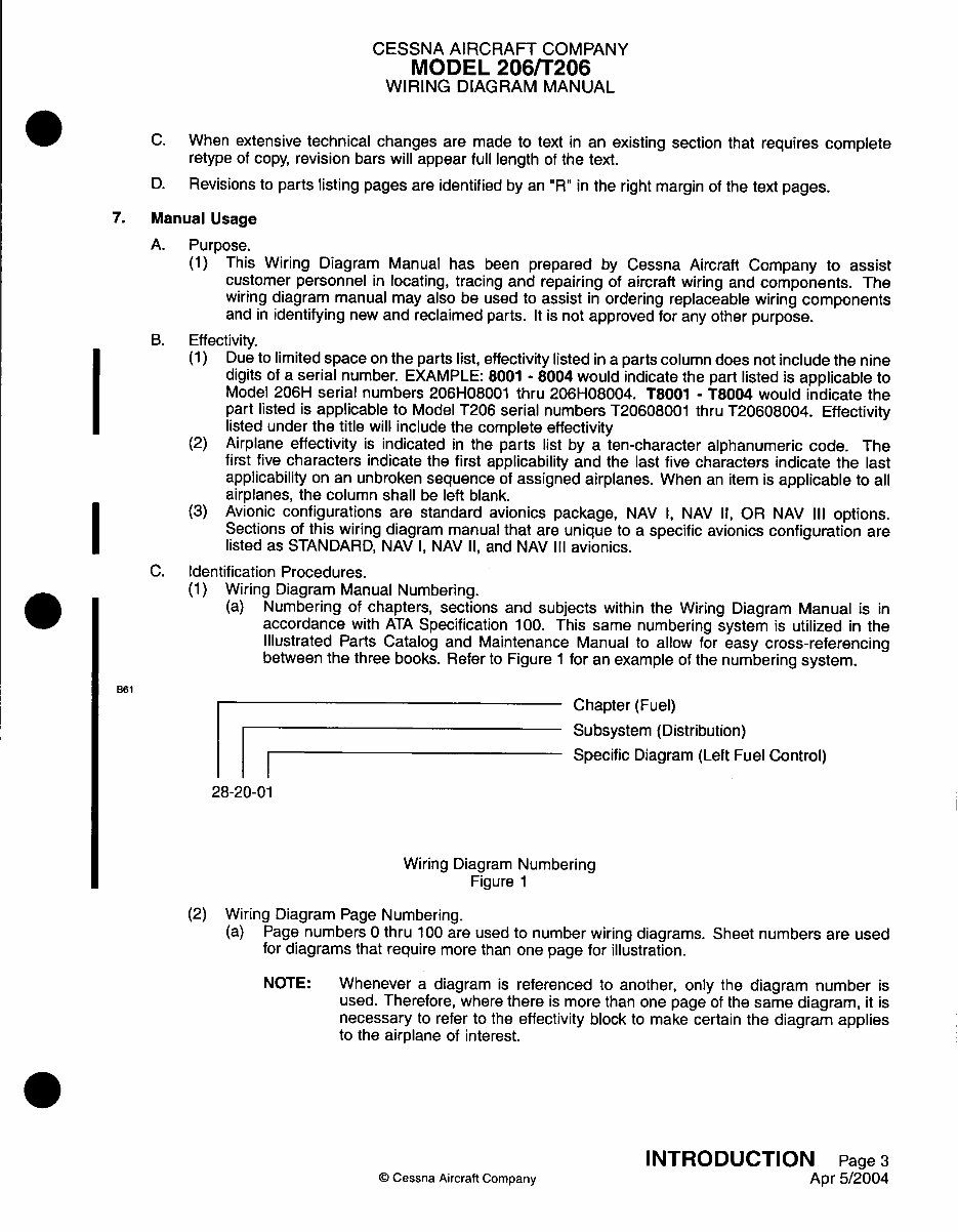
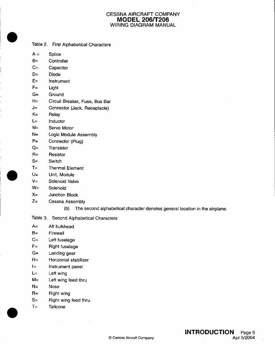
CESSNA AIRCRAFT COMPANY MODEL 206/T206 WIRING DIAGRAM MANUAL Table 3. Second Alphabetical Characters (continued) V= Vertical stabilizer Z= Inside a Cessna Assembly (c) The three (3) numeric characters are sequentially assigned and do not denote location or order of occurrence. F List of Chapters. (Paper version of this manual only.) * ~~(1) The List of Chapters includes all chapters used in this manual. G. Alphabetical Indexes. (Paper version of this manual only.) (1) The Alphabetical Index lists all subjects in this manual. I ~ ~(2) The Component Index is an alphabetical list of components in this manual. H. Reference Designator Index (Paper version of this manual only.) (1) The Reference Designator Index is a complete listing of all reference designators included in the parts list. All reference designators are cross-referenced to the part number and applicable I ~ ~~~chapter, section, subject and figure where the reference designator is used. I. Part Number Indexes. (Paper version of this manual only.) (1) The Part Number Index is a complete listing of all parts included in the parts list. All part numbers are cross-referenced to the reference designator and applicable chapter, section, subject and I ~ ~~~figure where the part number is used. J. Chapter 20 Includes. (1) Safety precautions. (2) General maintenance information for wire repairs, grounding of wires, soldering, heat shrink tubing, resistors, torque values, connectors, and relay sockets. (3) Information on connectors for removal and installation of contacts, contact pin and socket part numbers, tools to crimp the contacts, sealing of potted type connectors and connector contact arrangements. K. Chapter 91 Includes. (1) Reference information for connectors, ground locations and component locations. (a) Connector charts are provided for those connectors that contain wires for several different systems. All contact pins are shown for the complete connector. The wire number for each wire to a pin is shown with reference to the system where the complete circuit will be found. (b) Ground locations are provided for all grounds. (c) Component location charts are provided listing each reference designator and its location in the airplane. L. How To Use This Manual. (1) All operable electrical components, such as relays, etc., are shown with the airplane on the ground, all circuits off or de-energized and no electrical power on the circuits. Switches are shown in the off or normal position unless otherwise noted. (2) The parts list may consist of two or more text lines. Make certain that all lines are observed, as the part number and part description are not always complete on the first line. (3) Some wire diagrams have too many parts to list on one page of text. In this case, identical wire diagrams are used with a different parts list for each diagram. (4) Letters or numbers are used to identify the contacts of a connector to which each wire is connected. (a) The letter or number shown on the wiring diagram is also marked on the connector. (b) A letter that is underlined or preceded by an asterisk indicates a lower case letter. On wire diagrams, the letter may be printed in either lower case or capital letters, but both indicate lower case on the connector. INTRODUCTION Page 6 C Cessna Aircraft Company Apr 5/2004
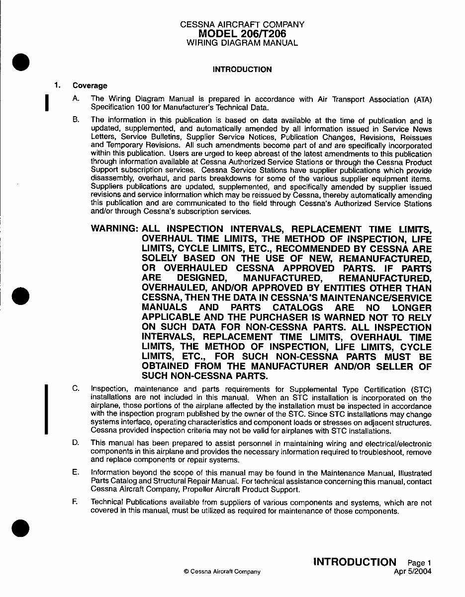
The 1997-2007 Cessna 206H, T206H Wiring Diagram Manual (Revision 5) is the official Textron Aviation electrical schematic reference for the Cessna 206H and turbocharged T206H aircraft. It includes detailed wiring diagrams for all major systems, ideal for avionics troubleshooting, electrical diagnostics, and maintenance planning.
This manual is essential for A&P mechanics, avionics technicians, and FAA-certified repair stations requiring precise information on the aircraft’s electrical systems. With factory-accurate wiring paths, component locations, and connector pinouts, it ensures compliance and accuracy during inspection and repair procedures.
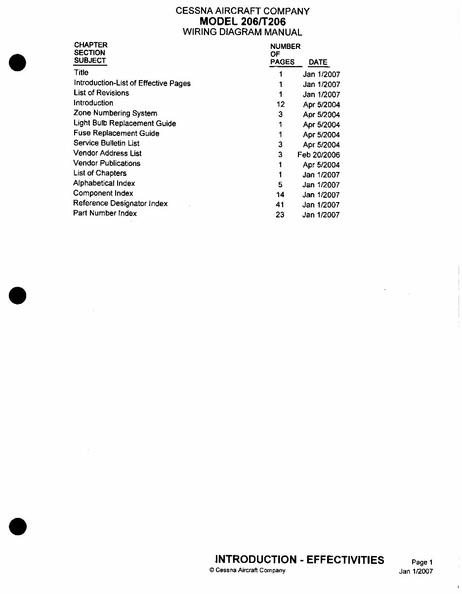
Content Overview:
Complete aircraft electrical schematics for 206H and T206H
Wiring diagrams for lighting, avionics, environmental systems, and more
Connector pin assignments and terminal identification
Component location illustrations and symbol key
Serial number applicability annotations
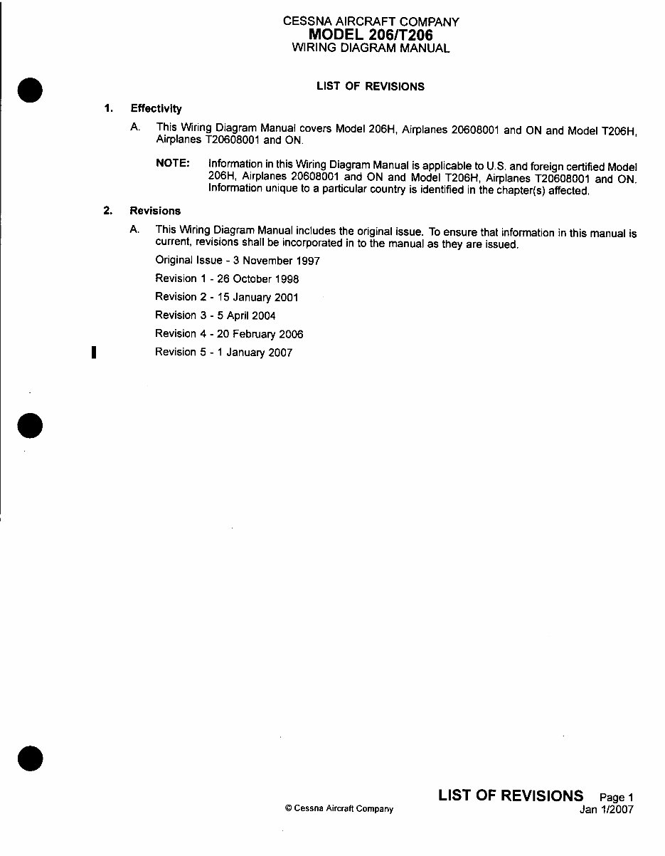
Revision record from 1997 through 2007
Whether you’re troubleshooting a power distribution issue or installing new avionics, this wiring diagram manual delivers the OEM data needed for confident and airworthy electrical work.
Regulatory Note: This manual applies to U.S. and foreign certified aircraft. Revisions and supplements are included to address model changes up to January 2007. All country-specific differences are called out within the relevant chapters. This version is Revision 5, dated 1 January 2007.
Printable: Yes Language: English Compatibility: Pretty much any electronic device Requirements: Adobe Reader (free)