A Textron Company
Illustrated Parts Catalog
MODL 72 &
MOE 12
REVISION 15 INCORPORATES TEMPORARY REVISION 172RPC14TR80-1 DATED 13 FEBRUARY 2007
Member of GAMA
COPYRIGHT©1997
CESSNA AIRCRAFT COMPANY
WICHITA, KANSAS, USA
172 RPC 15
2 DECEMBER 1997
REVISION 15 1 JULY 2007
CESSNA AIRCRAFT COMPANY
MODEL 172
ILLUSTRATED PARTS CATALOG
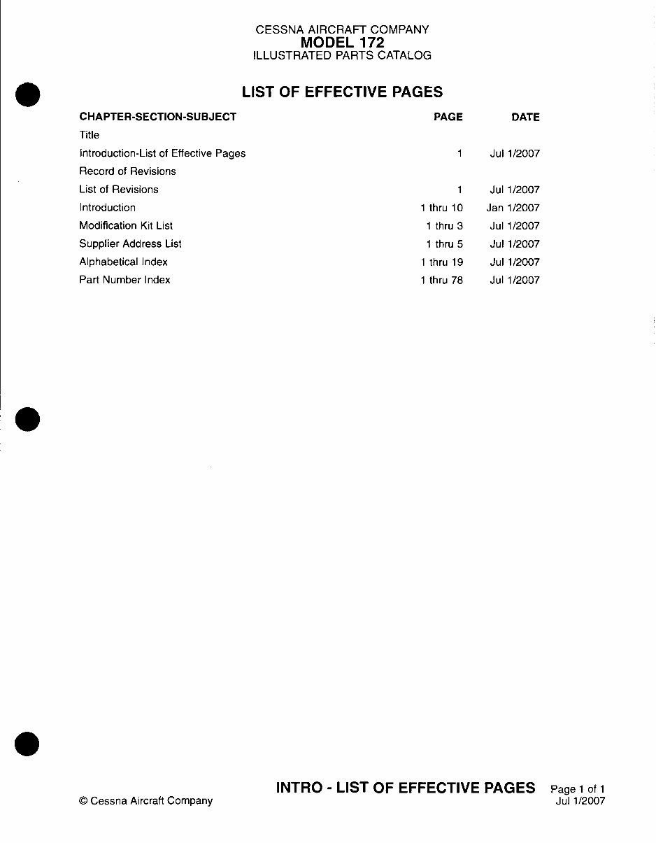
LIST OF EFFECTIVE PAGES
CHAPTER-SECTION-SUBJECT
Title
Introduction-List of Effective Pages
Record of Revisions
List of Revisions
Introduction
Modification Kit List
Supplier Address List
Alphabetical Index
Part Number Index
© Cessna Aircraft Company
PAGE DATE
1 Jul 1/2007
1 Jul 1/2007
1 thru 10 Jan 1/2007
1 thru 3 Jul 1/2007
1 thru 5 Jul 1/2007
1 thru 19 Jul 1/2007
1 thru 78 Jul 1/2007
INTRO - LIST OF EFFECTIVE PAGES Page 1 of 1
Jul 1/2007
CESSNA AIRCRAFT COMPANY
MODEL 172
ILLUSTRATED PARTS CATALOG
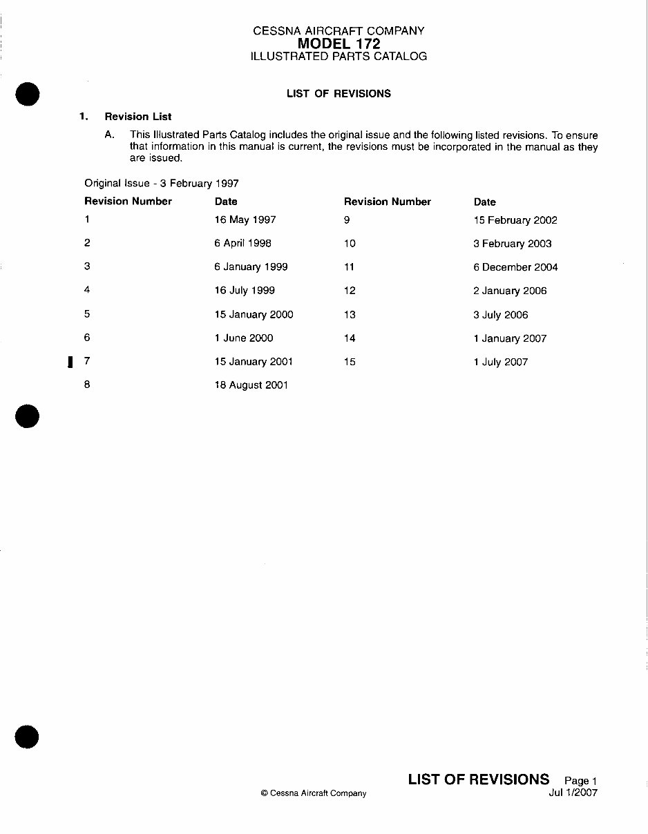
LIST OF REVISIONS
1. Revision List
A. This Illustrated Parts Catalog includes the original issue and the following listed revisions. To ensure
that information in this manual is current, the revisions must be incorporated in the manual as they
are issued.
Original Issue - 3 February 1997
Revision Number Date Revision Number Date
1 16 May 1997 9 lS February 2002
2 6 April 1998 10 3 February 2003
3 6 January 1999 11 6 December 2004
4 16 July 1999 12 2 January 2006
5 l5 January 2000 1 3 3 July 2006
6 1 June 2000 14 1 January 2007
37 15 January 2001 1 5 1 July 2007
8 18 August 2001
Cessna Aircraft Company
LIST OF REVISIONS Page 1
Jul 1/2007
CESSNA AIRCRAFT COMPANY
MODEL 172
ILLUSTRATED PARTS CATALOG
DATE DATE
INSERTED REMOVED
PAGE
NUMBER
REVISION
NUMBER
RECORD OF REVISIONS
DATE DATE PAGE
INSERTED REMOVED NUMBER
REVISION
NUMBER
CESSNA AIRCRAFT COMPANY
MODEL 172
ILLUSTRATED PARTS CATALOG
INTRODUCTION
1.General
A. The purpose of this Illustrated Parts Catalog is to illustrate and identify replacement parts and
assemblies necessary for the support of the model covered herein. The information in the catalog
is based on data available at the time of publication. DO NOT USE this Illustrated Parts Catalog
to determine removal and installation procedures, refer to the Maintenance Manual. The airplane
operator, using applicable rules, is responsible for determining the status (or airworthiness) of the
airplane.
B. Chapter 11 contains procurable placards. Placards required by particular countries, determined by
foreign certification authorities, are segregated into groups identified by International Civil Aviation
Organization (ICAO) two-letter identifier located in the page footer. Cessna recommends all placards
be present and readable on the airplane.
C. Placards identified by the Code of Federal Regulations (CFRs) include: cockpit information
including instrument markings and any related
limitations, aircraft operating limitations, powerplant
and auxiliary power unit instruments, flight control markings, fuel, oil, door and emergency exit
information, limitations on storage compartments, loading, passenger cabin safety, and safety
equipment operation.
D. This Illustrated Parts Catalog is divided into chapters which correspond to equivalent chapters in
the Maintenance Manual and is prepared in accordance with the Air Transport Association 2200
Specification format.
E. The information in this publication is based on data available at the time of publication and is updated,
supplemented, and automatically amended by Service Bulletins, Publication Revisions, Reissues, and
Temporary Revisions which are issued through subscriptions service available from Cessna Propeller
Aircraft Product Support. All such amendments become part of and are specifically incorporated within
this publication. Users are urged to keep abreast of the latest amendments to this publication through
Cessna Propeller Aircraft Product Support subscription services and/or Cessna Authorized Service
Stations. Cessna Propeller Aircraft Product Support may be contacted by phone at (316)517-5800 or
fax at (316)517-7271 or (316)942-9006, or in writing at 2121 S. Hoover Wichita, KS 67209.
WARNING: ALL INSPECTION INTERVALS, REPLACEMENT TIME LIMITS,
OVERHAUL TIME LIMITS, THE METHOD OF INSPECTION, LIFE
LIMITS, CYCLE LIMITS, ETC., RECOMMENDED BY CESSNA ARE
SOLELY BASED ON THE USE OF NEW, REMANUFACTURED,
OR OVERHAULED CESSNA APPROVED PARTS. IF PARTS
ARE DESIGNED, MANUFACTURED, REMANUFACTURED,
OVERHAULED, ANID/OR APPROVED BY ENTITIES OTHER
THAN CESSNA, THEN THE DATA IN CESSNA'S MAINTENANCE/
SERVICE MANUALS AND PARTS CATALOGS ARE NO LONGER
APPLICABLE AND THE PURCHASER IS WARNED NOT TO RELY
ON SUCH DATA FOR NON-CESSNA PARTS. ALL INSPECTION
INTERVALS, REPLACEMENT TIME LIMITS, OVERHAUL TIME
LIMITS, THE METHOD OF INSPECTION, LIFE LIMITS, CYCLE
LIMITS, ETC., FOR SUCH NON-CESSNA PARTS MUST BE
OBTAINED FROM THE MANUFACTURER AND/OR SELLER OF
SUCH NON-CESSNA PARTS.
F. Inspection, maintenance and parts requirements for Supplemental Type Certification (STC)
installations are not included in this catalog. When an STC installation is incorporated on the
airplane, those portions of the airplane affected by the installation must be inspected in accordance
INTRODUCTION Page 1
© Cessna Aircraft Company
Janl1/2007
CESSNA AIRCRAFT COMPANY
MODEL 172
ILLUSTRATED PARTS CATALOG
with the inspection program published by the owner of the STC. Since STC installations may change
systems interface, operating characteristics and component loads or stresses on adjacent structures,
Cessna provided inspection criteria may not be valid for airplanes with STC installations.
2. Effectivity
A. Numbers in the effectivity column indicate usage of the part is restricted. For example, the numbers
0001 in the Effect From column and 0023 in the Effect To column indicate that the part is used on
airplanes 1 thru 23. If this column is blank opposite a first column listing of the figure, the usage
is applicable to all models and serials covered by this catalog. If this column is blank opposite any
indented listing, the usage is applicable to all models and serials covered by the next higher assembly
or assemblies under which it appears.
NOTE: Information in this Illustrated Parts Catalog is applicable to U.S. and Foreign Certified
airplanes. Information unique to a particular country is identified in the chapter(s) affected.
3. Aerofiche
A. The Illustrated Parts Catalog has been designed for Aerofiche presentation. Refer to the header of
the applicable fiche for location of various indexing information.
4. Compact Disc (CD-ROM)
A. Publications for this model are available in paper and as electronic media CD-ROM (Compact Disc
- Read Only Memory). The paper publications are available as individual publications, such as
Maintenance Manual, Illustrated Parts Catalog, etc., while the electronic service publications are
grouped together on the CD. One CD includes all the service publications (Maintenance Manual,
Illustrated Parts Catalog, Wiring Diagram Manual, Component Maintenance Manual, Nondestructive
Testing Manual, Structural Repair Manual, and Illustrated Tools and Equipment List and all the
Service Bulletins). These publications are kept up-to-date through routine revisions.
5. Part Number Index (Paper and Aerofiche)
A. Part numbers in the Part Number Index are arranged in order according to the extreme left digit, then
the next digit to the right, etc. The digits are used in the following sequence: space, symbols (such
as #), decimal, slash (I), numbers in numerical order, then letters of the alphabet.
B. The Part Number Index is a complete listing of all parts included in the Detailed Parts List.
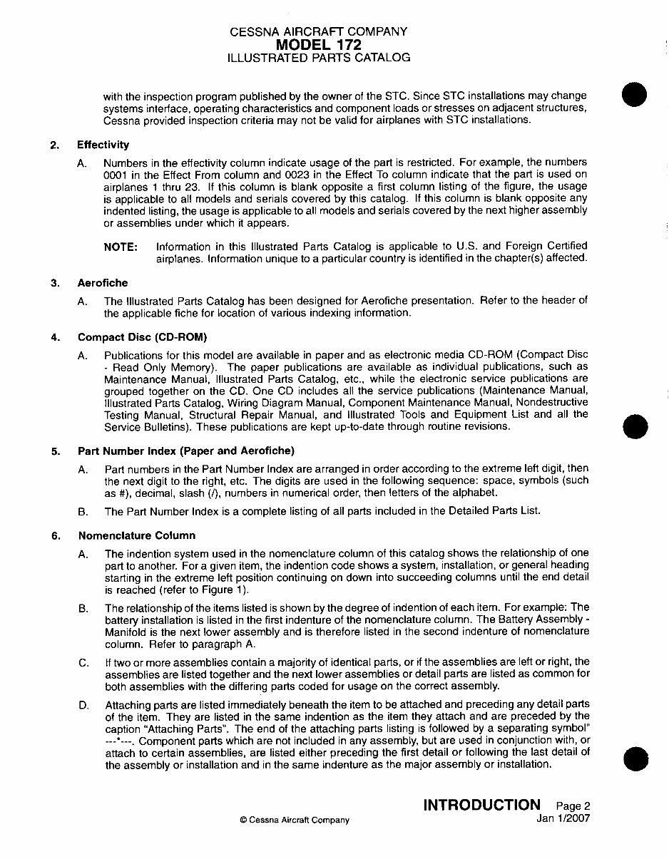
6. Nomenclature Column
A. The indention system used in the nomenclature column of this catalog shows the relationship of one
part to another. For a given item, the indention code shows a system, installation, or general heading
starting in the extreme left position continuing on down into succeeding columns until the end detail
is reached (refer to Figure 1).
B. The relationship of the items listed is shown by the degree of indention of each item. For example: The
battery installation is listed in the first indenture of the nomenclature column. The Battery Assembly -
Manifold is the next lower assembly and is therefore listed in the second indenture of nomenclature
column. Refer to paragraph A.
C. If two or more assemblies contain a majority of identical parts, or if the assemblies are left or right, the
assemblies are listed together and the next lower assemblies or detail parts are listed as common for
both assemblies with the differing parts coded for usage on the correct assembly.
D. Attaching parts are listed immediately beneath the item to be attached and preceding any detail parts
of the item. They are listed in the same indention as the item they attach and are preceded by the
caption "Attaching Parts". The end of the attaching parts listing is followed by a separating symbol"
-- -- Component parts which are not included in any assembly, but are used in conjunction with, or
attach to certain assemblies, are listed either preceding the first detail or following the last detail of
the assembly or installation and in the same indenture as the major assembly or installation.
INTRODUCTION Page 2
© Cessna Aircraft Company Janl1/2007
CESSNA AIRCRAFT COMPANY
MODEL 172
ILLUSTRATED PARTS CATALOG
B1515
1 2 3 4 5 6 7
Installation
* Detailed Parts for Installation
* Assembly
* Attaching Parts for Assembly
* ~~Detailed Parts for Assembly
* . Sub-Assembly
* . Attaching Parts for Sub-Assembly
* ~~~Detailed Parts for Sub-Assembly
* . ~Sub-Assembly
* . . ~Attaching Parts for Sub-Assembly
* . ~~~Detailed Parts for Sub-Sub-Assembly
Order of Assembly
Figure 1
7. List of Effective Pages (Paper and Aerofiche Versions)
A. A List of Effective Pages is provided in the front of each chapter of the catalog. All pages in the catalog
are listed in sequence on the List of Effective Pages with the most recent revision date for each page.
A revised List of Effective Pages is provided for every Illustrated Parts Catalog revision.
8. Revision Filing Instructions (Paper Version)
A. Regular Revision.
(1) Refer to the List of Effective Pages of each chapter while inserting a revision.
(2) Pages changed by the revision will be indicated by the revision date on the page and on the List
of Effective Pages for that chapter. The revised page replaces the existing page in the catalog.
(3) Existing pages no longer needed in the catalog are indicated by "Deleted" on the List of Effective
Pages. These pages are to be removed and discarded. When a page has been deleted by a
revision, the List of Effective Pages for subsequent revisions do not list the page.
B. Temporary Revisions.
(1) File Temporary Revisions in the applicable chapter in accordance with the filing instructions on
the first page of the Temporary Revision.
(2) Temporary Revisions should be removed from the catalog only when replaced by a revision to
the catalog or by instructions noted on the superseding Temporary Revision.
9. Revision Indicators
A. Additions or revisions to the parts list will be identified by the letter "R" in the right margin of the page
adjacent to the change or addition. When technical changes cause unchanged text to appear on a
different page, an "R" will be placed in the margin opposite of the affected items.
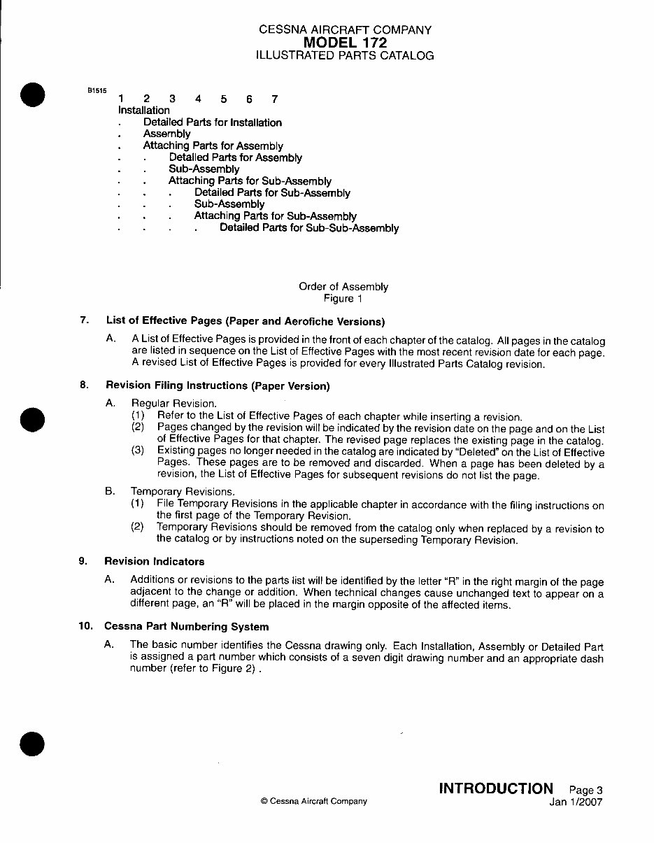
10. Cessna Part Numbering System
A. The basic number identifies the Cessna drawing only. Each Installation, Assembly or Detailed Part
is assigned a part number which consists of a seven digit drawing number and an appropriate dash
number (refer to Figure 2)
© Cessna Aircraft Company
INTRODUCTION Page 3
Janl1/2007
CESSNA AIRCRAFT COMPANY
MODEL 172
ILLUSTRATED PARTS CATALOG
B1518
Basic Number
(Drawing Identification
Only)
Part Number
0553031 -1
Dash Number
Part Number System
Figure 2
11. Standard Parts
A. Many parts having standard usage have been incorporated into the Cessna Standard System. Parts
in this group are designated with the part number prefix "5", "CM", or "C".
B. For standard hardware items such as screws, nuts, clamps, etc., AN, NAS, and MS standard numbers
are listed.
12. Page Numbering System
A. The Page Numbering System used in the Illustrated Parts Catalog consists of three-element numbers
separated by a dash with the figure number, page number and date printed to the side (refer to Figure
3).
Chapter/System
(Flight Controls)
Subject/Subsystem
(Aileron System)
Subject/Unit
(Ailerons)
Figure 01 - Figur
27-10-00
Page Numbering System
Figure 3
13. Part Number Column
A. This column contains the manufacturer's part number used to identify the item.
14. Units Per Assembly Column
A. The quantity listed in the Units Per Assembly column is the quantity used per item. The quantity
listed for attaching parts denotes the quantity necessary to attach only one item. The total quantity
necessary to attach more than one item may be obtained by multiplying the quantity of attaching parts
by the number of items to be attached.
15. Symbols and Part Number Terms
A. When the term, "REFER TO", appears in the Nomenclature column and the Units Per Assembly
column indicates "RF", the figure referred to will be the next highest assembly of the referred item.
INTRODUCTION Page 4
© Cessna Aircraft Company Janl1/2007
B1518
'e Number
0nnn _-4
r-awoV - FI Q U VO0 VJI
Dec 2/96 Aileron System
I .. Date of Page Issue
CESSNA AIRCRAFT COMPANY
MODEL 172
ILLUSTRATED PARTS CATALOG
B. When the term, "DELETED-NOT USED", appears in the Nomenclature column, it signifies that the
index number was used but is no longer required. This procedure is used to eliminate re-indexing of
all items following the deleted part.
C. When the letters BKI (Bulk Item) appear in the Nomenclature column and the units per assembly
column indicates "AR" (As Required). refer to Cessna Service Parts Center for prices and units of
measure.
16. Abbreviations Commonly Used
ALT alternate
IPC illustrated parts catalog
AR as required
NP non-procurable
ASSY assembly
RE reference
BKI bulk item
SB service bulletin
FSO for spares order
TR temporary revision
17. Serial and Color
A. When ordering upholstery material, carpet, or interior trim, include airplane model and serial number.
Model and serial number are important to assure that the correct color combination is received.
18. Modification Kits
A. A record of Modification Kits and Service Bulletins are provided in the Modification Kit List section.
B. The Modification Kits List provides the kit number, title, date the kit was issued, Service Bulletin or
applicable document number, and catalog incorporation date.
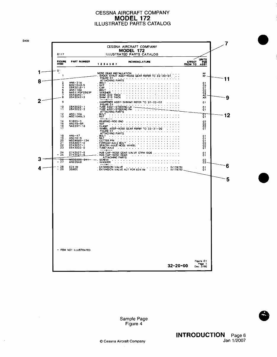
19. Definition of Text Page Information
A. Refer to Figure 4.
(1) The figure number refers to the corresponding illustration.
(2) The number in the Figure and Item Number column corresponds to the item number of the part
in the corresponding illustration.
(3) Attaching parts are listed immediately following the part(s) attached. The symbol -- *- follows
the last item of the attaching parts.
(4) Parts with the item number preceded by a dash are not indexed on the illustration.
(5) A Supplier's part number is identified in the Part Number column and the federally supplied
vendor code follows the nomenclature in the Nomenclature column.
(6) A number in the Units Per Assembly column indicates the quantity of the part used per next
higher assembly or installation.
(7) Numbers in the Effectivity column indicate usage of the part is restricted. For example, the
numbers 0001 0023 indicate that the part is used on airplanes 1 thru 23.
(8) This cross-reference indicates the figure in which the installation of assembly is broken down to
its component parts.
(9) Parts with the quantity "as required" are indicated by "AR" in the Units Per Assembly column.
(1 0) Alternate part numbers are listed immediately following the part for which they may be
substituted. The entry "ALT FOR" will be shown in the Nomenclature column.
(11) "RF" indicates the installation or assembly is listed again in the figure cross-referenced in the
Nomenclature column. The Units Per Assembly is given in the referenced figure.
(12) Parts used only on a left or right installation or assembly are designated by "LH" or "RH" in the
Nomenclature column.
(13) A "USED ON" or "USED WITH" note in the Nomenclature column indicates the next proper
higher assembly of a part when the part is not common to all of the next higher assemblies listed
preceding the part.
(14) The letter "R" in the right margin indicates text added or revised by the latest catalog revision.
INTRODUCTION Page 5
© Cessna Aircraft Company
Janl1/2007
CESSNA AIRCRAFT COMPANY
MODEL 172
ILLUSTRATED PARTS CATALOG
CESSNA AIRCRAFT COMPANY
MODEL 172
0117 ILLUSTRATED PARTS CATALOG
~XNTS
FIGURE PART NtJMIER NOMENCLATURE EFFECT PER
ITEM 1 234 5 67 FROM TO ASSY
-01
- ~~~~~NOSE GEAR INSTALLATION . ... RF
1 .SHOCK STRUT ASSY-NOSE GEARREFER TO032-20-01.. RF-
FIGURE 0 1 ......................
ATTACHING PARTS
2 AN5-31A S OLT ......................... 0 1
3 MS21042L_5 .NUT. ........................ 03
4 0543018-I CAP. ........................ 01
5 AN5-10A BOLT. ........................ 02
6 NAS1149F0563P .WASHER .............. I III 02
7 0543042-1 .SHIM .032 THICK. .................. AR-
a- 0543042-2 .SHIM .0 16 THICK .................... AR
9 .DAMPENER ASSY-SHIMMY REFER TO 32-20-02 ..... 01
FIGURE 0 1 ......................
10 0543022-1 .TUBE ASSY-STEERING LH 01
11 0543022-2 TUBE ASSY-STEERING RH..0
ATTACHING PARTS
12 ANJ3-10A .BOLT .............. . ..... 1
13 MS21045L3 .NUT..01
14 S 1823-3 . BEARING-ROD END ............ .02
15 AN316-6R NUT .............. ..... 02
16 NAS397-16 CLAMP 02
17 WHEEL AgSS~-N6s GEARi REFER TO3 32-31i-00 01
FIGURE 01 ...
ATTACHING PARTS
15 AN5-47 .BOLT ............... .......... 01
19 AN310-5 .NUT .... .01. .
20 MS24665-134 .COTTER PIN.:::::::::. ::::.. :01
21 0543001-0 .FERRULE-AXLE BOLT .......... .02.. ..
22 0543037-1 .SPACER-AXLE NOSE WHEEL ........ . .. 02
23 0543003-0 .TUBE-AXLE ............. ...... 01
24 0743627-5 .HUB CAP-NOSE GEAR VALVE STEM SIDE. .... 01
- 25 0743627-5 . ~HUB CAP-NOSE GEAR. ................ 01
____ ___ ____ ___ ____ ___ ATTACHING PARTS
- - ---- 41 SCREW. ....................... 03
-27 AN936A5 WASHER. ...................... 03 -
-- 213 6241M EXTENSION VALVE. .............. (V 17875) 01
- 29 3680C .EXTENSION VALVE ALT FOR 624 M ....... I(Vi 7875) 01
- ITEM NOT ILLUSTRATED
Figure 0 1
32-20-00 Dec "2g19 6
Sample Page
Figure 4
© Cessna Aircraft Company
INTRODUCTION Page 6
Janl1/2007
B409
1 -
8-
2--
4 -
7
_11
___ 9
- 12
-- -6
-5
You're Reading a Preview
What's Included?
Lifetime Access
Access PDF Contents & Bookmarks
Print one or all pages of your manual