Beechcraft Bonanza 35 thru G35 IPC Parts Catalog Manual -
What's Included?
Lifetime Access
Fast Download Speeds
Online & Offline Access
Access PDF Contents & Bookmarks
Full Search Facility
Print one or all pages of your manual
35-590028 8 Reissued September 15, 1960 Model 35 through G35 PUBLISHED BY PARTS AND SERVICE OPERATIONS BEECH AIRCRAFT CORPORATION WICHITA, KANSAS 35-590028 8 1 Revised November 16, 1962 ~-------------------------------
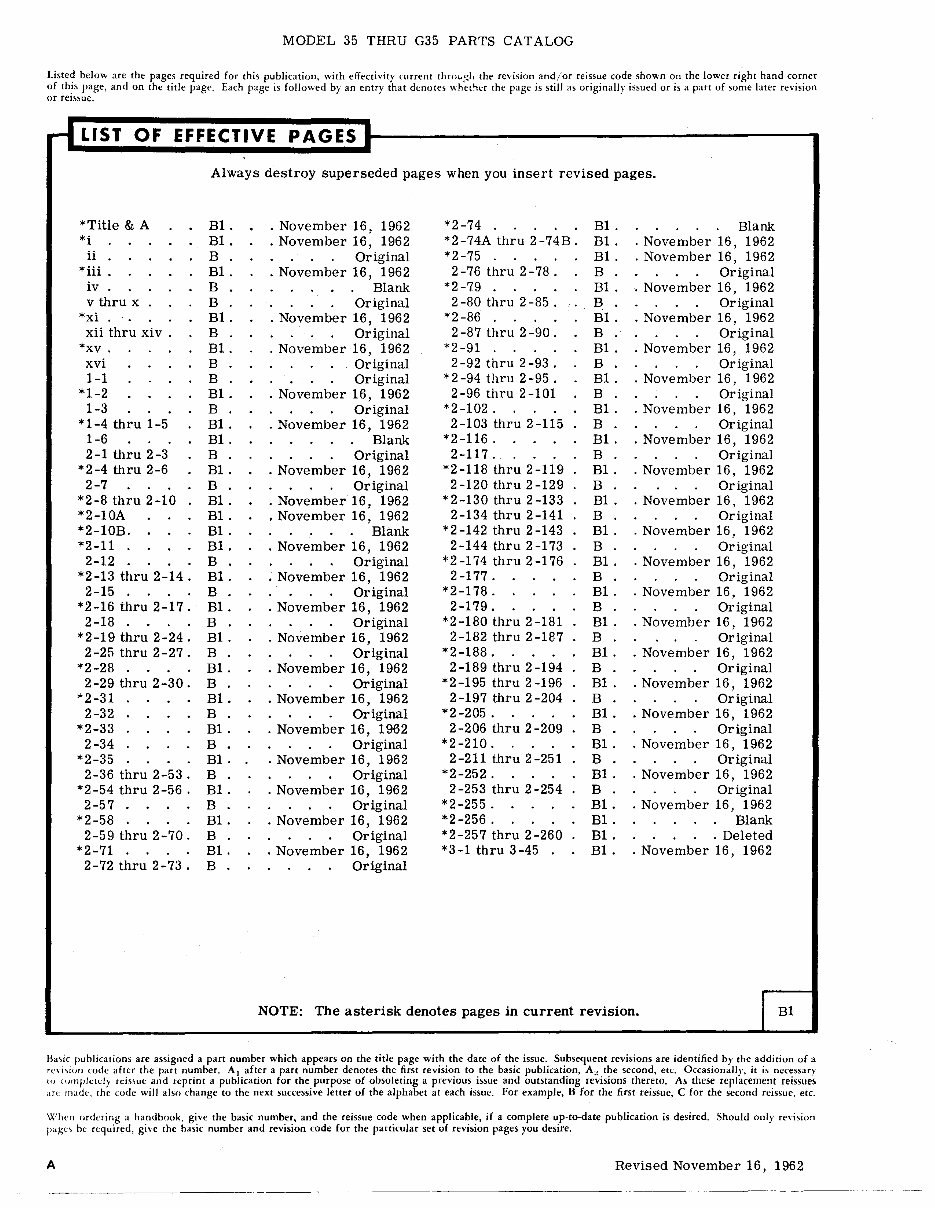
MODEL 35 THRU G35 PARTS CATALOG Listed below are the pages required for this publication, with effectivity current thro~:,I. the revision and/or reissue code shown on the lower right hand corner of thIS page, and on the title page, Each page is followed by an entry that denotes "het".r the page is still as originally issued or is a part of some later revision or relS~uc. riLiST OF EFFECTIVE PAGES: Always destroy superseded pages when you insert revised pages. *Title & A Bl. · November 16, 1962 *2-74 B1. Blank *i Bl. · November 16, 1962 *2-74A thru 2-74B. Bl. · November 16, 1962 ii B Original *2-75 B1. · November 16, 1962 * iii Bl. · November 16, 1962 2-76 thru 2-78. B Original iv B Blank *2-79 Bl. · November 16, 1962 v thru x B Original 2-80 thru 2-85. B Original *xi . Bl. · November 16, 1962 *2-86 Bl. · November 16, 1962 xii thru xi v . B Original 2-87 thru 2-90. B Original *xv. Bl. · November 16, 1962 *2-91 B1. · November 16, 1962 xvi B Original 2 -92 thru 2 -93 . B Original 1-1 B Original *2-94 thru 2-95. B1. · November 16, 1962 *1-2 Bl. · November 16, 1962 2-96 thru 2-101 B Original 1-3 B Original *2-102. B1. · November 16, 1962 *1-4 thru 1-5 Bl. · November 16, 1962 2 -103 thru 2 -115 B Original 1-6 Bl. Blank *2-116. B1. · November 16, 1962 2-1 thru 2-3 B Original 2-117. B Original *2-4 thru 2-6 Bl. · November 16, 1962 *2-118 thru 2-119 Bl. · November 16, 1962 2-7 B Original 2-120 thru 2-129 B Original *2-8 thru 2-10 Bl. · November 16, 1962 *2-130 thru 2-133 Bl. · November 16, 1962 *2-10A Bl. • November 16, 1962 2-134 thru 2-141 B Original *2-10B. Bl. Blank *2-142 thru 2-143 B1. · November 16, 1962 *2-11 Bl. · November 16, 1962 2 -144 thru 2 -173 B Original 2-12 B Original *2-174 thru 2-176 Bl. · November 16, 1962 *2-13 thru 2-14. Bl. · November 16, 1962 2-177. B Original 2-15 B Original *2-178. B1. · November 16, 1962 *2-16 thru 2-17. Bl. · November 16, 1962 2-179. B Original 2-18 B Original *2-180 thru 2-181 Bl. · November 16, 1962 *2-19 thru 2-24. Bl. · November 16, 1962 2-182 thru 2-187 B Original 2-25 thru 2-27. B Original *2-188. Bl. · November 16, 1962 *2-28 Bl. · November 16, 1962 2-189 thru 2-194 B Original 2-29 thru 2-30. B Original *2 -195 thru 2 -196 B1. · November 16, 1962 *2-31 Bl. · November 16, 1962 2-197 thru 2-204 B Original 2-32 B Original *2-205. Bl. · November 16, 1962 *2-33 Bl. · November 16, 1962 2 -206 thru 2 -209 B Original 2-34 B Original *2-210. B1. · November 16, 1962 *2-35 Bl. · November 16, 1962 2-211 thru 2-251 B Original 2-36 thru 2-53. B Original *2-252. Bl. · November 16, 1962 *2-54 thru 2-56 . Bl. · November 16, 1962 2 -253 thru 2 -254 B Original 2-57 B Original *2-255. Bl. · November 16, 1962 *2-58 Bl. · November 16, 1962 *2-256. Bl. Blank 2-59 thru 2-70. B Original * 2 -25 7 thru 2 -260 Bl. . Deleted *2-71 Bl. · November 16, 1962 *3-1 thru 3-45 B1. · November 16, 1962 2-72 thru 2-73. B Original NOTE: The asterisk denotes pages in current revision. JBl B"ic publication; are assigned a part number which appears on the title page with the date of the issue, Subsequent revisions are identified by the addition of a revi"lion (:ode after the part number. A1 after a part number denotes the first revision to the basic publication, A;.! the second, etc. Occasionally, it is necessary to lOfIll'lctely rei»ue and reprint a publication for the purpose of obsoleting a previous issue and outslanding revisions Ihereto. As Ihese replacement reissues ,Ht: made, the code will also change to the next successive letter of Ihe alphabet at each issue. For example, B for the first reissue, C for the second reissue. etc. When ordering a handbook, give the basic number, and the reissue code when applicable, if a complete up·to-date publication is desired. Should only revision pages be required, give the basic number and revision code for the particular set of revision pages you desire. A Revised November 16, 1962
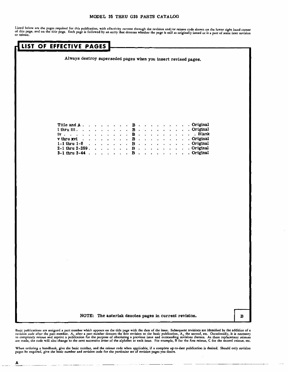
MODEL 35 THRU G35 PARTS CATALOG Liste~ below are tbe page.s required for this p~blication, with effectivity current through the revision and/or reissue code shown on the lower right hand corner of th!s page, and on the tItle page. Each page IS followed by an entry that denotes whether the page is still as originally issued or is a part of some later revision or reissue. rI LIST OF EFFECTIVE PAGES l Always destroy superseded pages when you insert revised pages. Title and A B Original i thru iii. B Original iv . B . Blank vthruxvt B Original 1-1 thru 1-6 B Original 2-1 thru 2-259 . B Original 3-1 thru 3-44 B Original NOTE: The asterisk denotes pages in current revision. Basic publications are assigned a part number which appears on the title page with the date of the issue. Subsequent revisions are identified by the addition of a revision code after the part number. Al after a part number denotes the first revision to the basic publication, A~ the second, etc. Occasionally, it is necessary to completely reissue and reprint a publication for the purpose of obsoleting a previous issue and outstanding revisions thereto. As these replacement reissues are made, the code will also change to tbe next successive letter of the alphabet at each issue. For example, B for tbe first reissue, C for tbe second reissue, etc. When ordering a handbook, give the basic number, and the reissue code when apl'licable, if a complete up·to-date publication is desired. Should only revision pages be required, give the basic number and revision code for the particular set of revision pages you desire. A
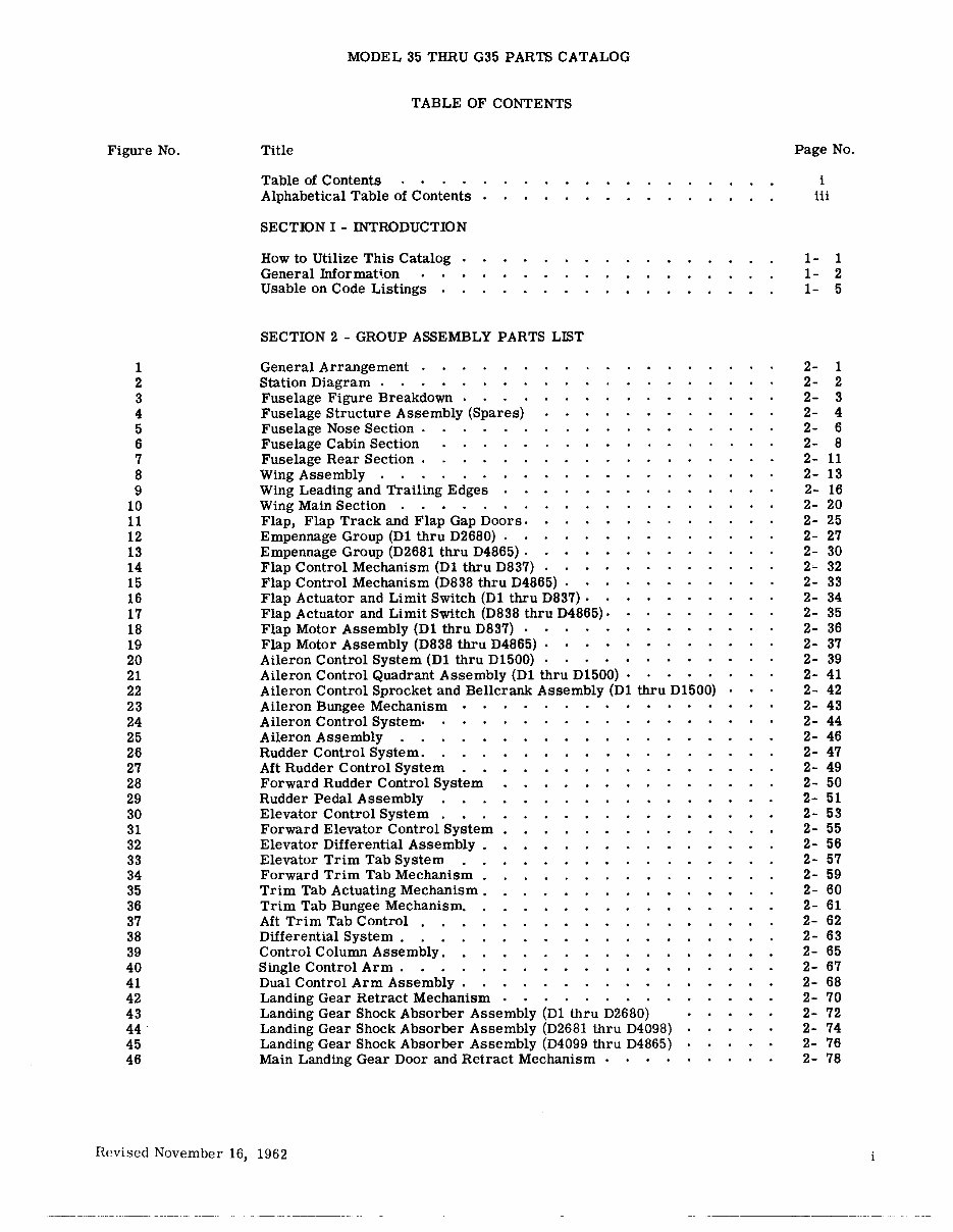
Figure No. 1 2 3 4 5 6 7 8 9 10 11 12 13 14 15 16 17 18 19 20 21 22 23 24 25 26 27 28 29 30 31 32 33 34 35 36 37 38 39 40 41 42 43 44 45 46 MODEL 35 THRU G35 PARTS CATALOG TABLE OF CONTENTS Title Table of Contents Alphabetical Table of Contents SECTION I - INTRODUCTION How to Utilize This Catalog GenerallnformaHon Usable on Code Listings . SECTION 2 - GROUP ASSEMBLY PARTS LIST General Arrangement . Station Diagram . Fuselage Figure Breakdown Fuselage Structure Assembly (Spares) Fuselage Nose Section . Fuselage Cabin Section Fuselage Rear Section . Wing Assembly . Wing Leading and Trailing Edges Wing Main Section . Flap, Flap Track and Flap Gap Doors. Empennage Group (D1 thru D2680) . Empennage Group (D2681 thru D4865) . Flap Control Mechanism (D1 thru D837) Flap Control Mechanism (D838 thru D4865) Flap Actuator and Limit Switch (Dl thru D837) . Flap Actuator and Limit Switch (D838 thru D4865) . Flap Motor Assembly (D1 thru D837) . Flap Motor Assembly (D838 thru D4865) . Aileron Control System (D1 thru D1500) . Aileron Control Quadrant Assembly (D1 thru D1500) . Aileron Control Sprocket and Bellcrank Assembly (D1 thru D1500) Aileron Bungee Mechanism Aileron Control System· Aileron Assembly Rudder Control System. Aft Rudder Control System Forward Rudder Control System Rudder Pedal Assembly Elevator Control System . Forward Elevator Control System Elevator Differential Assembly . Elevator Trim Tab System Forward Trim Tab Mechanism . Trim Tab Actuating Mechanism. Trim Tab Bungee Mechanism. Aft Trim Tab Control . Differential System . Control Column Assembly. Single Control Arm . Dual Control Arm Assembly • Landing Gear Retract Mechanism Landing Gear Shock Absorber Assembly (D1 thru D2680) Landing Gear Shock Absorber Assembly (D2681 thru D4098) Landing Gear Shock Absorber Assembly (D4099 thru D4865) Main Landing Gear Door and Retract Mechanism . Revised November 16, 1962 Page No. i iii 1- 1 1- 2 1- 5 2- 1 2- 2 2- 3 2- 4 2- 6 2- 8 2- 11 2- 13 2- 16 2- 20 2- 25 2- 27 2- 30 2- 32 2- 33 2- 34 2- 35 2- 36 2- 37 2- 39 2- 41 2- 42 2- 43 2- 44 2- 46 2- 47 2- 49 2- 50 2- 51 2- 53 2- 55 2- 56 2- 57 2- 59 2- 60 2- 61 2- 62 2- 63 2- 65 2- 67 2- 68 2- 70 2- 72 2- 74 2- 76 2- 78
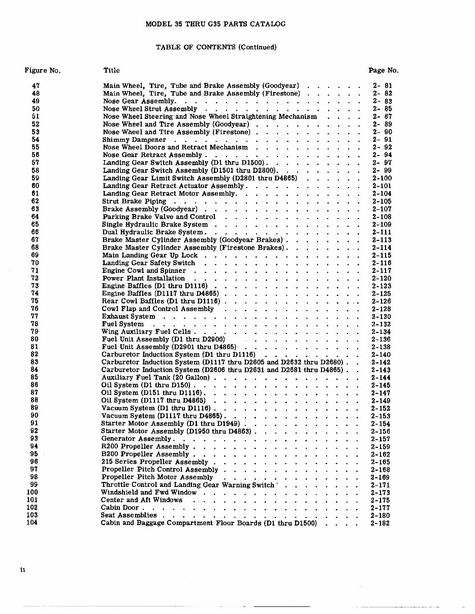
Figure No. il 47 48 49 50 51 52 53 54 55 56 57 58 59 60 61 62 63 64 65 66 67 68 69 70 71 72 73 74 75 76 77 78 79 80 81 82 83 84 85 86 87 88 89 90 91 92 93 94 95 96 97 98 99 100 101 102 103 104 MODEL 35 THRU G35 PARTS CATALOG TABLE OF CONTENTS (Continued) Title Main Wheel, Tire, Tube and Brake Assembly (Goodyear) Main Wheel, Tire, Tube and Brake Assembly (Firestone) Nose Gear Assembly. . . . . Nose Wheel Strut Assembly . . Nose Wheel Steering and Nose Wheel Straightening Mechanism Nose Wheel and Tire Assembly (Goodyear) Nose Wheel and Tire Assembly (Firestone) Shimmy Dampener . Nose Wheel Doors and Retract Mechanism Nose Gear Retract Assembly.. .•• Landing Gear Switch Assembly (Dl thru D1500). . Landing Gear Switch Assembly (D1501 thru D2800). Landing Gear Limit Switch Assembly (D2801 thru D4865) Landing Gear Retract Actuator Assembly. Landing Gear Retract Motor Assembly. Strut Brake Piping . Brake Assembly (Goodyear) . . Parking Brake Valve and Control Single Hydraulic Brake System . Dual Hydraulic Brake System. ..... • Brake Master Cylinder Assembly (Goodyear Brakes) . Brake Master Cylinder Assembly (Firestone Brakes) . Main Landing Gear Up Lock Landing Gear Safety Switch Engine Cowl and Spinner . Power Plant Installation . . Engine Baffles (Dlthru Dlll6) • Engine Baffles (Dll17 thru D4865) Rear Cowl Baffles (Dl thru Dll16) Cowl Flap and Control Assembly Exhaust System . . Fuel System Wing Auxiliary Fuel Cells. . . . Fuel Unit Assembly (Dl thru D2900) Fuel Unit Assembly (D2901 thru D4865) . . Carburetor Induction System (Dl thru Dlll6) .. . . .. Carburetor Induction System (Dlll7 thru D2605 and D2632 thru D2680) . Carburetor Induction System (D2606 thru D2631 and D2681 thru D4865) . Auxiliary Fuel Tank (20 Gallon) Oil System (Dl thru D150) . . Oil System (D151 thru Dll16). . . Oil System (D1117 thru D4865) Vacuum System (Dl thru D1116). . Vacuum System (D1117 thru D4865). • Starter Motor Assembly (Dl thru D1949). • Starter Motor Assembly (D1950 thru D4863) . Generator Assembly. R200 Propeller Assembly. . B200 Propeller Assembly. . 215 Series Propeller Assembly . Propeller Pitch Control Assembly Propeller Pitch Motor Assembly . . Throttle Control and Landing Gear Warning Switch' Windshield and Fwd Window Center and Aft Windows Cabin Door. Seat Assemblies . . • .. ..... . Cabin and Baggage Compartment Floor Boards (D1 thru D1500) ------- ------ ----------------------- ------ Page No. 2- 81 2- 82 2- 83 2- 85 2- 87 2- 89 2- 90 2- 91 2- 92 2- 94 2- 97 2- 99 2-100 2-101 2-104 2-105 2-107 2-108 2-109 2-111 2-113 2-114 2-115 2-116 2-117 2-120 2-123 2-125 2-126 2-128 2-130 2-132 2-134 2-136 2-138 2-140 2-142 2-143 2-144 2-145 2-147 2-149 2-152 2-153 2-154 2-156 2-157 2-159 2-162 2-165 2-168 2-169 2-171 2-173 2-175 2-177 2-180 2-182
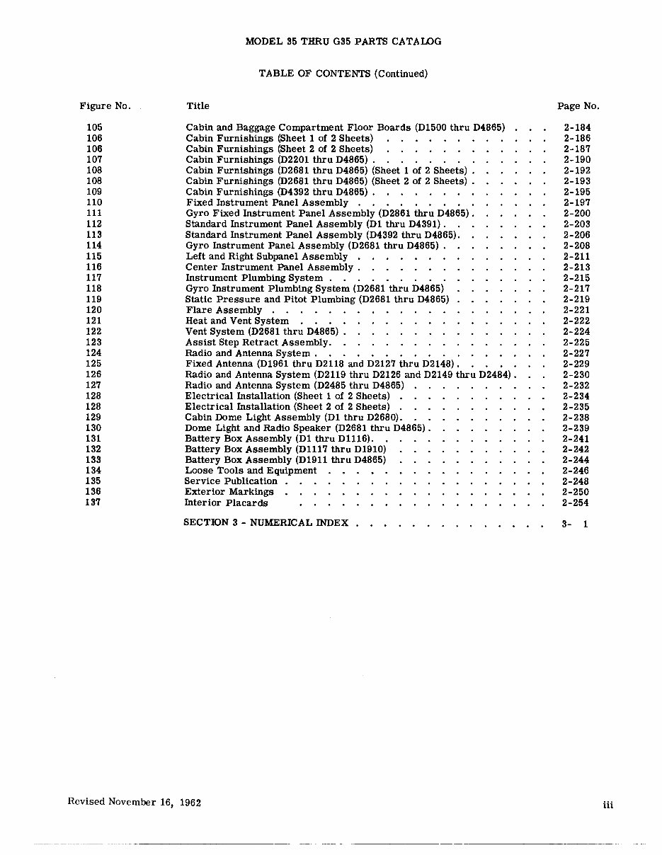
Figure No. 105 106 106 107 108 108 109 110 111 112 113 114 115 116 117 118 119 120 121 122 123 124 125 126 127 128 128 129 130 131 132 133 134 135 136 137 MODEL 35 THRU G35 PARTS CATALOG TABLE OF CONTENTS (Continued) Title Cabin and Baggage Compartment Floor Boards (D1500 thru D4865) Cabin Furnishings (Sheet 1 of 2 Sheets) Cabin Furnishings (Sheet 2 of 2 Sheets) Cabin Furnishings (D2201 thru D4865) . . Cabin Furnishings (D2681 thru D4865) (Sheet 1 of 2 Sheets) . Cabin Furnishings (D2681 thru D4865) (Sheet 2 of 2 Sheets) . Cabin Furnishings (D4392 thru D4865) . Fixed Instrument Panel Assembly . Gyro Fixed Instrument Panel Assembly (D2861 thru D4865). Standard Instrument Panel Assembly (D1 thru D4391) . Standard Instrument Panel Assembly (D4392 thru D4865). Gyro Instrument Panel Assembly (D2681 thru D4865) . Left and Right Subpanel Assembly . Center Instrument Panel Assembly . Instrument Plumbing System.. ..... . Gyro Instrument Plumbing System (D2681 thru D4865) Static Pressure and Pitot Plumbing (D2681 thru D4865) Flare Assembly . . Heat and Vent System . Vent System (D2681 thru D4865) . Assist Step Retract Assembly. Radio and Antenna System. . . . . . . . . . . Fixed Antenna (D1961 thru D2118 and D2127 thru D2148) . Radio and Antenna System (D2119 thru D2126 and D2149 thru D2484) . Radio and Antenna System (D2485 thru D4865) Electrical Installation (Sheet 1 of 2 Sheets) . Electrical Installation (Sheet 2 of 2 Sheets) . Cabin Dome Light Assembly (D1 thru D2680). Dome Light and Radio Speaker (D2681 thru D4865) . Battery Box Assembly (D1 thru Dl116). Battery Box Assembly (D1117 thru D1910) Battery Box Assembly (D1911 thru D4865) Loose Tools and Equipment Service Publication Exterior Markings . Interior Placards SECTION 3 - NUMERICAL INDEX Revised November 16, 1962 Page No. 2-184 2-186 2-187 2-190 2-192 2-193 2-195 2-197 2-200 2-203 2-206 2-208 2-211 2-213 2-215 2-217 2-219 2-221 2-222 2-224 2-225 2-227 2-229 2-230 2-232 2-234 2-235 2-238 2-239 2-241 2-242 2-244 2-246 2-248 2-250 2-254 3- 1 iii
----- -------- ----
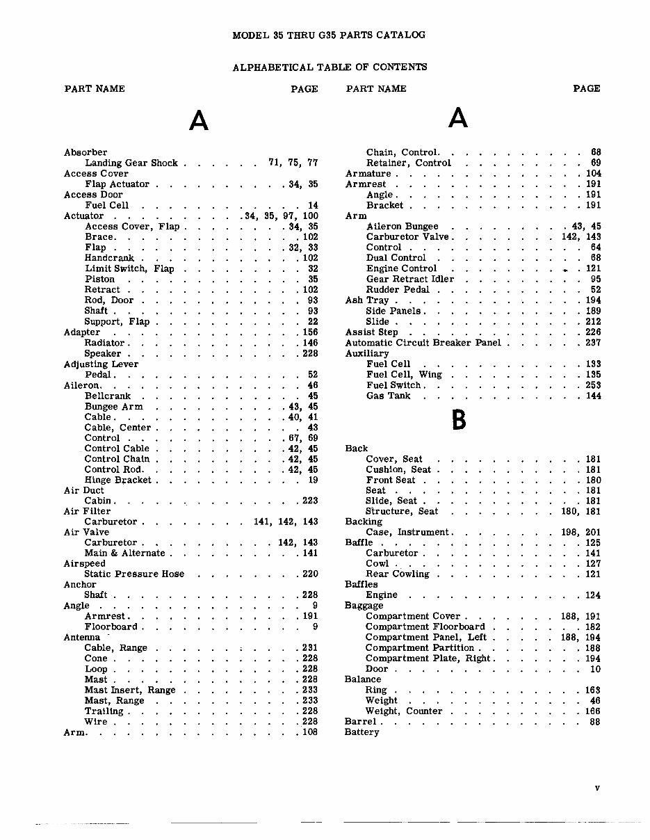
PART NAME Absorber Landing Gear Shock Access Cover Flap Actuator Access Door Fuel Cell Actuator . Access Cover, Flap. Brace. Flap. Handcrank Limit SWitch, Flap Piston Retract . Rod, Door Shaft. Support, Flap Adapter Radiator. Speaker . Adjusting Lever Pedal. Aileron. Bellcrank Bungee Arm Cable. Cable, Center. Control . Control Cable Control Chain Control Rod. Hinge B+acket . Air Duct Cabin. Air Filter Carburetor. Air Valve Carburetor . Main & Alternate . Airspeed Static Pressure Hose Anchor Shaft. Angle . Armrest. Floorboard . Antenna - Cable, Range Cone Loop. Mast. Mast Insert, Range Mast, Range Trailing. Wire Arm. A MODEL 35 THRU G35 PARTS CATALOG ALPHABETICAL TABLE OF CONTENTS PAGE 71, 75, 77 · 34, 35 · 14 .34, 35, 97, 100 · 34, 35 · 102 · 32, 33 · 102 · 32 · 35 · 102 93 · 93 · 22 · 156 · 146 .228 52 46 45 .43, 45 .40, 41 43 · 67, 69 .42, 45 .42, 45 .42, 45 · 19 .223 141, 142, 143 142, 143 · 141 .220 .228 9 · 191 9 .231 .228 .228 .228 .233 .233 .228 .228 · 108 PART NAME A Chain, Control. Retainer, Control Armature. Armrest . Angle. Bracket Arm Aileron Bungee Carburetor Valve. Control . Dual Control Engine Control Gear Retract Idler Rudder Pedal Ash Tray. Side Panels. Slide. Assist Step Automatic Circuit Breaker Panel Auxiliary Fuel Cell Fuel Cell, Wing Fuel Switch. Gas Tank Back Cover, Seat Cushion, Seat Front Seat Seat . Slide, Seat Structure, Seat Backing B Case, Instrument. Baffle . Carburetor. Cowl. Rear Cowling Baffles Engine Baggage Compartment Cover . Compartment Floorboard Compartment Panel, Left Compartment Partition . Compartment Plate, Right. Door Balance Ring Weight Weight, Counter Barrel. Battery PAGE 68 69 104 191 191 191 43, 45 142, 143 64 68 121 95 52 194 180, 198, 188, 188, 189 212 226 237 133 135 253 144 181 181 180 181 181 181 201 125 141 127 121 124 191 182 194 188 194 10 163 46 166 88 v
PART NAME Battery (Continued) Box Beacon Clip, Marker Bearing Pinion Shaft. Pitch Control Belt Harness, Seat Safety. Seat Safety . Blade Blade & Weight Propeller Block Support Body Dome Light. Filler Valve Window Bolt Lower Drag Leg Boot. Rudder Pedal Switch Bottom Cushion, Seat Panel, Cabin Panel, Tail. Seat Box Battery Glove Compartment Map Compartment Brace Actuator. Cover. Main Gear Nose Gear Nose Wheel. Bracket Aileron Hinge Armrest. Cowl Fastener. Flap Track. Motor Support . Pulley. Pulley Support. Speaker . Suction Relief Valve. Three Unit . Brake Clamp, Strut Control, Parking. Fluid Reservoir Goodyear. vi B MODEL 35 THRU G35 PARTS CATALOG ALPHABETICAL TABLE OF CONTENTS (Continued) PAGE 241, 243, 245 .231 · 161 · 160 PART NAME Handle, Parking Master Cylinder Tube . Valve, Parking Wire, Parking. Braze Cylinder. Breaker PAGE B 108 .112, 113, 114 110 108 108 113, 114 · 181 Compartment Door, Map & Circuit . Panel, Automatic Circuit 212 237 · 181 163, 166 · 163 · 161 .226 .238 73, 75, 77 . 174 95 . 115 183, 185, 188 .116 · 180 5 5 180, 181 241, 243, 245 198, 201 .212 · 102 .144 71 · .95 86 Panel, Circuit. Breather Tube, Crankcase. Brush . Holder Plate. Spring Bulkhead Lower Firewall Lower Station 179 . Lower Station 207 Lower Station 233.5 . Station 151 . Station 151 Mating Station 246. 3 Station 256.9 Station 272 . Bungee Arm, Aileron Cable. Bushing Clutch Cabin c 201 150 37,156,163,170 37 158 104 7 11 11 11 11 5 11 5, 11 5, 11 43, 45 61 155 . 153, 163, 189, 210, 231 Air Duct. Bottom Panel Dome Light. Door. 223 5 194, 238 178 19 · 191 .118 18 · 166 49 62 .228 .218 .221 82 · 106 .110 .112 81 Door Gimp . Door Handle . Door Handle Inside Shaft Door Outside Handle Support Rug . Cable . Aileron . Aileron Control Bungee . . Center Aileron Drum, Tab Elevator Control Lower. Phone & Speaker Range Antenna 188, 194 191 178 178 185 228, 229 40, 41 42, 45 42, 61 43 . 59 .54, 55, 56 40 228 . 231
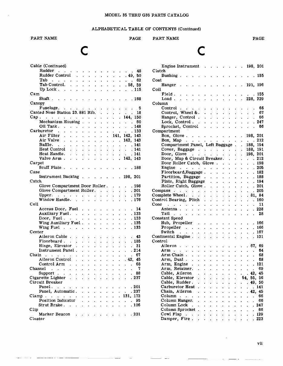
MODEL 35 THRU G35 PARTS CATALOG ALPHABETICAL TABLE OF CONTENTS (Continued) PART NAME Cable (Continued) Rudder . Rudder Control Tab Tab Control. Up Lock. Cam Shaft. Canopy Fuselage. c Canted Nose Station 23.881 Rib. Cap. Mechanism Housing Oil Tank. Carburetor Air Filter Air Valve Baffle. Heat Control Heat Handle. Valve Arm Carpet Scuff Plate Case Instrument Backing Catch Cell Glove Compartment Door Roller. Glove Compartment Roller. Upper. Window Handle. Access Door, Fuel Auxiliary Fuel. Door, Fuel. Wing Auxiliary Fuel. Wing Fuel . Center Aileron Cable Floorboard. Hinge, Elevator Instrument Panel . Chain . Aileron Control Control Arm Channel Support . Cigarette Lighter Circuit Breaker Panel. Panel, Automatic. Clamp. Clip Position Indicator Strut Brake. Marker Beacon Cluster PAGE 48 .49, 50 62 .58, 59 .115 · 168 5 18 144, 150 · 60 · 148 · 133 141, 142, 143 142, 143 · 141 · 141 · 141 142, 143 · 188 198, 201 · 198 . 201 · 179 · 176 · 14 · 133 · 133 · 135 · 133 · 43 · 185 · 31 .214 67 .42, 45 68 7 88 .237 .201 .237 131, 172 · 95 · 106 .231 PART NAME c Engine Instrument Clutch Bushing Coat Hanger Coil Field. Load. Column Control Control, Wheel &. Hanger, Control . Lock, Control. Sprocket, Control Compartment Box, Glove. BOX, Map Compartment Panel, Left Baggage Cover, Baggage . Door, Glove Door, Map & Circuit Breaker. Door Roller Catch, Glove Engine Floorboard,Baggage . Partition, Baggage . Plate, Right Baggage Roller Catch, Glove . Compass . Complete Wheel. Control Bearing, Pitch Cone Antenna. Tail . Constant Speed Hub, Propeller Propeller Switch Continental Engine. Control Aileron . Arm. Arm Chain Arm, Dual Arm, Engine Arm, Retainer. Cable, Aileron Cable, Elevator Cable, Rudder. Carburetor Heat Chain, Aileron Column . Column Hanger. Column Lock . Column Sprocket Cowl Flap . Damper, Fire . PAGE 198, 201 155 191, 196 155 228, 229 66 67 66 247 66 198, 201 212 188, 194 188, 191 198, 201 212 198 205 182 188 194 201 205 81, 84 160 11 228 28 166 166 167 121 67, 69 64 68 68 121 69 42, 45 54, 55, 56 49, 50 . 141 42, 45 66 66 247 66 129 223 vii
This complete factory illustrated parts catalog for the Beechcraft Bonanza Model 35 & G35 is an invaluable resource for both professional mechanics and DIY enthusiasts. It is instantly accessible and compatible with all versions of Windows and Mac. The manual is written in English and is designed to be easily searchable, bookmarked, and indexed for quick reference.
Featuring easy-to-read files, this manual can be viewed, zoomed, and printed on any computer. It serves as an excellent reference source for home, repair shop, or business use. Please note that it is non-current and sold for informational purposes only.
For immediate access to this manual, simply click the green and white button located at the top right-hand side of this page. Additionally, we offer a wide range of airplane and engine manuals, so feel free to email us about any other manuals you may need.
Recently Viewed
5,521,897Happy Clients
2,594,462eManuals
1,120,453Trusted Sellers
15Years in Business
Price:
Actual Price:
Beechcraft Bonanza 35 thru G35 IPC Parts Catalog Manual -