PUBLI~SHED BY COMMERCIAL PUBLICATIONS BEECH AIRCRAFT CORPORATION WICHITh, ICA.USXS 67201 U. S. IZ. ~eechcraft ~ M´•mb´•r of C*MA ~~ Gmral*rioPn n ~v~wa~ Company ~I M.nvtormr´•n ~uodbia,
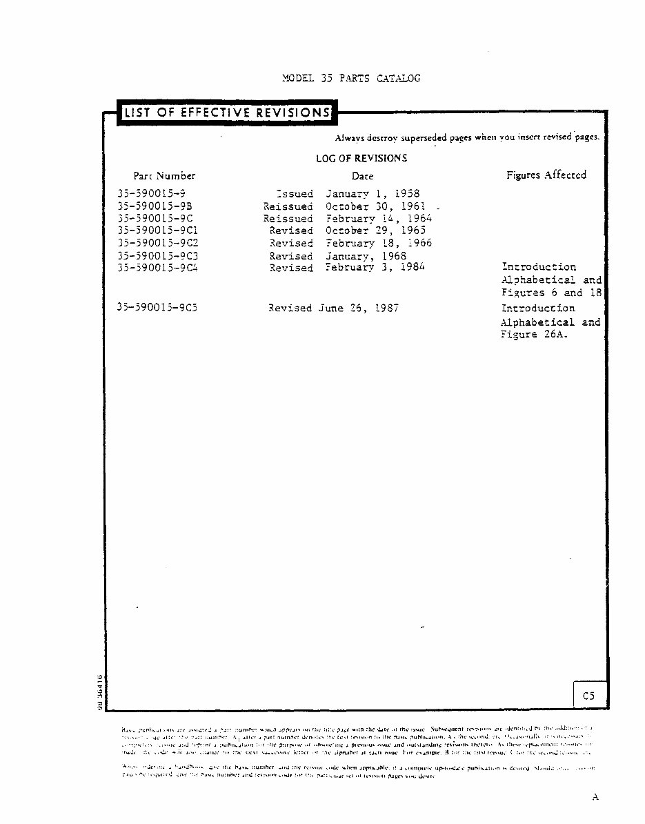
~IODEZ. 3~ P~RTS Z~l~i~OG LIST OF EFFECTIVE REVISIONS Alwavs dcsrtov superseded paees whcrl vou insert revised pages. LOC OF REVlSIONS Parr Number Dare Figures Affected 35-5900!~-9 Issued january i, 1998 35-~90015-9B Reissued October 30, 19B1 35-590015-9C Reissued february Ih, 1964 3j-590015-9Cl Revised October 29, 196S 35-590015-9C2 Revised Zebr~ary 18, 1966 3~-59001~-aC3 Revised janua~y, 1968 35-590015-9~~ Revised february 3, i986 Introduc",ion Xi~hzbetical and Figares 6 and 18 3j-~90015-9CS Revised june 25, 198T Zntroduction Alphabetical and "igur~ 26A. 31 1 C5 ´•;´•; .´•~´•´•´• j;´•.l:;´•´•:!r :´•;:: :;u:llr:: ´•\ I .Il~r. pit: :n~~ll~E: ~rll.´•:~´• :~le ~;:~I r\lIl.´•r: :.´• i((~ ~JIIC ~Vh(lc~(ll’)l. ~.:hC~~i"tlJ. i´•l~ I )~-´•l~ll´•llii!\ I: :\ O~.....I "::.:: ~Jcr~l:i ; I:I~IJLI...´•~ J~C ItlC k.~ll ::U::IDC1 ~1I~:!IC (i´•I\\IIC .1IJC i~ilCn J~P)Li´•lhlC L! ´•1 ~()IIIIIICIC Ilpr(´•~´•l!~´• F~lnil~~LII´•II II CCIIII´•J \jil´•llii ´•´•´•´•´•´•
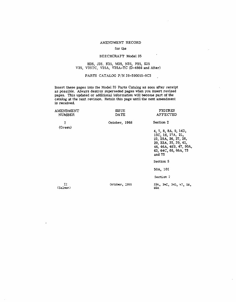
XMENDMENT RECORD for the BEECHCRAFT Mode135 H35, 535, fC35, M35, N35, P35, S35 V35, V35TC, V35A: ~35A-TC (0-4866 and After) PARTS CATALOG P/N 35-590015-9C3 Insert these pages into the Model 35 Parts Catalog as soon after receipt as possible. Always destroy superseded pages when you insert revised pages. This updated or additional information will become part of the catalog at the next revision. Retain this page until the next amendment is received AMENDMENT ISSUE FIGURES NUMBER DATE AFFECTED I October, 1968 Section 2 (Green) 4, 7, 8, 8A, 9, 14D, 15C, 16, 17A, 21, 23, 25A, 26, 27, 28, 29, 33A, 35, 39, 41, 46, 46A, 46B, 47, 50A, 63, 64C, 66, 66A, 73 and 75 Section 5 50A, 101 Section 2 October, 1969 33A, 34C, 3~D, ~t7, 58, (Sa5~n) 66A
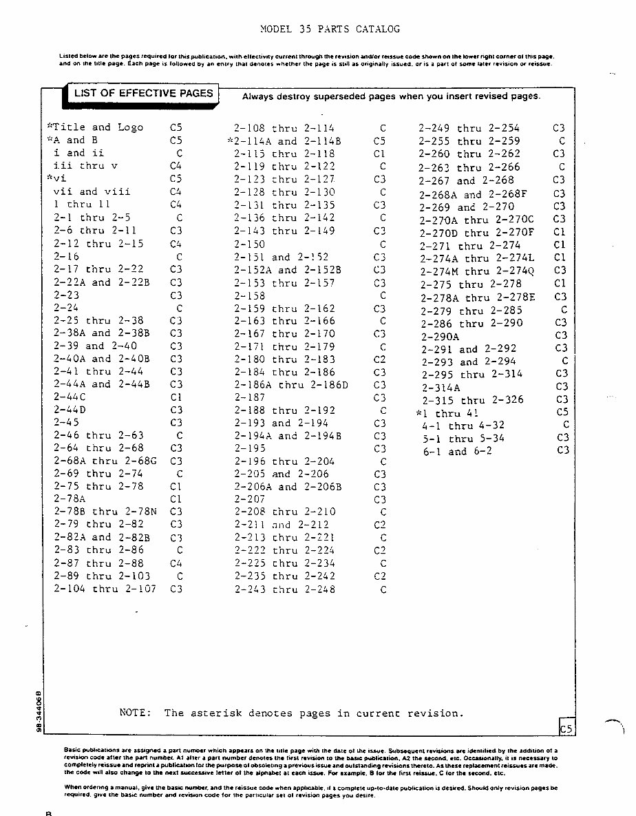
~ODEL 35 PXRTS CATXLOG Listed below are the pages required lor this public~tion. with elfeclivity currentthrougn the revision ~ndlor ~~s+ut code shown on the lower nght corner of this page. and on the title page. Each page in followed by In entry that denotes whether the page is sull as origin.lly issued. or is a part of some later revision or reissue. LIST OF EFFECTIVE PAGES i Always destroy superseded pages when you insert revised pages. "Title and Logo C5 2-108 thru 2-114 C 2-249 thru 2-254 C3 "A and B C5 "2-11~~ and 2-114B C5 2-255 thru 2-259 C i and ii C 2-115 thru 2-118 C1 2-260 thru 2-262 C3 iii thru V C4 2-119 thru 2-122 C 2-26? thru 2-266 C "vi C5 2-123 thru 2-127 C3 2-267 and 2-268 03 vii and viii C4 2-128 thru 2-130 C 2-2686 and 2-268F C3 1 thru 11 C4 2-131 thru 2-135 C3 2-269 and 2-270 03 2-1 thru 2-5 C 2-136 thru 2-142 C 2-270A thru 2-270C C3 2-6 thru 2-11 C3 2-143 thru 2-149 C3 2-270D thru 2-270F C1 2-12 thru 2-15 C4 2-150 C 2-271 thru 2-274 C1 2-16 0 2-151 and 2-!j2 C3 2-274A thru 2-274t C1 2-17 thru 2-22 C3 2-152X and 2-152B C3 2-274M thru 2-274~ 03 2-22A and 2-22B C3 2-153 thru 2-15? C3 2-275 thru 2-278 C1 2-23 C3 2-158 C 2-278A thru 2-278E C3 2-24 C 2-159 thru 2-162 C3 2-279 thru 2-285 C 2-25 thru 2-38 C3 2-163 thru 2-166 C 2-286 thru 2-290 C3 2-38A and 2-38B (73 2-167 thru 2-170 C3 2-290A 03 2-39 and 2-40 C3 2-171 thru 2’179 C. 2-291 and 2-292 C3 2-40A and 2-40B C3 2-180 thru 2-183 C2 2-293 and 2-294 C 2-41 thru 2-44 C3 2-184 thru 2-186 C3 2-295 thru 2-314 03 2-441\ and 2-44B C3 2-186A thru 2-186D C3 2-3146 C3 2-44C C1 2-187 Cj 2-315 thru 2-326 03 2-44D C3 2-188 thru 2-192 C kl thru 41 C5 1-45 03 2-193 and 2-194 C3 4-1 thru 4-32 C 2-46 thru 2-63 C 2-194X and 2-194B C3 5-1 thru 5-34 C3 2-64 thru 2-68 C3 2-195 c3 6-1 and 6-2 03 2-68A thru 2-68G 03 2-196 thru 2-204 C 2-69 thru 2-74 C 2-205 and 2-306 03 2-75 thru 2-78 C1 2-206a and 2-206B C3 2-78A C1 2-207 C3 2-78B thru 2-78N C3 2-208 thru 2-210 C 2-79 thru 2-82 C3 2-211 nnd 2-212 C2 2-82A and 2-82B C3 2-213 thru 2-221 C 2-83 thru 2-86 C 2-222 thru 2-224 C2 2-87 thru 2-88 C4 2-225 thru 2-234 C 2-89 thru 2-103 C 2-235 thru 2-242 C2 2-104 thru 2-107 03 2-243 thru 2-258 C NOTE: The asterisk denotes pages in current revision. basic publications are assigned a part number which appears on the title page with the date ct the issue. subsequent revtsions are idcnlifKd by the addition of 1 revi~lon code after the part number a1 after a part number denoces the first revision to the bauc publication. A2 the second. etc. Occasionally. it is necessary to completely rerssue and reprint 1 publication for the purpose of o~solel~ng a previous issue and outstanding revisions thereto. *~ these replacement reissues are made. the code will also change to Vie nut successive letter of the ~ph~bet at each issue. For c´•~mple. B for the first reissue. C for the second. etc. When ordering a manual. give the b~ss number. and the reissue code when ~ppllulle. if I Complete up-to-date publication is desired. should only revision pages be required. give the basic number and reviwon code for the part,cular sec ol revision pages you desire.
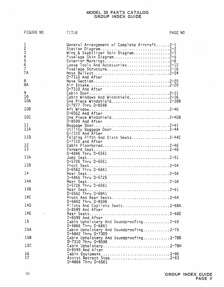
MODEL 35 PARTS CATALOG GROUP INDEX GUIDE FIGURE NO TITLE PAGE NO 1 General Arrangement of Complete Aircraft......2-l 2 Station Diagram.....:...:.....................2-2 3 Wing & Stabilizer Sk~n D~agram.......~........2-3 4 Fuselage Skin Diagram............... ..........2-5 5 Exterior Markinas....... ............ ..........2-8 6 Loose Tools And~Accessories..... ..............2-12 7 Fuselage Structure.............. .........,,.2-16 7A Nose Bal~ast.........................,........2-24 0-7310 And After 8 Nose Section..................................2-25 8A Air Intake.......... ................ ..........2-29 0-7310 And After 9 Cabin Door......... .....................2-31 10 Cabin Windows And W;ndshield..................2-36 10A One Piece Windrhield..........................2-388 0-7977 Thru 0-8598 10B Aft Window..................... ............,..2-40 0-6562 And After 10C One Piece Windshield..........................2-40B 0-8599 And After 11 Baggage Door..................................2-41 11A Utility Baggage Door..........................2-44 0-7310 And After 11B Folding Fifth And Sixth Seats.................2-44C 0-7310 and After 12 Cabin Floorborad..............................2-46 13 Forward Seat..................................2-48 0-4866 Thru 0-6561 13A Jump Seat.....................................2-51 0-5726 Thru 0-6561 135 Front Seat....................................2-54 0-6562 Thru 0-6841 14 Rear Seat.......... ........................ ...2-56 3-4866 Thru 0-5725 14A Rear Seat.... ................., ..............2-58 0-5726 Thru 0-6561 148 Rear Seat.... ................... .........,,.2-61 0-6562 Thru 0-6841 14C Front And Rear Seats..........................2-64 0-6842 Thru 0-8598 140 Pilots And Copilots Seats.....................2-68A 0-8599 And After 14E Rear Seats.. .........,,,, ......... .........2-68E 0-8599 And After 15 Cabih Upholstery And Soundproofing............2-69 0-4866 Thru 0-6841 15A Cabin Upholstery And Soundproofing............2-75 0-6842 Thru 0-7309 158 Cabin Upholstery And Soundpro~fing.,......;...2-78B 0-7310 Thru 0-8598 15C Cabin UFholstery..............................2-78H 0-8599 And After 16 Cabin Equipment...............................2-80 17 Assist Retract Step...........................2-83 0-4866 Thru 0-6561 C4 ’GROUP INDEX GUIDE PAGE V
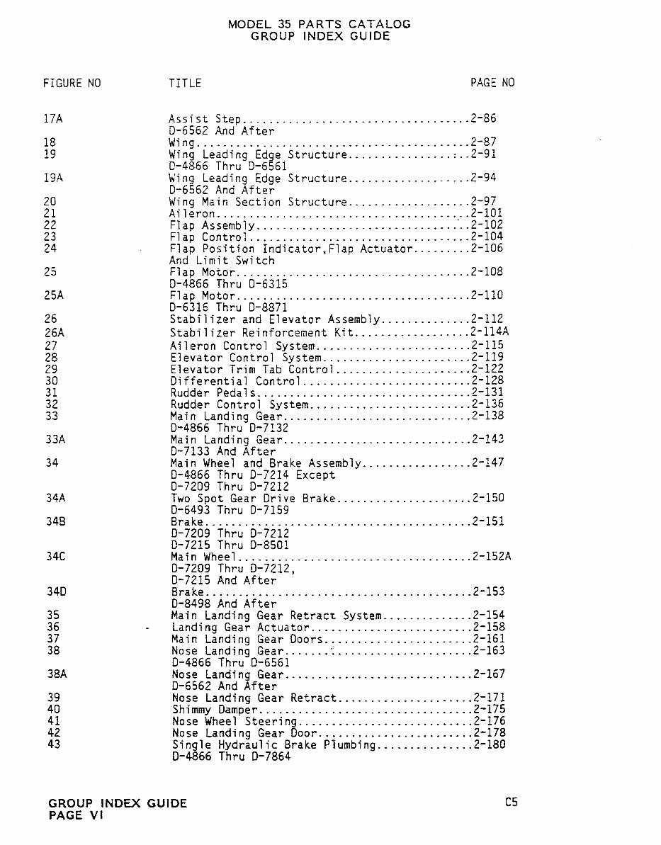
MODEL 35 PARTS CATALOG GROUP INDEX GUIDE FIGURE NO TITLE PAGE NO 17A Assist Step......... ..........................2-86 0-6562 And After 18 Wing..........................................2-87 19 Wing Leading Edge Structure................r..2-91 0-4866 Thru 0-6561 19A Wing Leading Edge Structure...................2-94 0-6562 And After 20 Wing Main Section Structure...................2-97 21 Aileron.......................................2-101 22 Flap As sembly ................... .............. 2-102 23 Flap Control..................................2-104 24 Flap Position Indicator,F~ap Actuator........,2-l06 And Limit Switch 25 Flap Motor....................................2-108 0-4866 Thru 0-6315 25A Flap Motor....................................2-110 0-6316 Thru 0-8871 26 Stabilizer and Elevator Assembly..............2-112 26A Stabilizer Reinforcement Kit..................2-114A 27 Aiferon Control System........................2-115 28 Elevator Control System.......................2-119 29 Elevator Trim Tab Control.....................2-122 30 Differential Control..........................2-128 31 Rudder Peda7s.................................2-131 32 Rudder Control System.........................2-136 33 Main Landing Gear.............................2-138 0-4866 Thru 0-7132 33A Main Landing Gear.............................2-143 0-7133 And After 34 Main Wheel and Brake Assembly.................2-147 0-4866 Thru 0-7214 Except 0-7209 Thru 0-7212 34A Two Spot Gear Drive Brake.....................2-150 0-6493 Thru 0-7159 348 Brake............................,............2-151 0-7209 Thru 0-7212 0-7215 Thru 0-8501 340 Main Wheel....................................2-152A 0-7209 Thru 0-7212, 0-7215 And After 340 Brake.........................................2-153 0-8498 And After 35 Main Landing Gear Retract System..............2-154 36 Landing Gear Actuator.........................2-158 37 Main Landing Gear Doors .....................2-161 38 Nose Landing Gear......:i. ............. ......2-163 0-4866 Thru 0-6561 38A Nose Landing Gear.............................2-167 0-6562 And After 39 Nose Landing Gear Retract.....~...............2-171 40 Shimmy Damper...,.............................2-175 41 Nose Wheel Steer~ng.....,.....................2-176 42 Nose Landing Gear Door......:.................2-178 43 Single Hydraulic Brake Plumb~ng...............2-180 0-4866 Thru 0-7864 GROUP INDEX GUIDE C5 PAGE V1
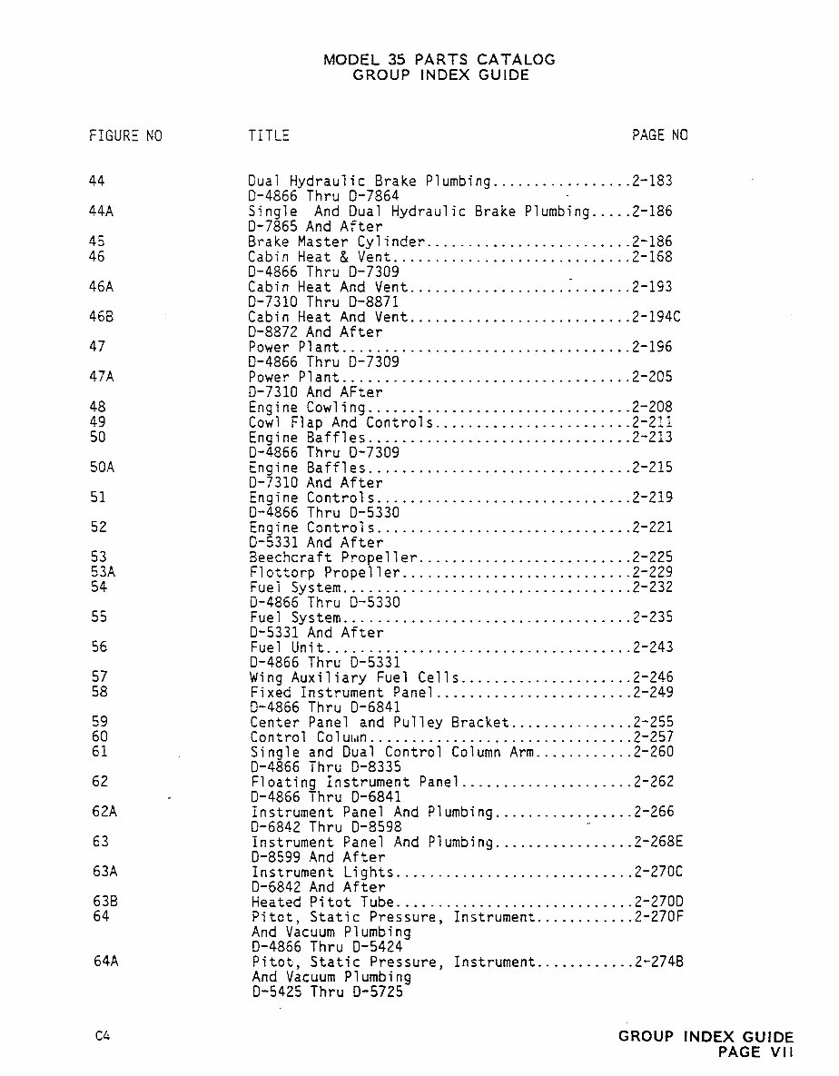
MODEL 35 PARTS CATALOG GROUP INDEX GUIDE FIGURE NO TITLE PAGE NO 44 Dual Hydraulic Brake Plumbing.................2-183 0-4866 Thru 0-7864 44A Single And Dual Hydraulic Brake Plumbing.....2-186 0-7865 And After 45 Brake Master Cylinder.........................2-186 46 Cabin Heat & Vent.............................2-158 0-4866 Thru 0-7309 46A Cabin Heat And Vent...................:.......2-193 0-7310 Thru 0-8871 46B Cabin Heat And Vent...........................2-194C 0-8872 And After 47 Power Ptant..................................,2-196 0-4866 Thru 0-7309 47A Power Plant...................................2-205 0-7310 And After 48 Engine Cowling...................... ..........2-208 49 Cowl Flap And Controls.....................,..2-211 50 Engine Baffles............................ ....2-213 0-4866 Thru 0-7309 50A Engine Baffles................................2-215 0-7310 And After 51 Engine Controls... ............................2-219 0-4866 ihru 0-5330 52 Engine Controls....... ........................2-221 0-5331 And After 53 Beechcraft Propeller..........................2-225 53A Flottorp Propeller............................2-229 54 Fuel System...................................2-232 0-4866 Thru 0-5330 55 Fuel System...................................2-235 0-5331 And After 56 Fuel Unit.....................................2-243 0-4866 rhru 0-5331 57 Wing Auxiliary Fuel Cells.....................2-246 58 Fixed Instrument Panel........................2-249 0-4866 Thru 0-6841 59 Center Panel and Pulley Gracket...............2-255 60 Control Colu~ln................................2-257 61 Single and Dual Control Column Arm............2-260 0-4866 Thru 0-8335 62 Floating Instrument Panel.....................2-262 0-4866 Thru 0-6841 62A instrument Panel And Plumbing.................2-266 0-6842 Thru 0-8598 63 Instrument Panel And Plumbing.................2-268E 0-8599 And After 63A Instrument Lights.............................2-270C 0-6842 And After 63B Heated Pitot Tube.............................2-270D 64 Pitot, Static Pressure, Instrument............2-270F And Vacuum Plumbing 0-4866 Thru 0-5424 64A Pitot, Static Pressure, Instrument............2-274B And Vacuum Plumbing 0-5425 Thru 0-5725 c4 GROUP INDEX GUIDE PAGE VII
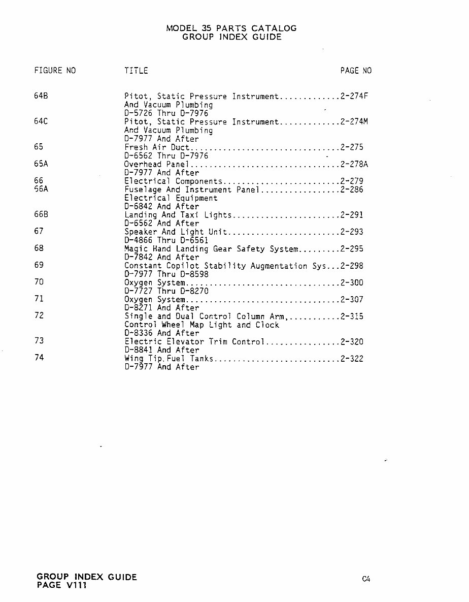
MODEL 35 PARTS CATALOG GROUP INDEX GUIDE FIGURE NO TITLE PAGE NO 648 Pitot, Static Pressure Instrument.............2-274F And Vacuum Plumbing 0-5726 Thru 0-7976 640 Pitot, Static Pressure Instrument.............2-274M And Vacuum Plumbing 0-7977 And After 65 Fresh Air Duct........ ................... .....2-275 0-6562 Thru 0-7976 65A Overhead Panel................................2-278A 0-7977 And After 66 Electrical Componentr.........................2-279 56A Fuselage And Instrument Panel..........,......2-286 Electrical Equipment 0-6842 And After 660 Landing And Taxi Lig~ts.......................2-291 0-6562 And After 67 Speaker And Light Unit. ................... ....2-293 0-4866 Thru 0-6561 68 Magic Hand Landing Gear Safety System.........2-295 0-7842 And After 69 Constant Copilot Stability Augmentation Sys...2-298 0-7977 Thru 0-8598 70 Oxygen System... ........., ........ ..........2-300 0-7727 Thru 0-8270 71 Oxygen System.................................2-337 0-8271 And After 72 Single and Dual Control Column Arm,...........2-315 Control Wheel Map Light and Clock 0-8336 And After 73 Electric Elevator Trim Control................2-320 0-8841 And After 74 Wing Tip.Fue7 Tanks...........................2-322 0-7977 And After GROUP INDEX GUIDE C4 PAGE V111
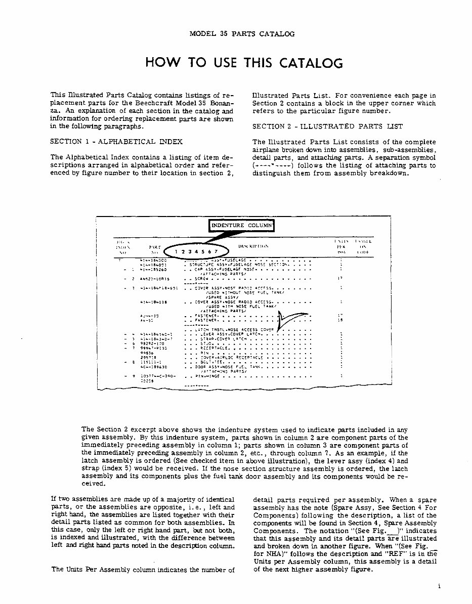
MODEL 35 PARTS CATALOG HOW TO USE THIS CAIALOC This Illustrated Parts Catalog contains Listings of re- Illustrated Parts List. For convenience each page in placement parts far the Beechcraft Mode135 Bonan- Section 2 contains a block in the upper corner which za. An explanation of each section in the catalog and refers to the particular fi~ure number. information for ordering replacement parts are shown in the following paragraphs. SECTION 2 ILLUSTRATED PARTS LIST SECTION 1 ALPHABETICAL INDEX The Illustrated Parts List consists of the complete airplane broken down into assemblies, sub-assemblies, The Alphabetical Index contains a listing of item de- detail parts, and attaching parts. A separation symbol scriptions arranged in alphabetical order and refer- (----’----) follows the listing of attaching parts to enced by figure number to their location in section 2, distinguish them from assembly breakdown. Ih’DENTURE COLUMN P\KI~~ I’IK \(l( 1 t345671 ~´•~ 1(1111 *!c-1BL:05 -.5’1 .FI1SEL’GT L!c~i~sO~l .SlgUCTV"t LSS*´•F~SELIGE ~3SE SFC.l;h::::: ilL-~BSZb5 .. C´•P LSSI´•EULELnGF ~CSi´• . ´• ....... ´• ,n~:~C*INC ~n?~S/ ~*523-ICR16 .. SC9lr .. .......... ´• . 17 iii-18crl8-b~: .. ’:VEI nSSr.rCS" R1~!^ ´•CC’S~. iuS~D rlr*0vl r3SE CJI- :nu~;’’’’‘ ~SDnsE nSS*l *!~-IBcOlB ..;OVES *SS*~*OSE a´•01: n::ISS........ IvSED *ir~ *OSE FUEL TIN~I Ii;rnC~I~G o´•STSI nJ-i-1: .. EISli~E9´• ´• ´• r ´• ´• ´• ´• ´• ~i-13 .. F´•gr~NEs. .......... :9 .. Lnr;3 InSr~.nOSi nCCESS:"vEr Lli-ls~~~c-? ... ,LVE~ 1SSI.COVEF ~1~C,. ........ iii-LILJiO-7 .. ´• 5T910.C:V(9 CD1Cn 98292-1:0 ... STU:´• 999Li-011; ... sICED:~CLE. .............. ´• 9093, ... D!H ~2~´•.´•l;,l 19s~!e ... :SVE~´•;I9~3C ... Jil:.IEE. .... *CL-!8963C 500a nSS*.NOSi FUE~ :19~.. ´• ´• ´• ´• ´• ´• I~~:ac*lu~ ~n~rSI iOSl’c-C-JPa- .. ~ln´•*~NGF LS231) The Section 2 excerpt above shows the indenture system used to indicate parts included in any given assembly. BF this indenture system, parts shown in column 2 are component parts of the immediately preceding assembly in column 1; parts shown in column 3 are component parts of the immediately preceding assembly in column 2, etc., through column 7. As an example, if the latch assembly is ordered (See checked item in above illustration), the lever assy tinder 4) and strap tinder 5) would be received. If the nose section structure assembly is ordered, the latch assembly and its components plus the fuel tank door assembly and its components would be re- ceived. If two assemblies are made up of a majority of identical detail parts required per assembly. ~iihen a spare parts, or the assemblies are opposite, i.e., left and assembly has the note (Spare Assy, See Section 4 For right hand, the assemblies are Listed together with their Components) following the description, a list of the detail parts listed as common for both assemblies. Tn components will he found in Section 4, Spare Assembly this case, only the left or right hand part, but not both, Components. The notation "(See Fig. )" indicates is indexed and illustrated, with the difference between that this assembly and its detail parts are illustrated left and right hand parts noted in the description column. and broken down in another figure. When "(See Fig. for NHA)" follows the description and "REF" is in the Units per Assembly column, this assembly is a detail The Units eer Assembly column indicates the number of of the next higher assembly figure.
The Beechcraft Bonanza 35 Series Aircrafts Parts Catalog covers the following models:
H35
J35
K35
M35
N35
P35
S35
V35
V35TC
V35A
V35A-TC
The catalog provides a systematic inventory of essential components and assemblies for the specified models. It includes detailed parts illustrations, part numbers, and descriptions, facilitating quick and accurate identification and sourcing of replacement parts.
Organized into logical sections, the catalog covers specific assemblies such as the airframe, landing gear, electrical systems, and engine accessories. Exploded diagrams offer visual clarification and context, aiding in understanding how different parts fit together for maintenance or overhaul.
Whether for routine repairs or major restorations, this authoritative parts catalog serves as an invaluable reference for maintaining aircraft performance and safety by ensuring the correct parts are selected and installed.
Printable: Yes Language: English Compatibility: Pretty much any electronic device, including PC, Mac computers, Android, and Apple smartphones and tablets, etc. Requirements: Adobe Reader (free)
Recently Viewed
5,521,897Happy Clients
2,594,462eManuals
1,120,453Trusted Sellers
15Years in Business
Price:
Actual Price:
Beechcraft Bonanza 35 Series Aircrafts (H35/J35/K35/M35/N35/P35/S35/V35/V35TC/V35A/V35A-TC) Parts Catalog