EAS20070 NOTICE This manual was produced by MBK Industrie. primarily for use by Yamaha dealers and their qualified mechanics. It is not possible to include all the knowledge of a mechanic in one manual. Therefore, any- one who uses this book to perform maintenance and repairs on Yamaha vehicles should have a basic understanding of mechanics and the techniques to repair these types of vehicles. Repair and mainte- nance work attempted by anyone without this knowledge is likely to render the vehicle unsafe and unfit for use. Yamaha Motor Company, Ltd. is continually striving to improve all of its models. Modifications and sig- nificant changes in specifications or procedures will be forwarded to all authorized Yamaha dealers and will appear in future editions of this manual where applicable. NOTE: Designs and specifications are subject to change without notice. EAS20080 IMPORTANT MANUAL INFORMATION Particularly important information is distinguished in this manual by the following. The Safety Alert Symbol means ATTENTION! BECOME ALERT! YOUR SAFETY IS INVOLVED! Failure to follow WARNING instructions could result in severe injury or death to the vehicle operator, a bystander or a person checking or repairing the ve- hicle. A CAUTION indicates special precautions that must be taken to avoid dam- age to the vehicle. A NOTE provides key information to make procedures easier or clearer. WARNING CAUTION: NOTE:
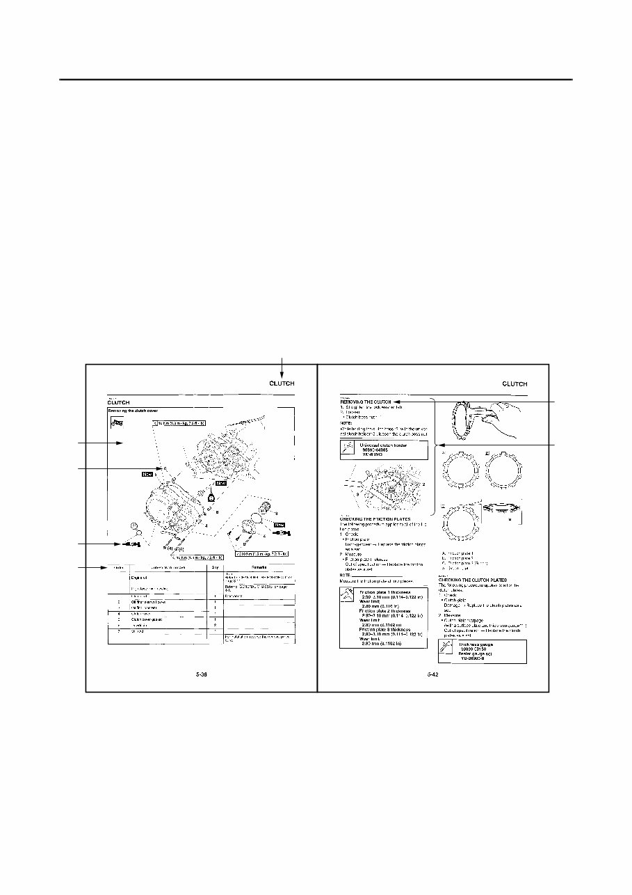
EAS20090 HOW TO USE THIS MANUAL This manual is intended as a handy, easy-to-read reference book for the mechanic. Comprehensive explanations of all installation, removal, disassembly, assembly, repair and check procedures are laid out with the individual steps in sequential order. • The manual is divided into chapters and each chapter is divided into sections. The current section title “1” is shown at the top of each page. • Sub-section titles “2” appear in smaller print than the section title. • To help identify parts and clarify procedure steps, there are exploded diagrams “3” at the start of each removal and disassembly section. • Numbers “4” are given in the order of the jobs in the exploded diagram. A number indicates a disas- sembly step. • Symbols “5” indicate parts to be lubricated or replaced. Refer to “SYMBOLS”. • A job instruction chart “6” accompanies the exploded diagram, providing the order of jobs, names of parts, notes in jobs, etc. • Jobs “7” requiring more information (such as special tools and technical data) are described sequen- tially. 1 7 3 4 5 6 2
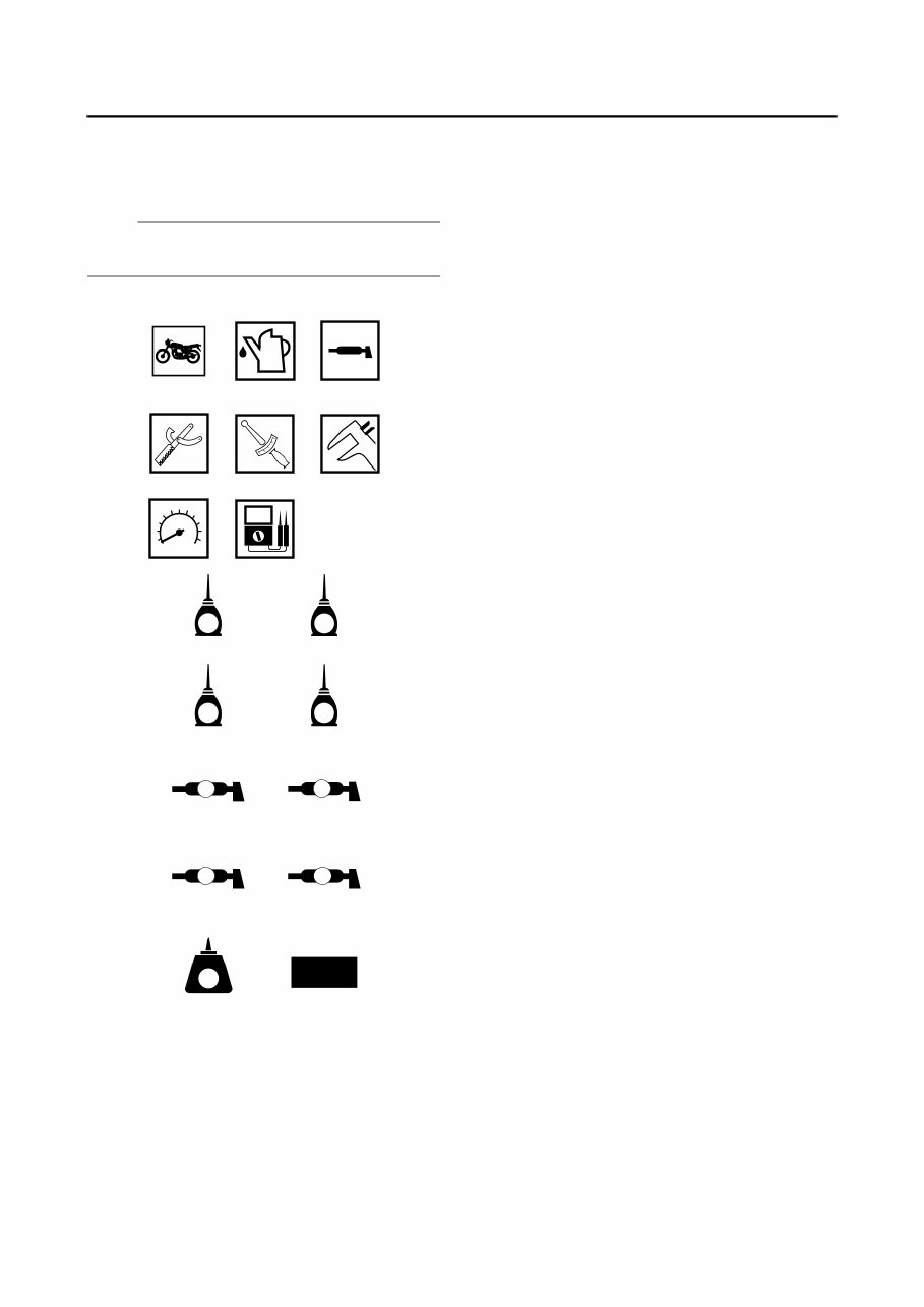
EAS20100 SYMBOLS The following symbols are used in this manual for easier understanding. NOTE: The following symbols are not relevant to every vehicle. G M E B LS M 9 10 11 12 13 14 15 16 17 18 LT New BF S T R . . 1 2 3 4 5 6 7 8 1. Serviceable with engine mounted 2. Filling fluid 3. Lubricant 4. Special tool 5. Tightening torque 6. Wear limit, clearance 7. Engine speed 8. Electrical data 9. Engine oil 10. Gear oil 11. Molybdenum disulfide oil 12. Brake fluid 13. Wheel bearing grease 14.Lithium-soap-based grease 15.Molybdenum disulfide grease 16. Silicone grease 17.Apply locking agent (LOCTITE®). 18. Replace the part with a new one.
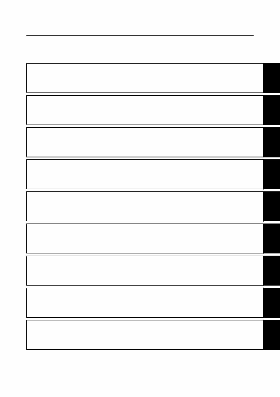
EAS20110 TABLE OF CONTENTS GENERAL INFORMATION 1 SPECIFICATIONS 2 PERIODIC CHECKS AND ADJUSTMENTS 3 CHASSIS 4 ENGINE 5 COOLING SYSTEM 6 FUEL SYSTEM 7 ELECTRICAL SYSTEM 8 TROUBLESHOOTING 9
1 GENERAL INFORMATION IDENTIFICATION ............................................................................................ 1-1 VEHICLE IDENTIFICATION NUMBER ..................................................... 1-1 MODEL LABEL.......................................................................................... 1-1 FEATURES ...................................................................................................... 1-2 OUTLINE OF THE FI SYSTEM ................................................................. 1-2 FI SYSTEM................................................................................................ 1-3 MULTI-FUNCTION DISPLAY .................................................................... 1-4 IMPORTANT INFORMATION ......................................................................... 1-5 PREPARATION FOR REMOVAL AND DISASSEMBLY........................... 1-5 REPLACEMENT PARTS........................................................................... 1-5 GASKETS, OIL SEALS AND O-RINGS .................................................... 1-5 LOCK WASHERS/PLATES AND COTTER PINS ..................................... 1-5 BEARINGS AND OIL SEALS .................................................................... 1-6 CIRCLIPS .................................................................................................. 1-6 CHECKING THE CONNECTIONS .................................................................. 1-7 SPECIAL TOOLS ............................................................................................ 1-8
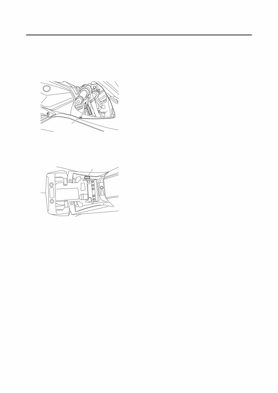
IDENTIFICATION 1-1 EAS20130 IDENTIFICATION EAS20140 VEHICLE IDENTIFICATION NUMBER The vehicle identification number “1” is stamped into the right side of the steering head pipe. EAS20150 MODEL LABEL The model label “1” is affixed to the frame. This information will be needed to order spare parts. 1 1
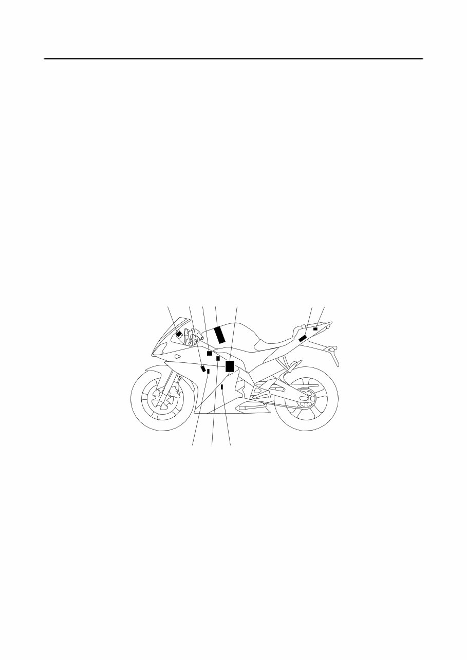
FEATURES 1-2 EAS20170 FEATURES EAS5D71022 OUTLINE OF THE FI SYSTEM The main function of a fuel supply system is to provide fuel to the combustion chamber at the optimum air-fuel ratio in accordance with the engine operating conditions and the atmospheric temperature. In the conventional carburetor system, the air-fuel ratio of the mixture that is supplied to the combustion chamber is created by the volume of the intake air and the fuel that is metered by the jet used in the respective carburetor. Despite the same volume of intake air, the fuel volume requirement varies by the engine operating con- ditions, such as acceleration, deceleration, or operating under a heavy load. Carburetors that meter the fuel through the use of jets have been provided with various auxiliary devices, so that an optimum air- fuel ratio can be achieved to accommodate the constant changes in the operating conditions of the en- gine. As the requirements for the engine to deliver more performance and cleaner exhaust gases increase, it becomes necessary to control the air-fuel ratio in a more precise and finely tuned manner. To accom- modate this need, this model has adopted an electronically controlled fuel injection (FI) system, in place of the conventional carburetor system. This system can achieve an optimum air-fuel ratio required by the engine at all times by using a microprocessor that regulates the fuel injection volume according to the engine operating conditions detected by various sensors. The adoption of the FI system has resulted in a highly precise fuel supply, improved engine response, better fuel economy, and reduced exhaust emissions. 9 10 11 1 2 3 4 5,6 7 8 1. Engine trouble warning light 2. Spark plug 3. Ignition coil 4. Fuel pump 5. FID (fast idle solenoid) 6. Throttle body sensor assembly (consisting of throttle position sensor, intake air pressure sensor, intake air temperature sensor) 7. ECU (engine control unit) 8. Lean angle sensor 9. Crankshaft position sensor 10. Fuel injector 11.Coolant temperature sensor
Get the complete official full factory service repair manual for the 2008-2015 Yamaha YZF-R125. This manual provides step-by-step instructions based on the complete disassembly of the machine, along with detailed substeps, notes, cautions, and warnings throughout each chapter. It includes hundreds of pages covering all styles and is specifically written for both do-it-yourselfers and experienced mechanics.
The manual covers:
General Information
Fuel system
Cooling system
Engine top end
Clutch
Engine lubrication system
Engine Removal /Installation
Crankshaft/ Transmission
Wheels/Tires
Final Drive
Brakes
Suspension
Steering
Frame
Electrical System
Appendix
This manual is available in PDF format and provides detailed illustrations, drawings, and photos to guide you through every procedure. It also makes it easy to diagnose and repair problems with your machine's electrical system, with troubleshooting and electrical service procedures combined with detailed wiring diagrams for ease of use.
Language: English
Delivery: Link will appear on the checkout page after payment is complete.
Requirements: Adobe Reader
Get your 2008-2015 Yamaha YZF-R125 Service & Repair Manual now and keep your vehicle working properly!