Kymco UXV500 UXV 500 Utility Vehicle Service Repair Workshop Manual
What's Included?
Lifetime Access
Fast Download Speeds
Online & Offline Access
Access PDF Contents & Bookmarks
Full Search Facility
Print one or all pages of your manual
UXV 500 By KWANG YANG Motor Co., Ltd. First Edition, Feb 2008 All rights reserved. Any reproduction or unauthorized use without the written permission of KWANG YANG Motor Co., Ltd. is expressly prohibited. T100-UAA0AA-US
UXV 500 PREFACE This Service Manual describes the technical features and servicing procedures for the UXV 500. Section 1 contains the precautions for all operations stated in this manual. Read them carefully before any operation is started. Section 2 is the removal/installation procedures for the frame covers which are subject to higher removal/installation frequency during maintenance and servicing operations. Section 3 describes the inspection/ adjustment procedures, safety rules and service information for each part, starting from periodic maintenance. Sections 4 through 12 give instructions for disassembly, assembly and adjustment of engine parts. Section 13 through 16 is the removal/ installation of chassis. Section 17 through 21 states the testing and measuring methods of electrical equipment. Most sections start with an assembly or system illustration and troubleshooting for the section. The subsequent pages give detailed procedures for the section. KWANG YANG MOTOR CO., LTD. Quality Technology Division Overseas Service Department TABLE OF CONTENTS GENERAL INFORMATION 1 FRAME COVERS /EXHAUST MUFFLER 2 INSPECTION/ADJUSTMENT 3 LUBRICATION SYSTEM 4 FUEL SYSTEM 5 COOLING SYSTEM 6 ENGINE REMOVAL 7 CYLINDER HEAD/VALVES 8 CYLINDER/PISTON 9 DRIVE PULLEY/DRIVEN PULLEY/ CLUTCH 10 FINAL REDUCTION/ TRANSMISSION SYSTEM 11 LEFT CRANKCASE/CRANKSHAFT/ BALANCE SHAFT 12 DRIVE TRAIN 13 FRONT WHEEL/FRONT SUSPENSION/ STTEERING SYSTEM 14 REAR WHEEL/AXLE/SHOCK ABSORBER/SWING ARM 15 BRAKE SYSTEM 16 BATTERY/CHARGING SYSTEM 17 IGNITION SYSTEM 18 STARTER SYSTEM 19 LIGHTS/ SWITCHES 20 WIRING DIAGRAMS 21 The information and contents included in this manual may be different from the vehicle in case specifications are changed. KYMCO reserves the right to make changes at any time without notice and without incurring any obligation. CHASSIS ELECTRICAL EQUIPMENT ENGINE
1. GENERAL INFORMATION 1-0 UXV 500 __________________________________________________________________________________ __________________________________________________________________________________ __________________________________________________________________________________ __________________________________________________________________________________ __________________________________________________________________________________ GENERAL INFORMATION __________________________________________________________________________________ SERIAL NUMBER---------------------------------------------------------- 1- 1 SPECIFICATIONS ---------------------------------------------------------- 1- 2 SERVICE PRECAUTIONS ------------------------------------------------ 1- 3 TORQUE VALUES --------------------------------------------------------- 1-11 SPECIAL TOOLS ----------------------------------------------------------- 1-15 LUBRICATION POINTS -------------------------------------------------- 1-18 1
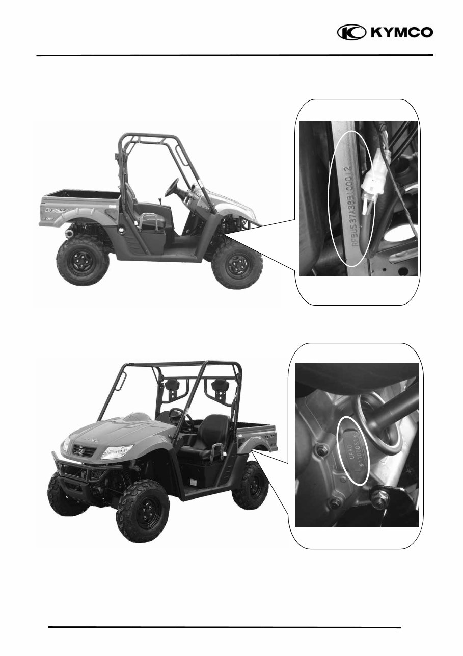
1. GENERAL INFORMATION 1-1 UXV 500 SERIAL NUMBER (1) Location of Engine Serial Number (1) Location of Frame Serial Number
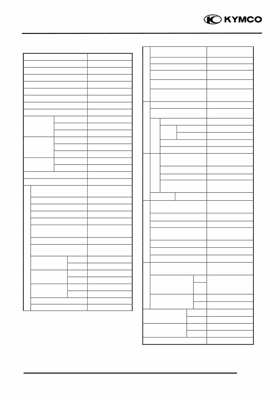
1. GENERAL INFORMATION 1-2 UXV 500 SPECIFICATIONS Model No. UAA0 Name & Type UXV 500 Overall length 2870 mm Overall width 1500 mm Overall height 1850 mm Wheel base 1910 mm Engine type D.O.H.C. Displacement 498.5 CC Fuel used Nonleaded Gasoline Front wheel 228 kg Rear wheel 297kg Dry weight Total 525kg Front wheel 243 kg Rear wheel 317 kg Curb weight Total 560 kg Front wheel 25X8R-12 Tires Rear wheel 25X10R-12 Ground clearance 235 mm (9.4 in) Min. turning radius 3350 mm (134 in) Starting system Electric/Recoil starter Type Gasoline, 4-stroke Cylinder arrangement Single cylinder Combustion chamber type Semi-sphere Valve arrangement O.H.C., chain drive Bore x stroke 92X75 mm (3.68X3 in) Compression ratio 10.5:1 Compression pressure 15 kgf/cm² (1500kPa, 213 psi) Opens 5° BTDC Intake valve (at 1mm lift) Closes 45° ABDC Opens 45° BBDC Exhaust valve (at 1mm lift) Closes 5° ATDC Intake 0.1 mm (0.004 in) Valve clearance (cold) Exhaust 0.1 mm (0.004 in) Idle speed (rpm) 1500 rpm Cooling type Liquid cooled Lubrication type Forced pressure & Wet sump Oil pump type Trochoid Oil filter type Full-flow filtration Oil capacity 3.6 L Oil exchanging capacity 3 L After draining and oil filter cartridge change 3.2 L Air cleaner type & No Wet type element Fuel capacity 17 L Type CVK ON ROAD #122 Main jet OFF ROAD #130 Slow jet #40 Choke jet #90 Type Full transistor digital ignition Ignition timing 5°/1500 rpm Spark plug CR7E (NGK) Spark plug gap 0.9mm Battery Capacity 12V18AH Clutch type Wet, centrifugal automatic Clutch operation system Automatic (V-belt) Primary reduction system V-belt Secondary reduction system Shaft drive High reduction ratio 3.76 Low reduction ratio 6.464 Reverse ratio 5.31 FR/RR tire rolling circumference 1995/1995 mm (79.8/79.8 in) Front Tire pressure (1person 75kg) Rear 0.7/0.98 kgf/cm² (28 Kpa, 3.2 psi) Left 36° Turning angle Right 36° Front Disk brake Brake system type Rear Disk brake Front Double wishbone Suspension type Rear Unit swing Frame type Double cradle Engine Ignition System Drive Train Moving Device Lubrication System Fuel System Carburetor Electrical Equipment
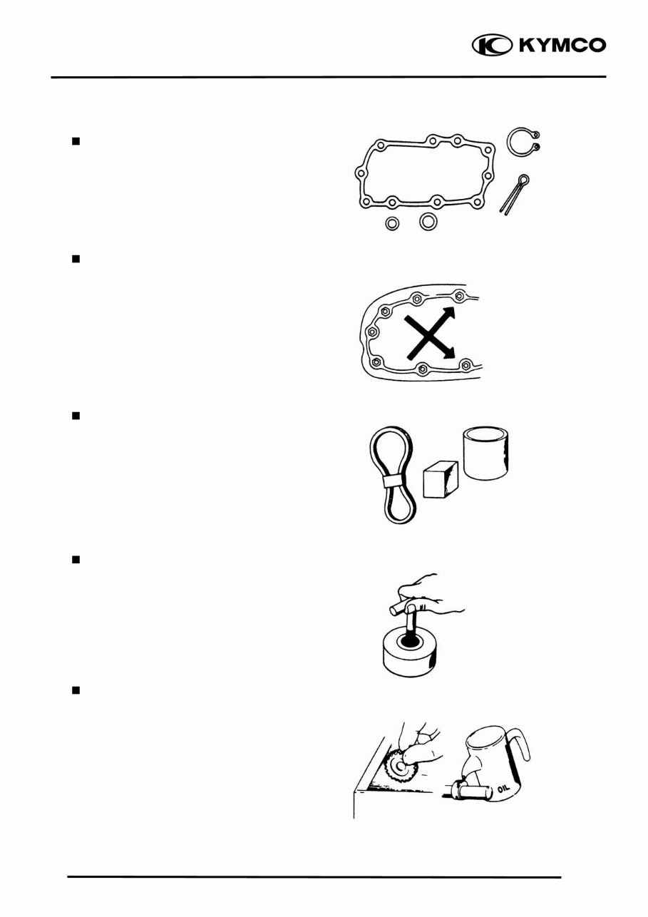
1. GENERAL INFORMATION 1-3 UXV 500 SERVICE PRECAUTIONS Make sure to install new gaskets, O-rings, circlips, cotter pins, etc. when reassembling. When tightening bolts or nuts, begin with larger-diameter to smaller ones at several times, and tighten to the specified torque diagonally. Use genuine parts and lubricants. When servicing the motorcycle, be sure to use special tools for removal and installation. After disassembly, clean removed parts. Lubricate sliding surfaces with engine oil before reassembly.
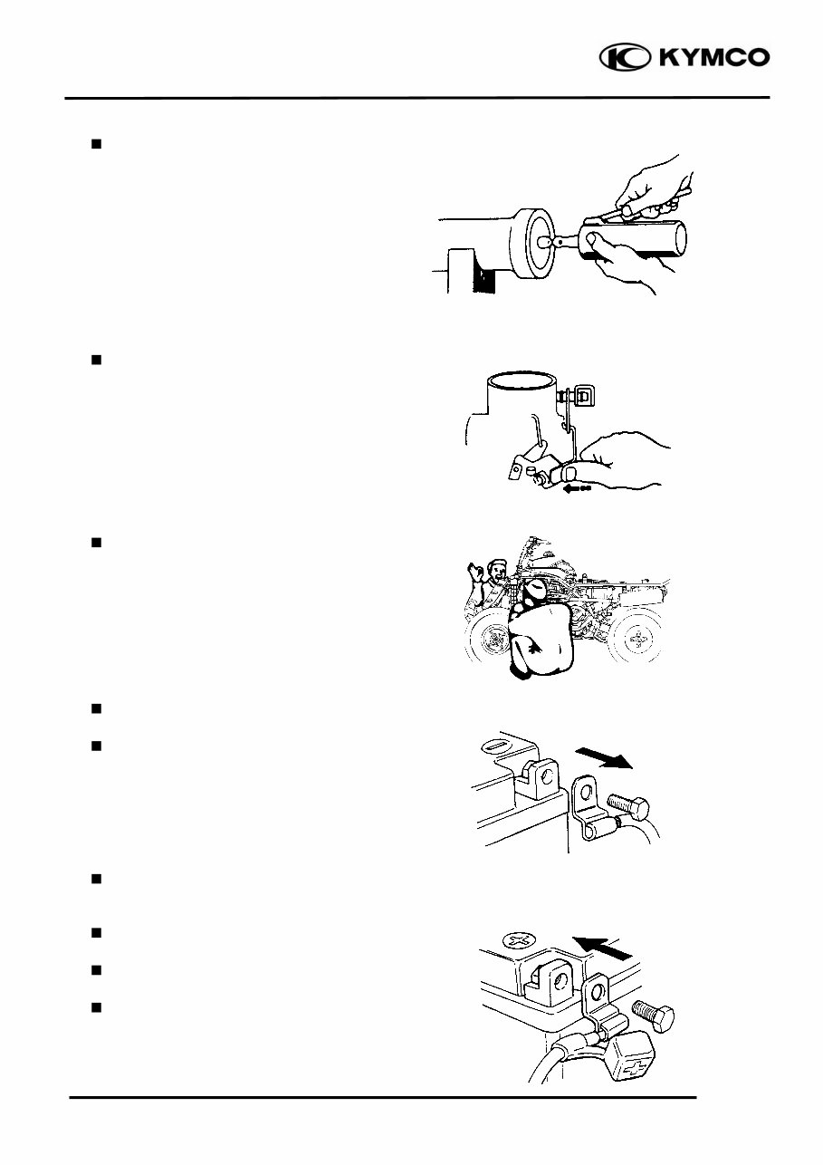
1. GENERAL INFORMATION 1-4 UXV 500 Apply or add designated greases and lubricants to the specified lubrication points. After reassembly, check all parts for proper tightening and operation. When two persons work together, pay attention to the mutual working safety. Disconnect the battery negative (-) terminal before operation. When using a spanner or other tools, make sure not to damage the motorcycle surface. After operation, check all connecting points, fasteners, and lines for proper connection and installation. When connecting the battery, the positive (+) terminal must be connected first. After connection, apply grease to the battery terminals. Terminal caps shall be installed securely.
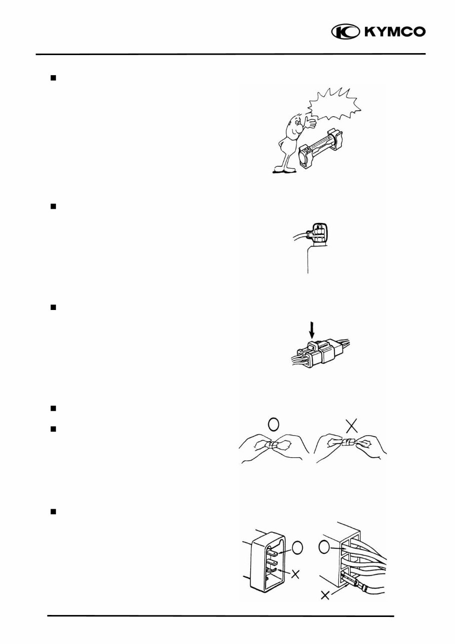
1. GENERAL INFORMATION 1-5 UXV 500 If the fuse is burned out, find the cause and repair it. Replace it with a new one according to the specified capacity. After operation, terminal caps shall be installed securely. When taking out the connector, the lock on the connector shall be released before operation. Hold the connector body when connecting or disconnecting it. Do not pull the connector wire. Check if any connector terminal is bending, protruding or loose. Confirm Capacity
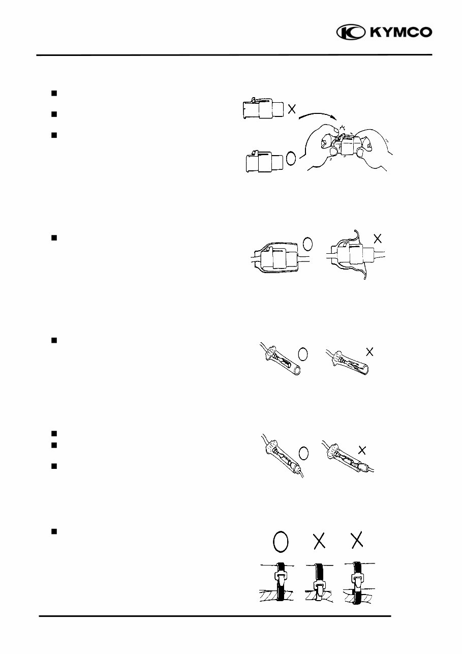
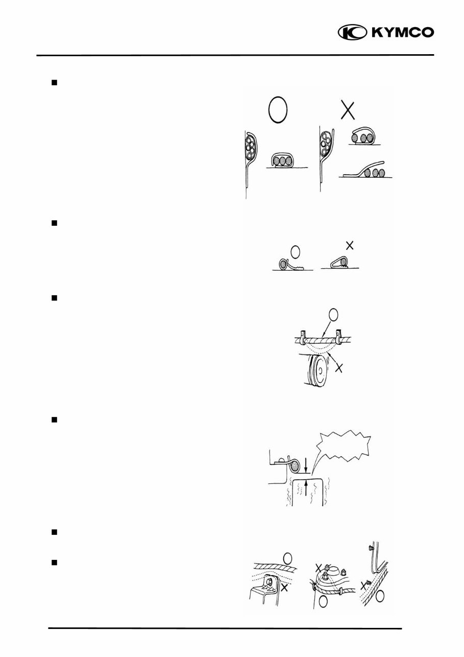
1. GENERAL INFORMATION 1-6 UXV 500 The connector shall be inserted completely. If the double connector has a lock, lock it at the correct position. Check if there is any loose wire. Before connecting a terminal, check for damaged terminal cover or loose negative terminal. Check the double connector cover for proper coverage and installation. Insert the terminal completely. Check the terminal cover for proper coverage. Do not make the terminal cover opening face up. Secure wire harnesses to the frame with their respective wire bands at the designated locations. Tighten the bands so that only the insulated surfaces contact the wire harnesses. Snapping!
1. GENERAL INFORMATION 1-7 UXV 500 After clamping, check each wire to make sure it is secure. Do not squeeze wires against the weld or its clamp. After clamping, check each harness to make sure that it is not interfering with any moving or sliding parts. When fixing the wire harnesses, do not make it contact the parts which will generate high heat. Route wire harnesses to avoid sharp edges or corners. Avoid the projected ends of bolts and screws. Route wire harnesses passing through the side of bolts and screws. Avoid the projected ends of bolts and screws. No Contact !
This is a complete service repair manual for the Kymco UXV500 UXV 500 Utility Vehicle. These manuals cover a wide range of topics including engine, general information, transmission, chassis, lighting, steering, seats system, clutch, suspension, locks, brakes, lubrication, electrical, frame fuel system, and battery, among others. They are useful for both professional mechanics and DIY enthusiasts. The manuals are available in Adobe Acrobat format and are compatible with both PC and Mac. You can easily print out the specific section you need and dispose of it after use, or print the entire manual and keep it in a 3-ring binder for reference. Instant delivery ensures no waiting for a CD to arrive via mail. Please note that high-speed internet connection is recommended for downloading due to large file sizes. For other similar manuals, please message us for availability.