2006 Yamaha Stratoliner Roadliner XV19/XV1900 Service & Repair Manual
What's Included?
Lifetime Access
Fast Download Speeds
Online & Offline Access
Access PDF Contents & Bookmarks
Full Search Facility
Print one or all pages of your manual
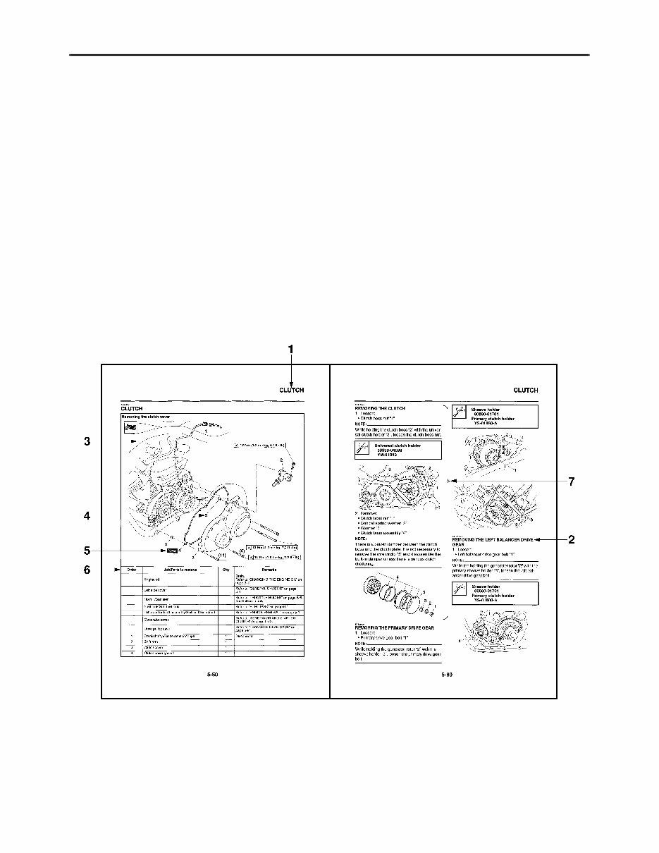
EAS20090 HOW TO USE THIS MANUAL This manual is intended as a handy, easy-to-read reference book for the mechanic. Comprehensive explanations of all installation, removal, disassembly, assembly, repair and check procedures are laid out with the individual steps in sequential order. • The manual is divided into chapters and each chapter is divided into sections. The current section title is shown at the top of each page “1”. • Sub-section titles “2” appear in smaller print than the section title. • To help identify parts and clarify procedure steps, there are exploded diagrams “3” at the start of each removal and disassembly section. • Numbers “4” are given in the order of the jobs in the exploded diagram. A number indicates a disas- sembly step. • Symbols “5” indicate parts to be lubricated or replaced. Refer to “SYMBOLS”. • A job instruction chart “6” accompanies the exploded diagram, providing the order of jobs, names of parts, notes in jobs, etc. • Jobs “7” requiring more information (such as special tools and technical data) are described sequen- tially.
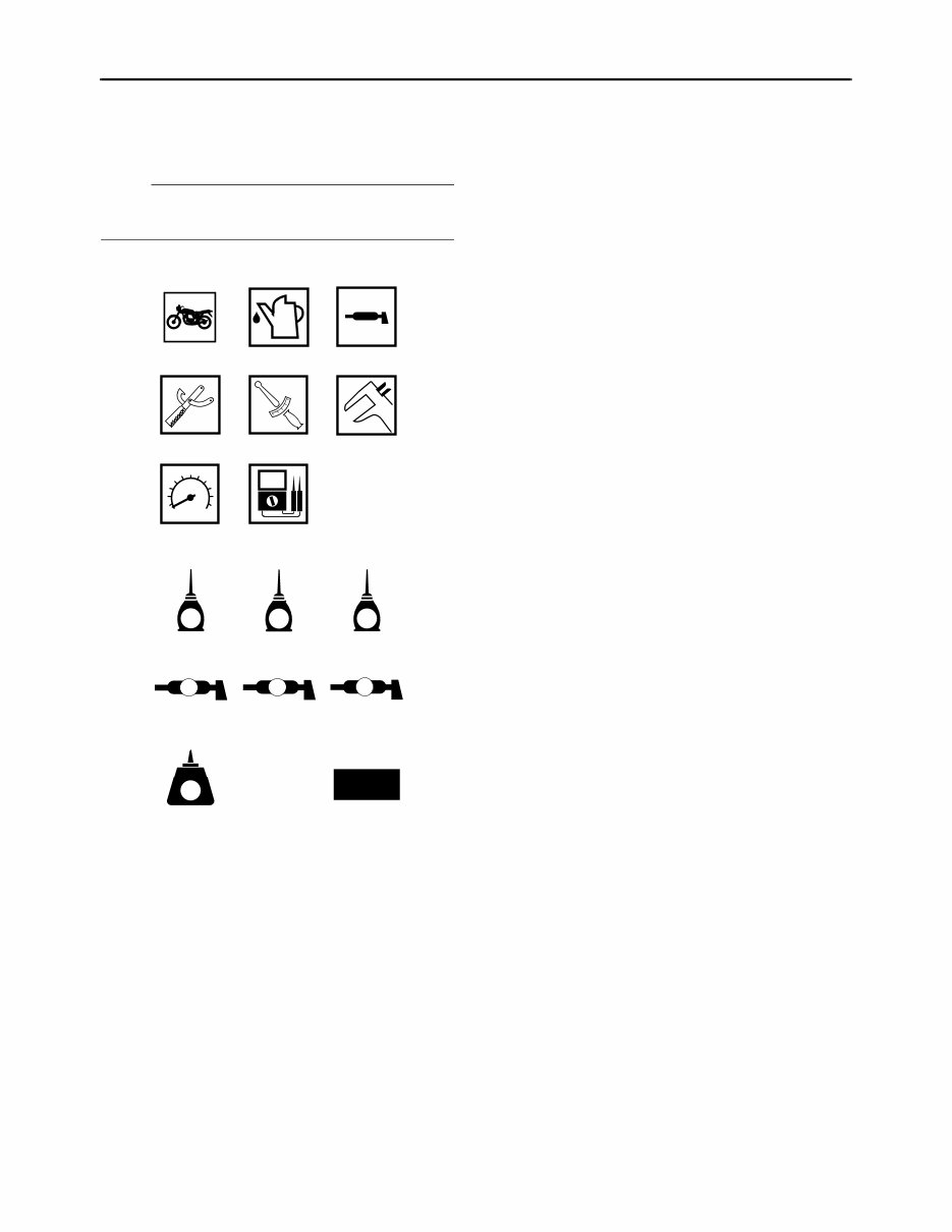
EAS20100 SYMBOLS The following symbols are used in this manual for easier understanding. NOTE: The following symbols are not relevant to every vehicle. G M E B LS M 9 10 11 12 13 14 15 16 LT New T R . . 1 2 3 4 5 6 7 8 1. Serviceable with engine mounted 2. Filling fluid 3. Lubricant 4. Special tool 5. Tightening torque 6. Wear limit, clearance 7. Engine speed 8. Electrical data 9. Engine oil 10. Gear oil 11.Molybdenum-disulfide oil 12. Wheel-bearing grease 13.Lithium-soap-based grease 14.Molybdenum-disulfide grease 15.Apply locking agent (LOCTITE ® ) 16. Replace the part
EAS20110 TABLE OF CONTENTS GENERAL INFORMATION 1 SPECIFICATIONS 2 PERIODIC CHECKS AND ADJUSTMENTS 3 CHASSIS 4 ENGINE 5 FUEL SYSTEM 6 ELECTRICAL SYSTEM 7 TROUBLESHOOTING 8
1 GENERAL INFORMATION IDENTIFICATION ............................................................................................ 1-1 VEHICLE IDENTIFICATION NUMBER..................................................... 1-1 MODEL LABEL ......................................................................................... 1-1 FEATURES ..................................................................................................... 1-2 OUTLINE OF THE FI SYSTEM................................................................. 1-2 FI SYSTEM ............................................................................................... 1-3 INSTRUMENT FUNCTIONS..................................................................... 1-4 IMPORTANT INFORMATION ......................................................................... 1-8 PREPARATION FOR REMOVAL AND DISASSEMBLY .......................... 1-8 REPLACEMENT PARTS .......................................................................... 1-8 GASKETS, OIL SEALS AND O-RINGS .................................................... 1-8 LOCK WASHERS/PLATES AND COTTER PINS..................................... 1-8 BEARINGS AND OIL SEALS.................................................................... 1-9 CIRCLIPS.................................................................................................. 1-9 CHECKING THE CONNECTIONS ................................................................ 1-10 SPECIAL TOOLS .......................................................................................... 1-11
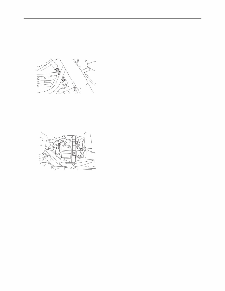
IDENTIFICATION 1-1 EAS20130 IDENTIFICATION EAS20140 VEHICLE IDENTIFICATION NUMBER The vehicle identification number “1” is stamped into the right side of the steering head pipe. EAS20150 MODEL LABEL The model label “1” is affixed to the frame under the rider seat. This information will be needed to order spare parts. 1 1
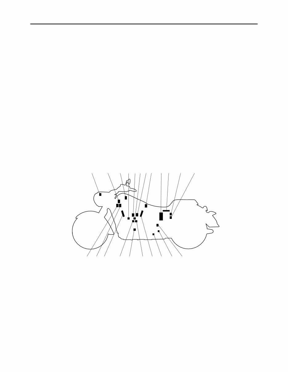
FEATURES 1-2 EAS20170 FEATURES ET1D71017 OUTLINE OF THE FI SYSTEM The main function of a fuel supply system is to provide fuel to the combustion chamber at the optimum air-fuel ratio in accordance with the engine operating conditions and the atmospheric temperature. In the conventional carburetor system, the air-fuel ratio of the mixture that is supplied to the combustion chamber is created by the volume of the intake air and the fuel that is metered by the jet used in the respective carburetor. Despite the same volume of intake air, the fuel volume requirement varies by the engine operating con- ditions, such as acceleration, deceleration, or operating under a heavy load. Carburetors that meter the fuel through the use of jets have been provided with various auxiliary devices, so that an optimum air- fuel ratio can be achieved to accommodate the constant changes in the operating conditions of the en- gine. As the requirements for the engine to deliver more performance and cleaner exhaust gases increase, it becomes necessary to control the air-fuel ratio in a more precise and finely tuned manner. To accom- modate this need, this model has adopted an electronically controlled fuel injection (FI) system, in place of the conventional carburetor system. This system can achieve an optimum air-fuel ratio required by the engine at all times by using a microprocessor that regulates the fuel injection volume according to the engine operating conditions detected by various sensors. The adoption of the FI system has resulted in a highly precise fuel supply, improved engine response, better fuel economy, and reduced exhaust emissions. 1 2 20 21 3 4 5678 9 10 11 12 14 13 16 19 18 17 16 15 1. Air temperature sensor 2. ISC (idle speed control) unit 3. Cylinder-#2 intake air pressure sensor 4. Engine temperature sensor 5. Cylinder-#1 right ignition coil 6. Throttle position sensor 7. Cylinder-#1 left ignition coil 8. Cylinder-#1 intake air pressure sensor 9. Fuel pump 10. ECU (electronic control unit) 11.Relay unit (fuel pump relay) 12. EXUP servo motor 13. Speed sensor 14.O 2 sensor 15. Lean angle sensor 16. Spark plug 17. Injector #1 18.Crankshaft position sensor 19. Injector #2 20.Cylinder-#2 right ignition coil 21.Cylinder-#2 left ignition coil
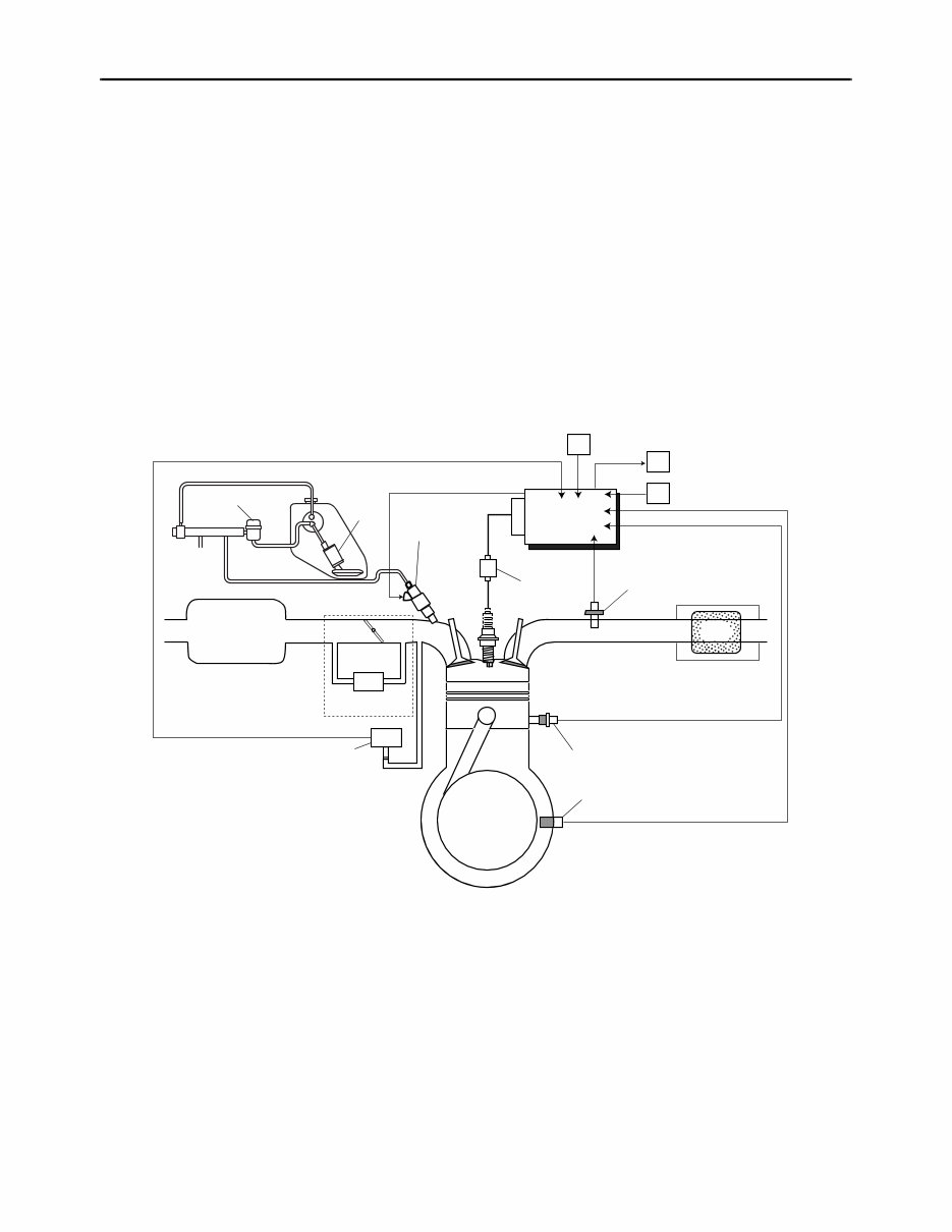
FEATURES 1-3 ET1D71018 FI SYSTEM The fuel pump delivers fuel to the fuel injector via the fuel filter. The pressure regulator maintains the fuel pressure that is applied to the fuel injector at only 392 kPa (3.92 kg/cm², 55.7 psi). Accordingly, when the energizing signal from the ECU energizes the fuel injector, the fuel passage opens, causing the fuel to be injected into the intake manifold only during the time the passage remains open. There- fore, the longer the length of time the fuel injector is energized (injection duration), the greater the vol- ume of fuel that is supplied. Conversely, the shorter the length of time the fuel injector is energized (injection duration), the lesser the volume of fuel that is supplied. The injection duration and the injection timing are controlled by the ECU. Signals that are input from the throttle position sensor, crankshaft position sensor, intake air pressure sensor, air temperature sensor, engine temperature sensor, speed sensor and O 2 sensor enable the ECU to determine the injection duration. The injection timing is determined through the signals from the crankshaft position sensor. As a result, the volume of fuel that is required by the engine can be supplied at all times in accordance with the driving conditions. Illustration is for reference only. 15 A 1 2 3 4 C 5 8 7 6 10 11 12 13 14 B #1 #2 9 1. Pressure regulator 2. Fuel pump 3. Fuel injector 4. Ignition coil 5. ECU (electronic control unit) 6. Air temperature sensor 7. ISC (idle speed control) unit 8. Throttle position sensor 9. O 2 sensor 10. Catalytic converter 11.Engine temperature sensor 12.Crankshaft position sensor 13.Intake air pressure sensor 14. Throttle body 15. Air filter case A. Fuel system B. Air system C. Control system
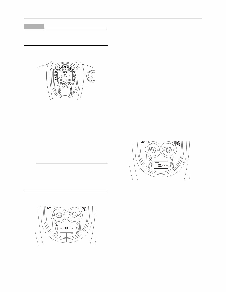
FEATURES 1-4 ET1D71036 INSTRUMENT FUNCTIONS Multi-function meter unit WARNING EW1D71008 Be sure to stop the vehicle before making any setting changes to the multi-function meter unit. The multi-function meter unit is equipped with the following: • a speedometer (which shows the riding speed) • a tachometer (which shows the engine speed) • a fuel gauge • an odometer (which shows the total distance traveled) • two tripmeters (which show the distance trav- eled since they were last set to zero) • a fuel reserve tripmeter (which shows the dis- tance traveled on the fuel reserve) • a clock • a self-diagnosis device • a brightness control mode NOTE: • Be sure to turn the key to “ON” before using the “SELECT” and “RESET” switches. • To switch the odometer, the tripmeters and the fuel reserve tripmeter displays between kilo- meters and miles, press the “SELECT” switch for at least two seconds. (For USA and Califor- nia only) Speedometer The speedometer shows the riding speed. When the key is turned to “ON”, the speedome- ter needle will sweep once across the speed range and then return to zero in order to test the electrical circuit. Tachometer The electric tachometer allows the rider to mon- itor the engine speed and keep it within the ideal power range. When the key is turned to “ON”, the tachometer needle will sweep once across the r/min range and then return to zero r/min in order to test the electrical circuit. 1. Speedometer 2. Fuel gauge 3. Odometer/tripmeter/fuel reserve tripmeter/clock 4. Tachometer 2 3 1 4 1. “SELECT” switch 2. “RESET” switch 1. Speedometer 1. Tachometer 2. Tachometer red zone 2 1 1 2 1
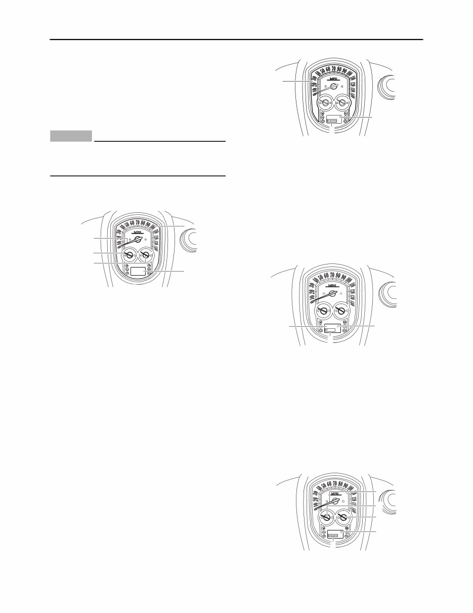
FEATURES 1-5 CAUTION: EC1D71017 Do not operate the engine in the tachometer red zone. Red zone: 5000 r/min and above Fuel gauge The fuel gauge indicates the amount of fuel in the fuel tank. The needle moves towards “E” (Empty) as the fuel level decreases. When the needle reaches “E”, approximately 3.0 L (0.79 US gal) (0.66 Imp.gal) remain in the fuel tank. If this occurs, refuel as soon as possible. When the key is turned to “ON”, the fuel gauge needle will sweep once across the fuel level range and then return to the current amount in order to test the electrical circuit. NOTE: • Do not allow the fuel tank to empty itself com- pletely. • The fuel gauge does not indicate the correct fuel level for the first 5 km/h (3 mi/h) after refu- eling. Odometer, tripmeter, and clock modes Push the “SELECT” switch to switch the display between the odometer mode “ODO”, the tripme- ter modes “TRIP 1” and “TRIP 2” and the clock mode in the following order: ODO → TRIP 1 → TRIP 2 → Clock → ODO If the fuel level warning light comes on, the odometer display will automatically change to the fuel reserve tripmeter mode “F-TRIP” and start counting the distance traveled from that point. In that case, push the “SELECT” switch to switch the display between the various tripme- ter, odometer, and clock modes in the following order: F-TRIP → TRIP 1 → TRIP 2 → Clock → ODO → F-TRIP To reset a tripmeter, select it by pushing the “SE- LECT” switch, and then push the “RESET” switch for at least one second. If you do not reset the fuel reserve tripmeter manually, it will reset itself automatically, and the display will return to the prior mode after refueling and traveling 5 km (3 mi). Clock mode To set the clock: 1. Push the “SELECT” switch to change the dis- play to the clock mode. 2. Push the “SELECT” and “RESET” switches together for at least two seconds. 3. When the hour digits start flashing, push the “RESET” switch to set the hours. 4. Push the “SELECT” switch, and the minute digits will start flashing. 5. Push the “RESET” switch to set the minutes. 6. Push the “SELECT” switch and then release it to start the clock. Self-diagnosis device This model is equipped with a self-diagnosis de- vice for various electrical circuits. 1. Fuel gauge 1. Odometer/tripmeter/fuel reserve tripmeter/clock 1 1 1. Clock 1
FEATURES 1-6 If any of those circuits are defective, the engine trouble warning light will come on, and then the odometer/tripmeter/clock display will indicate a two-digit error code (e.g., 12, 13, 14). If the odometer/tripmeter/clock display indicates any error codes, note the code number, and then check the vehicle. Refer to “FUEL INJEC- TION SYSTEM” on page 7-27. CAUTION: EC1D71018 If the display indicates an error code, the ve- hicle should be checked as soon as possible in order to avoid engine damage. Brightness control mode The brightness can be adjusted for the following: • the multi-function meter unit panel (item num- ber “1”) • the LCD (item number “2”) • the speedometer, tachometer, and the fuel gauge needles (item number “3”) Select the brightness control mode as follows. 1. Turn the key to “OFF”. 2. Push and hold the “SELECT” switch. 3. Turn the key to “ON”, and then release the “SELECT” switch after five seconds. Item number “1” is displayed. 4. Adjust the multi-function meter unit panel brightness level by pushing the “RESET” switch. 5. Push the “SELECT” switch to select the LCD. Item number “2” is displayed. Adjust the LCD brightness level by pushing the “RESET” switch. 6. Push the “SELECT” switch to select the speedometer, tachometer, and the fuel gauge needles. Item number “3” is displayed. Adjust the brightness level of the speedome- ter, tachometer, and the fuel gauge needles by pushing the “RESET” switch. 1. Multi-function meter unit panel 2. LCD 3. Speedometer needle 4. Tachometer needle 5. Fuel gauge needle 2 3 4 5 1 1. Multi-function meter unit panel 2. Item number 3. Brightness level 1. LCD 2. Item number 3. Brightness level 1. Speedometer needle 2. Tachometer needle 2 3 1 2 3 1 4 2 3 1 5
The 2006 Yamaha Stratoliner Roadliner XV19/XV1900 Service & Repair Manual is a comprehensive resource specifically designed for the maintenance and repair of your Yamaha vehicle. This genuine manual is completely bookmarked and searchable, providing technicians and enthusiasts with the same trusted information used in dealership service departments.
The manual covers a wide range of repairs and maintenance topics, including:
General Information and Specifications
Frame and Body
Exhaust System
Maintenance and Lubrication System
Cooling and Fuel Systems
Engine and Clutch
Alternator and Transmission
Front Wheel, Suspension, and Steering
Rear Wheel and Brake Systems
Battery, Charging, and Ignition Systems
Electrical Diagrams, Lights, and Wiring
Troubleshooting Procedures
Featuring detailed illustrations and clear, step-by-step instructions, this manual facilitates the complete disassembly and reassembly of the machine. It is ideally designed for both do-it-yourself enthusiasts and experienced mechanics, with printable pages for easy reference while working in the garage or workshop. Numerous photos and diagrams support every service and repair procedure.
Enjoy instant access to this manual with our secure online delivery system. Upon payment confirmation via our secure processor, you will receive the manual immediately without any shipping delays or additional costs. We accept all major credit/debit cards and PayPal for your convenience.
Recently Viewed
5,521,897Happy Clients
2,594,462eManuals
1,120,453Trusted Sellers
15Years in Business
Price:
Actual Price:
2006 Yamaha Stratoliner Roadliner XV19/XV1900 Service & Repair Manual