

Honda Z50A Shop Manual
What's Included?
Fast Download Speeds
Online & Offline Access
Access PDF Contents & Bookmarks
Full Search Facility
Print one or all pages of your manual
- - ···'--n - - --- --- --
HONDA
Z50A
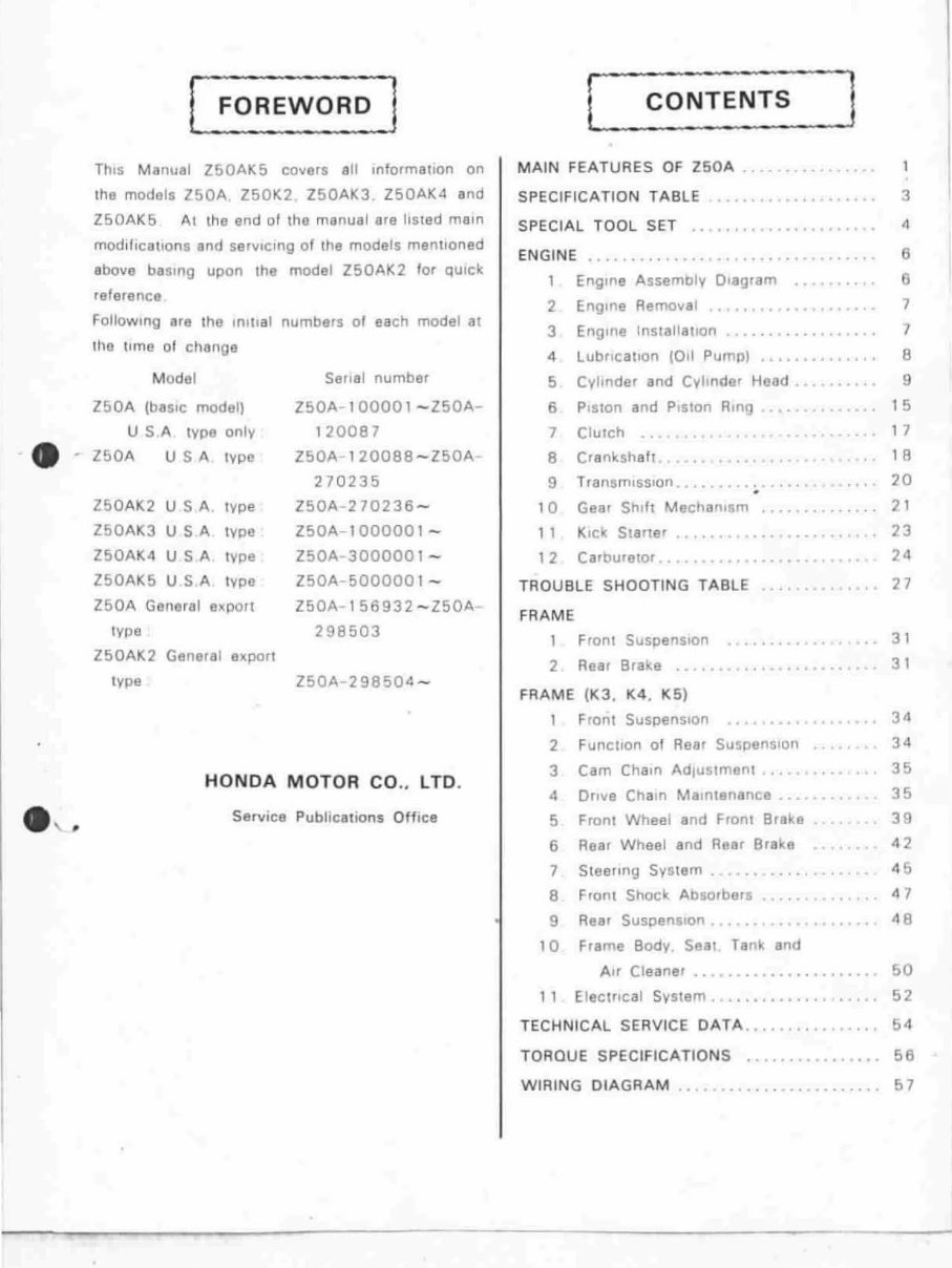
This Manual Z50AK5 covers all Information on
the models Z50A. Z50K2 . Z50AK3 . Z50AK4 and
Z50AK5 Al tho end of the manual are hSled main
modifications and servICing of the models mentioned
above baSing upon the model ZSOAK2 for qUick
reference
Following lire t ho Inlllal numbers of each model at
the time of change
M odel Serial number
ZSOA (baSIC model) Z50A- l 0000 I - Z50A-
USA tYpe only
_ - ZSOA USA I ype
Z50AK2 USA type
ZSOAK3 USA type
Z50AK4 USA type
Z50AK5 USA type
120087
l50A-l 20088 - l50A
270235
l50A 270236 -
Z50A -l 00000 1 -
Z50A - 3000001 -
l50A- 500000 1 -
Z50A General expol! Z50A-t 56932 - Z50A -
type 298503
Z50AK2 General expon
type l50' 298504 -
HONDA MOTOR CO .. LTD .
Service Publ ica t ions Office
MAIN FEATURES OF Z50A
SPECIFICATION TABLE
SPECIAL TOOL SET ..
ENGINE •• .... .. .....
1 Engine Assembly Diagram
2 Engine Removal
J Engine Inslallallon
4 lubrication 1011 Pump)
5 Cvllnder and Cvllnder Head .
6 PISlon and Piston Ring ...
7 ClUTCh
8
Crankshaft
9 TransmiSSion .
10 Gear Shift Mechanism .. ..
11 Kick Starter
1 2 Carbuletor .
TROU8LE SHOOTlNG TABLE ..
FRAME
Front Suspension
2 Rear Brake ..
FRAME (K3 , K4, K5)
1 Front Suspen s ion
2 FUnClIon 01 Rear Suspension
J Cam ChalO Adjustment
4 Dftve Chain Malntenence ...
5
Fronl Whee l and Front Brake
6
Rear Whoel and Rear Brake
7 Steeling System
8
Front Shock Absorbers
9 Real Suspension
10 Frame BodV Seal. Tank and
Air Cleaner . .
11 Electrical System
TECHNICAL SERVICE DATA .. .
TORQUE SPEC1FICATlONS ..
. .
3
6
6
7
7
8
9
15
1 7
1 A
20
21
23
24
27
31
31
34
34
35
35
39
42
4&
47
48
50
52
64
66
WIRING DIAGRAM .. . .. .... ........... 57
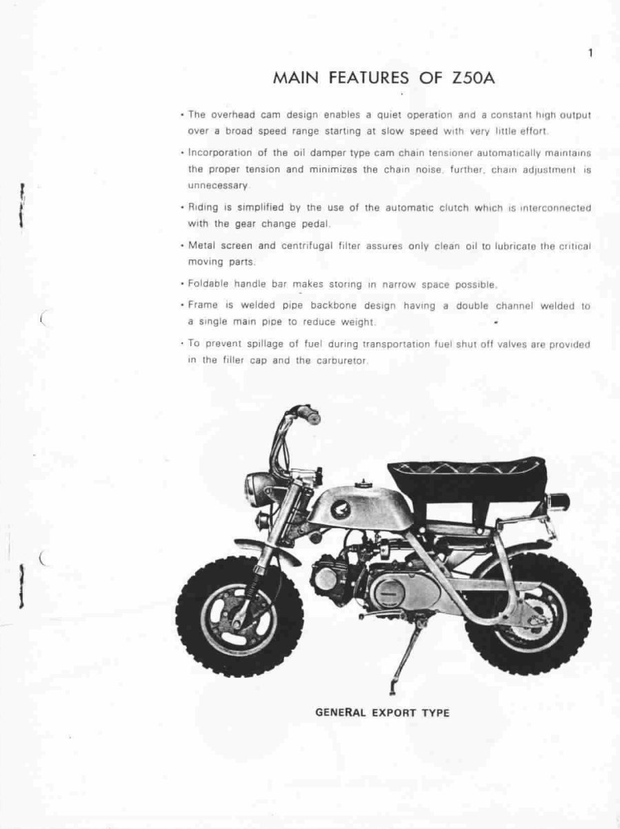
MAIN FEATURES OF Z50A
• The overhead cam design enables a qUIet operation and a constant tugh output
over a broad speed range starting at slow speed With very hHle eftOf!
· Incorooratlon of the 011 damper type cam chain tenslonar automallcally maintainS
the proper tenSion and min i miZeS the chain nOise funher . challl adjustmont 15
unnecessary
• Riding IS simplified by the use of the automatic clutch which IS Interconnected
with the gear change pedal
• Melal screen and centrifugal filter assures only clean 011 to lubricaTe the crilical
moving pans
• Foldable handle bar makes storing In narrow space poSSible
· Frame IS welded pipe backbone deSign haVing a double channel welded 10
a single main pipe 10 reduce weight
· To prellent spillage of fuel dUring transponal10n Iuel shul off votlo'es or provldeCJ
In the filler cap and lhe carouretor
GENERAL EXPORT TYPE
2
•
t
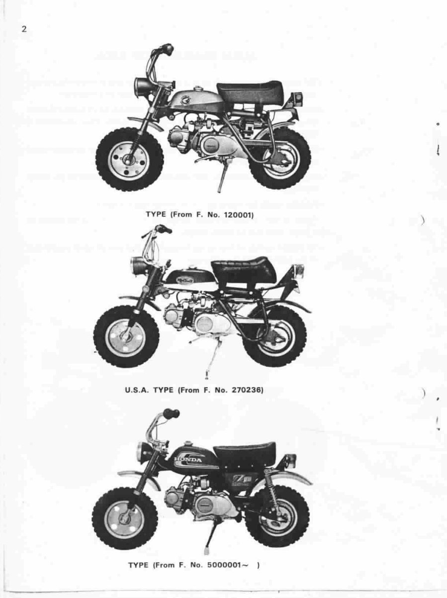
TYPE (F r om F. No . 120001)
)
I
•
U.S.A. TYPE (From F. No . 270236)
)
•
•
TYPE (From F. No. 5 000001 -
t
---- ----____ r-- --
•
,
3
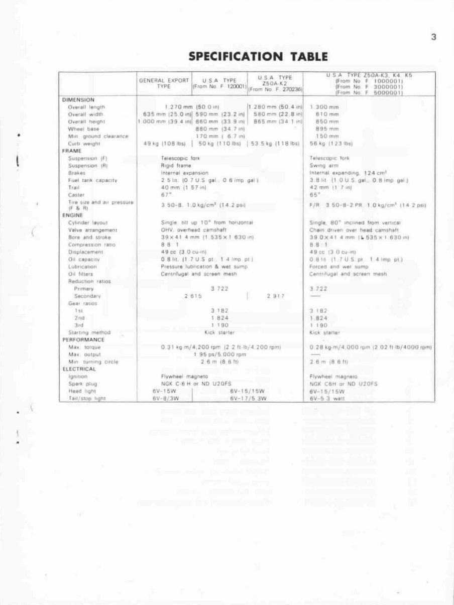
SPECIFICATION TABLE
.J
"
I USA p,- ,~vA': .. 1(4 III>
GEN(RAl£l(PO AT USA TYPE USA TYPE lJ-romNo F 1000001,
l50'" 1(2
TYPE !F.am NO f 120001 1111'1Om No F 7702311\ !~Iom No F 30000011
____________ r-____________ -L ______________ '-r ____________ -t ________ ""'"~.m~No .. _"_'S"O"O"O,O,O",'l
DIMENSION I
Ov ••• 11 I, .. ;". I 110 mm teo O,nl I' 180 mm (60 " ,m!
0 ..... '1 "",dill 1135mm 125 0'"11 590m'" 12311111 580mm (22 8,"1
0" •• ,11 ""11"\ 1 000 mm 139 • In! 8110 mm 133 9 "Ii IllS "'m 134 1 .nl
Wt\ft l b," 880 ,.,," 134 1 tnl
M,n 9'OUnJJ (1"" 1>0;'
C.. ,b _'11'11
"'MAM[
SlIsptllJlU1I 1Ft
.suJj)<oIn,l('Jn IAI
8r.ln
F"~I ,. "_ (,'U '''''V
h •• 1
C.<I.,
1". 1.,..1>11 'd g',n., ••
I" & At
[NGINf:
Cyl.fICM, "\'0'"
Y.I~I .1I'I\9.m'I'\I
80" .. na 11' ......
Como,,,,,on '.100
OIIIlI.c, ..... "'1
all C'PICII\I
l"1I.oe;.1I0,,
0,1 "h.,.
R.II",IIOII "IIC1a
Pllm •• '1
'iIKQtlo.l.,.
G", '.,_
,,,
2..d
].,
51""11\1 1'IIe11>Od
P[RF ORM"'NCE
Nih IOhWot
M I< QUlaul
M," lUI"'"" ~jtet.
(LECTl'ltC",L
Ign'hon
Sp,H plug
Ilud ,gilt
r ", '&Wfo I'ont
170m", t 157'1'1
"!I_IIP0811l" I 50~g/l101hl 5l5~1I1118Ibl'
T,I~c IQ"
RIIiI'd h.m •
Int,,",1 "1l11l11On
25 10 1 ,01U511' 081mllllill
.. 0 "'''' II 57 '1'1
".
lSO-8 I 04licm
'
l'oI lpt'l
s""V" nl! UOII 10· ltom "Do'lon .. )
OH.... 0.., .... 0 elm.n".,
391'<"1 ""' ... II 5]5.' 11]0-111
.. ,
"9ee II Oeu'lIl
081', 111US 01 , .. Imo PI
PI"'"", luDnelllorl 6 WI' .",mll
C''''''''''9.1 .1\0 .e,un ",un
3722
1 182
I 824
1 190
(,e ' "'''"'
2 91 ,
031'11"'1"·200,,,", 12 2 II ,0,4 ZOOroml
I 95 ~f5 000 ,om
115m 18 1'1'11
fl~ ...... " 1 ""gl\lIO
NGII: C 8 H or ND U20FS
15V-15W 1 15V-IS,ISW
8V-8.3W I W-l1iS JW
I ]00 mm
810",,,,
860",",
8C)'i "''''
150 r1'm
58
1
0111l
'
bll
f,I'~IlI>C ",.j
Sw'"g I,m
InlilOUtl ,.p,"lI'"g 121 c... '
3B.,\ (I OUS gl' 081rng 1iI.11
12""n """1
.S·
~ R 1 SO. 2PR I Q'!1{Cm' ,tl 2'""1
S""u" 80 'fIC-J.~ 110ft' "",,.ell
Ch"" " ••• ,,- ·h.' I'ttld c.,m,hlll
390XII<II ... ", ~ &J5'-1810,nl
.. ,
19 te I) ac", In,
o 8'" f1 . U S P' 1" ''''JI 1111
!'n'e," 'I'" w" I"'mo
C ... ".I"'III' ,"a -K'I'" _tn
] n.Z
1 18]
1824
, 190
11;. _. 'l.fI.,
078 _II ....... 000 111m 12 02 /Ilb / .OOO .pml
Z 8 m ,ft 8111
fl't'W,,"' '"1Q"'tO
!\oCf Clltt lJI NO U20rS
8V I !Ill SW
6V·!t'l .... "1
4
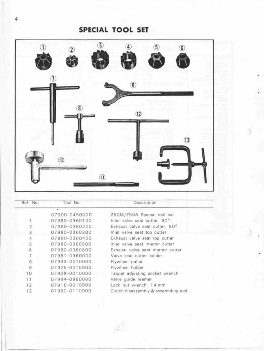
SPECIAL TOOL SET
®
®
®
\
1
=
,
Ref No Tool No Description
07900 0450000 Z50M / Z50A Special tool sel
07980-036010 0 Inlel valve seal cutler, 90·
2 07980-0360200 Elthaust valve seat cutter. 90·
3 07980-0360300 Inlet valve seal lOp cutler
)
4 07980 -0360 400 Exhaust valve seat top cutlsr
5 07980 -0360500 Inlel valve seal Inienor cuner
6 07980-0360600 e.haust valve seal I'lienor cunar
7 07981-0360000 Valve seal cutler holder
•
8 07933-0010000 Flvwheel puller
9 079250010000 Flywheel holder
10 07908 -0010 000 TaDpel adjusting socket wrench
1 1 07984 -09 80000 Valve gUide reamer
1 2 07916 -00 10000 lock nUl wrench. 1 4 mm
1 3 07960 -01 10000 Clutch d is assembly & assembling 1001
-
5
•
,
.
-- --
- -~- ~ ..
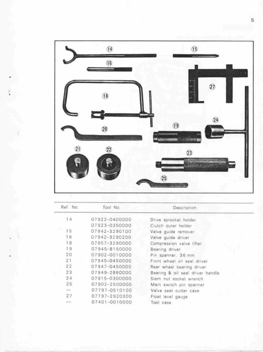
Ref No Tool No Description
14 07922-0400000 Dnve sprocket holder
07923-0360000 Clutch outer holder
1 5 07942-3290100 Valve gUide remOver
16 07942-3290200 Valve gU i de driver
18 07957-3290000 Compress i on va lve hfter
19 07945-8150000 Bearing driver
20 07902-0010000 Pin spanner . 36 mm
21 07945-0450000 Front wheel a ll seat driver
22 07947-0450000 Rear wheel bearing dr iver
23 07949 - 2860000 Bearing & 011 seal driver handle
24 07915 - 0300000 Stem nUl socket wrench
25 07902 -2 500000 MaIO sWllch pin spanner
07797 - 0510100 Valve seRt culter case
27 07797 - 2920300 Float 18 ... el gauge
07401 - 0010000 Toot case
6
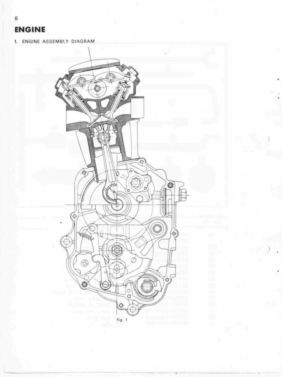
ENGINE
1. ENGINE ASSEMBLY DIAGRAM
---
Fig 1
•
)
- - ,
•
•
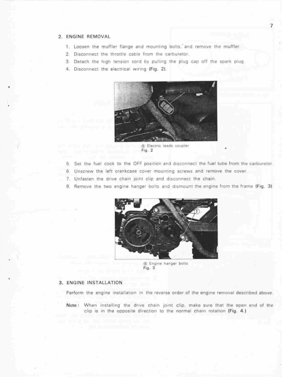
2. ENGINE REMOVAL
1 loosen the muffler flange and mounting bolts : and remove the muffler
2 Disconnect the throttle cable from the carburetor
3 Detach the high tension cord by pulling the plug cap off the spark plug
4. Disconnect the electrrcal wlnng (F ig. 2)
Eleelnc l«Iad S coupler
Fig . 2
7
5 Set the fuel cock 10 the OFF poSition and disconnect the fuel l ube from rha carburetor
6 Unscrew the leh crankcase cover mounting screws and remove the cover
7 Unfasten the orlve chain JOlnl clIp and disconnect the chetn .
a Remove the two engine hanger bolts and dismount the engme from the Irame (FlO 31
3. ENGINE INSTALLATION
(J) EnQIf'18 nange, bolts
Fig . 3
Perform the engine Installallon In the reverse order of the engln8 remoyal deSCribed above
Noto : When installing the drille chain JOint clip. make sure that the opon ond 01 lhe
cliP IS m the opposite direction to tt,e normal chain rolation (Fi g .4 I
B
Dll ection 01 R otall<W1
-
~--~
J -2, ( - - -
m O .4- 0.8in)
FIg . 4 ChaIn jomt chp InliaHauon
Fi g. 5 Englntl 011 10ull'lS
<D 011 punlp Issol"lbly
Fig . 6
)
4 . LUBRICATION lOlL PUMP)
A. Desc ription
The engine oil which has been picked up
by the trochoid p ump 16 diverted InlO TwO
routes (Fig . 51 .
Route one
all IS. sent through the nght cran kcase
- uQht crankcase cover - centrl 'ugal
filter - connecting rod large end rollers
Route two
0.1 IS sent through Ihe cylinder sTud boh
- rock.er arm Side cover ca mshaft
profiles and oeanngs - valve mechanism
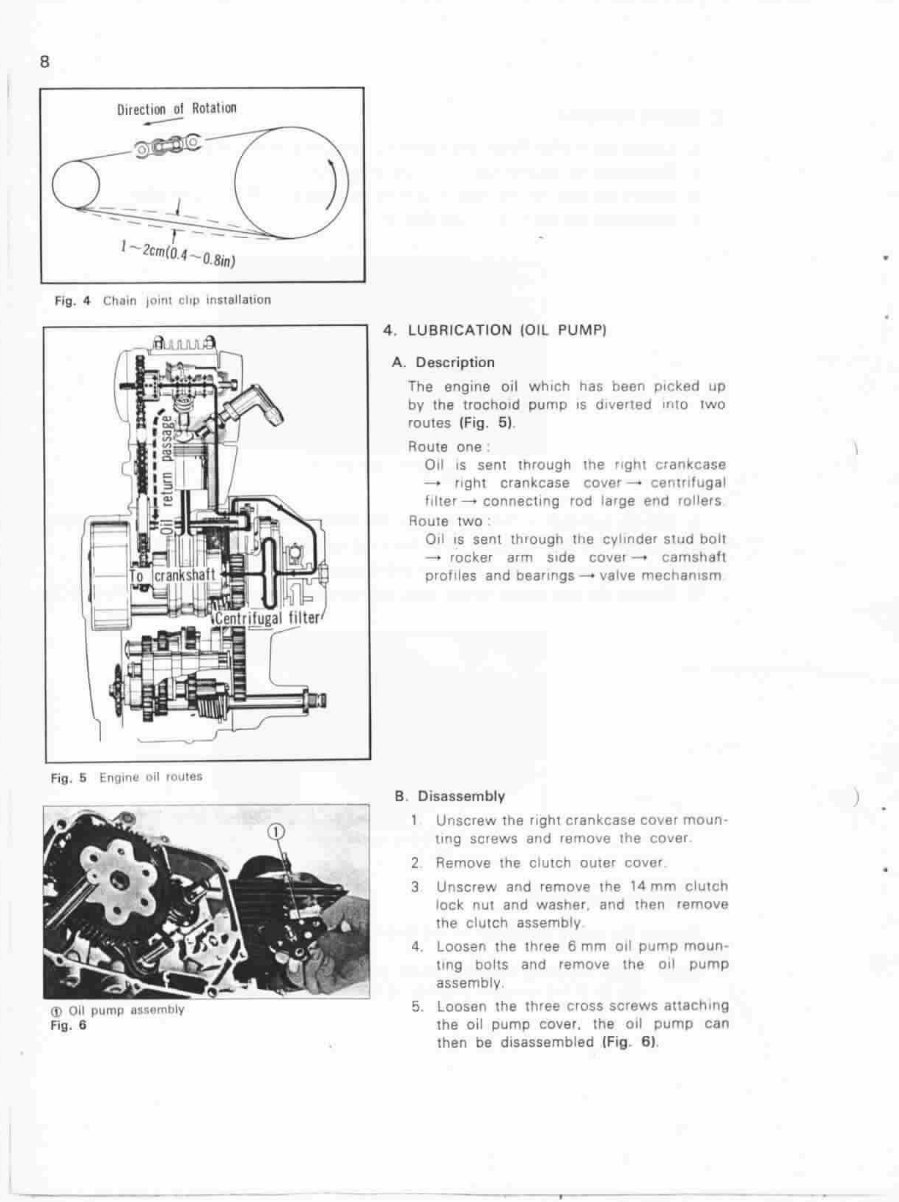
B. Disassembly
1 Unscrew the light crankcase covel moun·
ung screws and remove the COveT
2 Remove the clutch DUler cover
3 Unscrew and remalle the 14 mm clutch
lock nUl and washer, and then 'emove
the clutch assembly
4, Loosen the three 6 mm 011 pump moun·
tlng bolts and remove the 011 pump
assemblv
5. loosen the three ClOSS scre ..... s attaching
the all pump cover, the oil pump can
then be disassembled IFig . 6) ,
•
You're Reading a Preview
What's Included?
Fast Download Speeds
Online & Offline Access
Access PDF Contents & Bookmarks
Full Search Facility
Print one or all pages of your manual
$30.99
Viewed 87 Times Today


Secure transaction
What's Included?
Fast Download Speeds
Online & Offline Access
Access PDF Contents & Bookmarks
Full Search Facility
Print one or all pages of your manual
$30.99
This manual provides comprehensive coverage of the Z50A, Z50K2, Z50K3, Z50K4, and Z50K5 models, offering essential information for car repair enthusiasts and professional mechanics alike.


