OJ GENERAL INFORMATION GENERAL SAFETY SERVICE RULES MODEL IDENTIFI CAT ION SPECIFICATIONS GENERAL SAFETY , II , -, , -, ' -2 ' -3 If, hr rngin, mllst be r"""ing to do some .... ork, make slIn ' Ir e (I na is "'ell·~"t;laud. Never ru n tir e engine in an encloud a na. Tire exlraust contains poisonous carbon monoxide gas tlltl! ell" CIHI5e loss ofconsciousnns and may lead todeat h. Inhaled asbestos Jibers hQI'I! been found to cause rupiratory disease and concer. Never use an air hose or dry brush 10 clean breake or clutch as- sembliu. SERVICE RULES TORQUE VALUES TOOLS CAB LE & HARNESS ROUTING ' -5 ' -7 ' -9 Gasoline is ex t nmdy j1llmmable (llld is uplosire " nder u- rtoi" conditions. Do not smoke or allow flamu or sparks in the "'Ork ana or "'he" gasoline is stored. • Use genuine HONDA or HONDA-recommended parts and lubricants or their equivalents. Parts that do not meet HONDA 's design specifications may damage the motorcycle . • Use the special tools designed for this product . • Install new gaskets , O-rings, cotter pins. lock plates, etc. when reassembling. • When torquing a series of bolts or nuts , begin with the larger-diameter or inner bolts first, and tighten to the specified torque diagonally, unless a particular sequence is specified. • Clean parts in non -flammable or high flash point solvent upon disassembly. lubricate any sliding surfaces before re- assembly. • After reassembly, check all parts for proper installation and operation. • Use only metric tools when servicing this motorcycle. Metric bolts, nuts. and screws are not inte rchangeable with English fasteners. The use of incorrect tools and fa$teners may damage the motorcycle. • Route all electrical wires as shown on pages 1-9 through 1-12, Cable and Harness Routing, and away from sharp edges and areas where they might be pinched between moving parts. 1-1
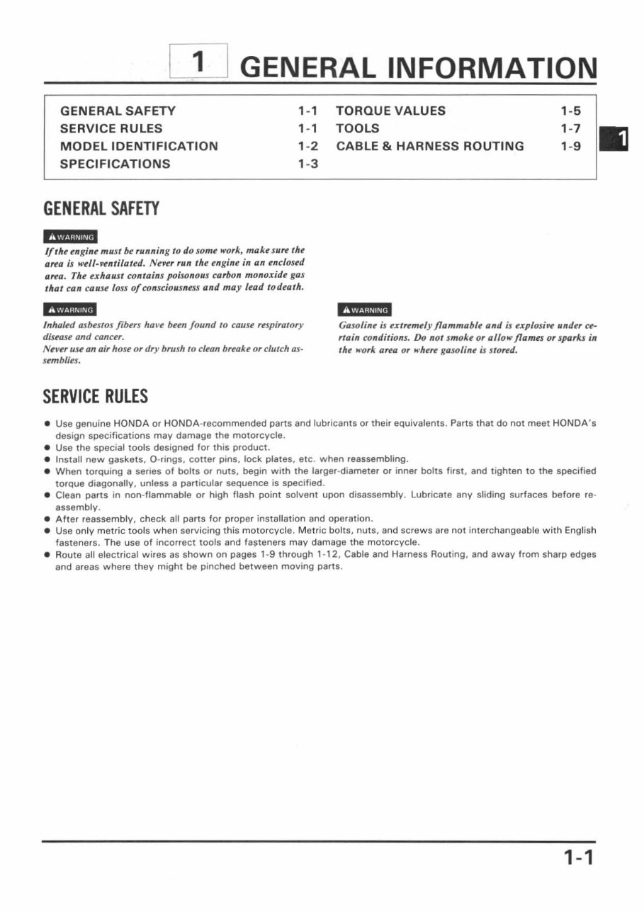
GENERAL INFORMATION MODEl IDENTIFICATION The engine serial number is stamped on the lower left side of the crankcase. The ca rburetor identifi cation number is on the right side of the carbu r etor body. 1-2 The frame serial number is stamped on the right side of the steering head. The color code label is attached to the left frame tube under the seat. When ordering a color coded part, always specify its designated color code.
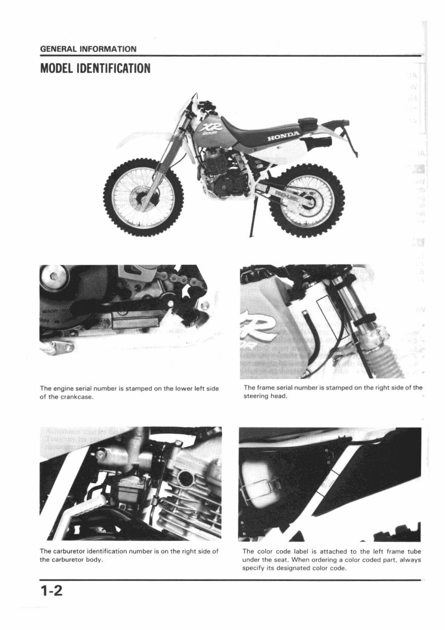
GENERAL INFORMATION SPECIFICATIONS ITEM SPECIFICATION DIMENSIONS Overall length 2,160 mm (85.0 in) Overall width 900 mm (35 .5 in) (8 model) 980 mm (35 .4 in) (U model) Overall height 1.210 mm (48 .0 in) (8 model ) 1,220 mm (48 .0 in) (U model) Ground clearance 335 mm ( 13 .2 in) Wheelbase 1,460 mm ( 57 .5 in ) (8 model) 1,455 mm (57 .3 in) (U model) Seat height 940 mm (37.0 in) Foot peg height 418 mm (16 .5 in) (l) / 420 mm (16 .5 in) (R) Dry weight / Curb weight 120.5 kg (26 . 5Ib)/ 130. 5kg 1 287 .S Jb) FRAME Type Semi double cradle Front suspension. travel Telescopic 280 mm 11 ' .0 in) Rear suspension, travel Pro-link 280 mm ( 11 .0 in) Tire size (8 model) (U model ) Front 80/ 100- 215IM 3. 00 - 21-4PR Rear '10/ 10Q- 1864M 4.50 - 18- 4PR Tire pressure Front 15 Psi ( 1 00 kpa, 1.0 kg /cm 2 ) Rear 15 Psi ( 1 00 kpa, 1.0 kg/ cm 2 ) Front brake , swept area Disc, dual piston caliper Rear brake, swept area Drum , leading/ trailing shoes Fuel capacity 10 .0 l it (2 .7 U.S. gal. 2.3 Imp gal) Fuel reserve capacity 2.0 lit (0.5 U.S. gal. 0.4 Imp gal) Caster 62' Trail 118 mm (4 .6 in) Front fork oil capacity 643 cc (2 1.8 oz) ENGINE Type Gasoline, air -cooled 4-stroke SOHC Cylinder arrangement Single cylinder inclined 15" Bore and stroke 97 x 80mm(3 .B2 x 3. 15in) Displacement 591 cc (36 .1 cu in) Compression ratio 9. 0: 1 Valve train 4-valve, single chain driven SOHC, RFVC Oil capacity 2.31it (2.4 U.S. qt, 2.0 Imp qt) Lubrication system Forced pressure and dry sump Air filtration system Oiled polyurethane foam Cylinder compression 500 ± 100 kPa (5 ± 1 kg/ cm 2, 71 .1 ± 14 .2 psi) De- compressor effected Intake valve Opens 5" (BTCD) at 1 mm lift Closes 40" (ABDC) at 1 mm lift E)(haust valve Opens 45 " (BBD C) at 1 mm lift Closes 5" (ATDC) at 1 mm lift Valve clearance Intake 0. 10 mm (0 . 004 in) E)(haust 0. 12 mm (0 . 005 in) CARBURETOR Type Piston valve 1.0 . number PD8AA Main jet ;I: 165 (B model), ;I: 135 (U model) Pilot screw 2-5/ 8 turns out Float level 14.5 mm (0.57 in) Idle speed 1, 300 ± 100 min · 1 (rpm ) 1-3
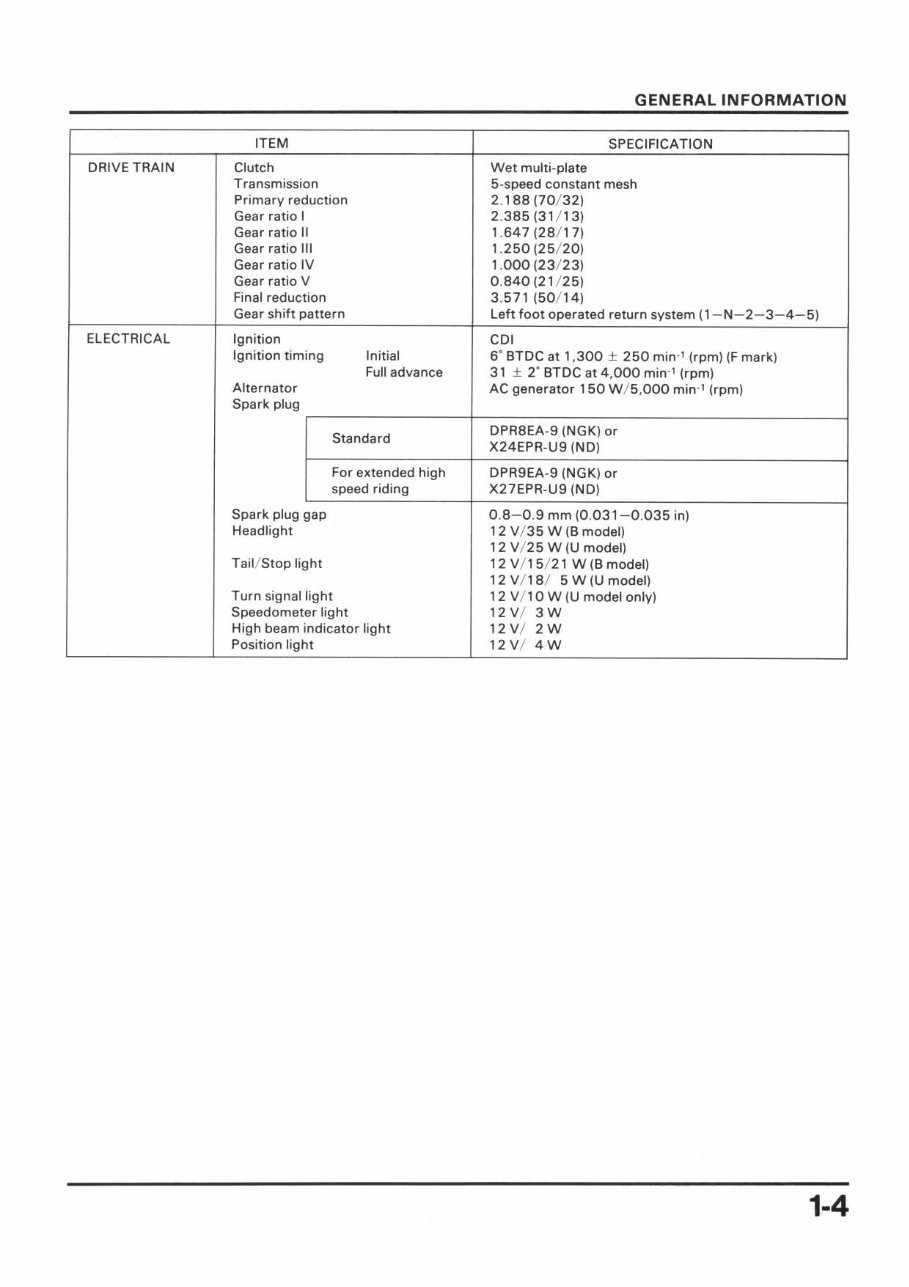
GENERAL INFORMATION ITEM SPECI FI CATION DRIVE TRAIN Clutch Wet multi -plate Transmission 5-speed constant mesh Primary reduction 2. 188 (70 / 32) Gear ratio I 2.385(31 / 13) Gear ratio II 1.647 (28/1 7) Gear ratio III 1. 250 (25/20) Gear ratio IV 1.000 (23 / 23) Gear ratio V 0. 840 (21 / 25) Final redu ction 3.571 ( 50/ 14) Gear shift pattern Left foot operated return system (1-N-2-3-4-5) ELECTRICAL Ignition CDI Ig nition tim ing Initial 6' BTDC at 1, 300 ± 250 min -' (rpm) (F mark) Full advance 31 ± 2' BTDC at 4,000 min " (rpm) Alternator AC generator 150 W / S,OOO min " (rpm) Spark plug Standard DPR8EA-9 (NGK) or X24EPR- U9 (ND) For extended high DPR9EA-9 (NGK) or speed riding X27EPR- U9 (NO) Spark plug gap 0.8- 0.9 mm (0.031-0.035 in) Headlight 12 V/ 35 W (8 model) 12 V/ 25 W (U model) Tai l/ Stop light 12 V/ 15/ 21 W (8 model) 12V/ 18/ 5W(U model ) Turn signal light 12 V/ 1 0 W (U model only) Speedometer light 12 V/ 3 W High beam indicator light 12 V/ 2 W Position light 12 VI 4W 1-4
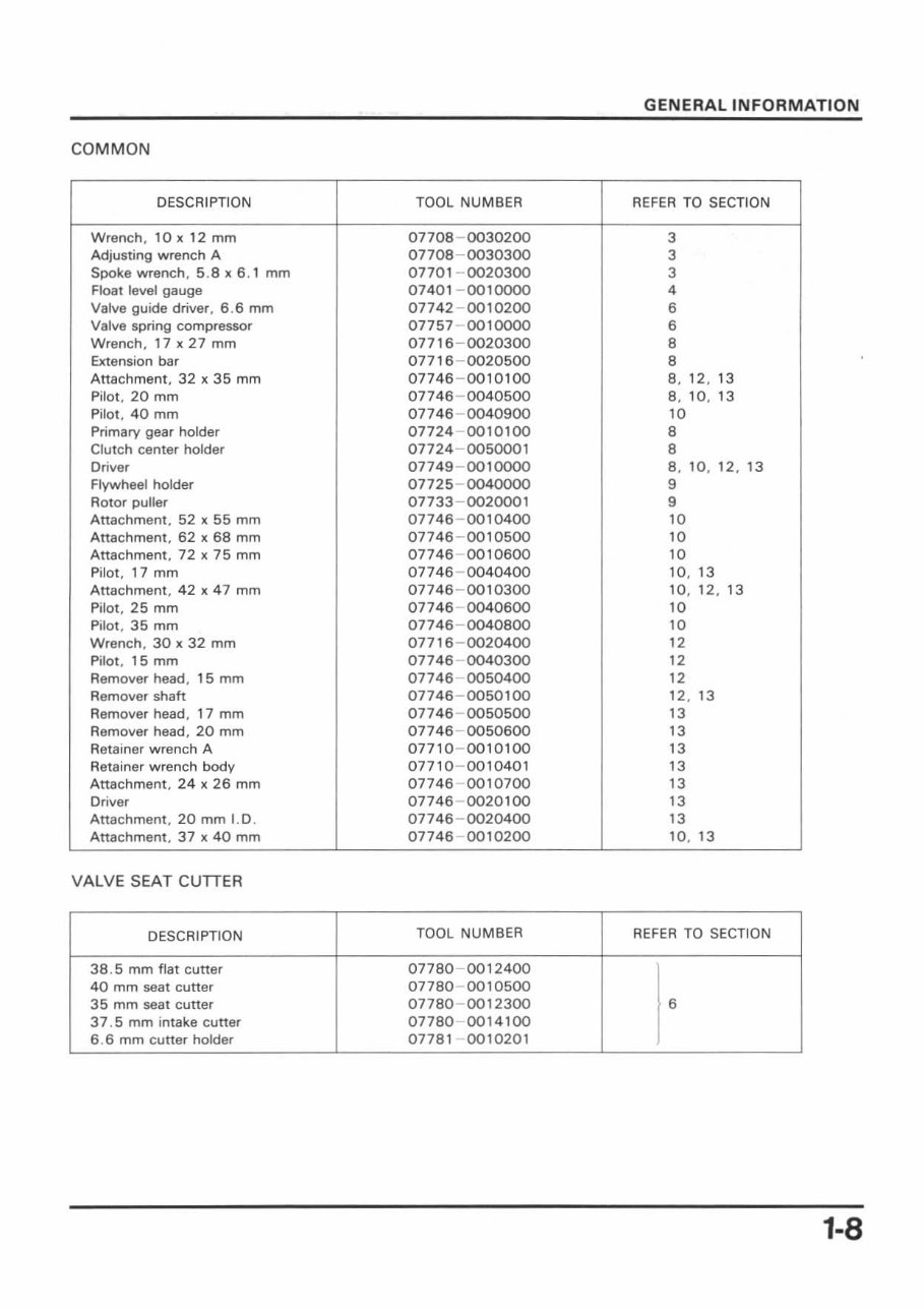
COMMON DESCRIPTION Wrench, 10 x 12 mm Adjusting wrench A Spoke wrench , 5.8 x 6.1 mm Float level gauge Valve guide driver , 6 .6 mm Valve spring compressor Wrench, 17 x 27 mm Extension bar Attachment, 32 x 35 mm Pilot, 20 mm Pilot, 40 mm Primary gear holder Clutch center holder Driver Flywheel holder Rotor puller Attachment , 52 x 55 mm Attachment, 62 x 68 mm Attachment, 72 x 75 mm Pilot, 17 mm Attachment, 42 x 47 mm Pilot , 25 mm Pilot, 35 mm Wrench , 30 x 32 mm Pilot , 15 mm Remover head, 1 5 mm Remover shah Remover head, 1 7 mm Remover head. 20 mm Retainer wrench A Retainer wrench body Attachment, 24 x 26 mm Driver Attachment , 20 mm I.D . Attachment , 37 x 40 mm VALVE SEAT CUTTER DESCRIPTION 38 .5 mm flat cutter 40 mm seat cutter 35 mm seat cutter 37 .5 mm intake cutter 6 .6 mm cutter holder TOOL NUMBER 07708 - 0030200 07708 - 0030300 07701 - 0020300 07401 - 0010000 07742 - 0010200 07757 - 0010000 07716 - 0020300 07716 - 0020500 07746 - 0010100 07746 - 0040500 07746 - 0040900 07724 0010100 07724 - 0050001 07749 - 0010000 07725 - 0040000 07733 - 0020001 07746 - 0010400 07746 - 0010500 07746 0010600 07746 - 0040400 07746 - 0010300 07746 - 0040600 07746 - 0040800 07716 - 0020400 07746 - 0040300 07746 - 0050400 07746 - 0050100 07746 - 0050500 07746 - 0050600 07710 - 00 10100 07710 - 0010401 07746 0010700 07746 - 0020100 07746 - 0020400 07746 - 0010200 TOOL NUM8ER 07780 - 0012400 07780 0010500 07780 - 0012300 07780 - 0014100 07781 0010201 GENERAL INFORMATION REFER TO SECTION 3 3 3 4 6 6 8 8 8, 12 , 13 8, 10,13 10 8 8 8, 10 , 12 , 13 9 9 10 10 10 10, 13 10, 12, 13 10 10 12 12 12 12 , 13 13 13 13 13 13 13 13 10 , 13 REFER TO SECTION I 6 1-8
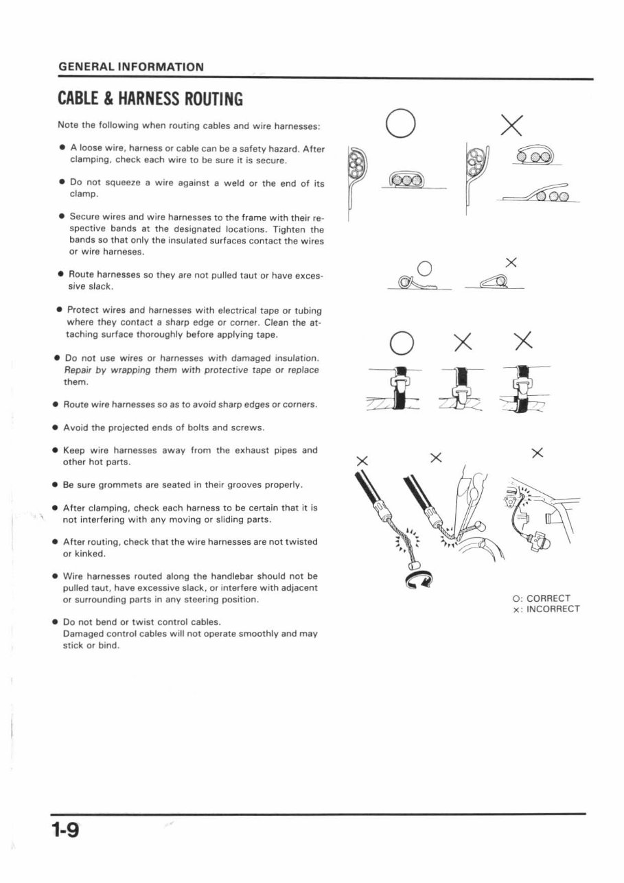
GENERAL INFORMATION CABLE & HARNESS ROUTING Note the following when routing cables and wire harnesses: • A loose wire , harness or cable can be a safety hazard. Ahar clamping , check each wire to be sure it is secure. • Do not squeeze 8 wire against a weld or the end of its clamp . • Secure wires and wire harnesses to the frame with their re- spective bands 8t the designated locations. Tighten the bands so that only the insulated surfaces contact the wires or wife harneses. • Route harnesses so they Bre not pulled taut or have exces- sive slack. • Protect wires and harnesses with electrical tape or tubing where they contact a sharp edge or corner. Clean the at- taching surface thoroughly before applying tape. • Do not use wires or harnesses with damaged insulation. Repair by wrapping them with protective tape or replace them. • Route wire harnesses so as to avoid sharp edges or corners. • Avoid the projected ends of bolts and screws . • Keep wire harnesses away from the exhaust pipes and other hot parts . • Be sure grommets are seated in their grooves properly. • After clamping. check each harness to be certain that it is not interfering with any moving or sliding parts. • After routing. check that the wire harnesses are not twisted or kinked. • Wire harnesses routed along the handlebar should not be pulled taut , have excessive slack, or interfere with adjacent or surrounding parts in any steering position . • Do not bend or twist control cables. Damaged control cables will not operate smoothly and may sti ck or bind. 1-9 o x x x ~ x 0: CORRECT x: INCORRECT
Our service repair workshop manual is a comprehensive guide supplied in an easy-to-read format, covering all repairs from A-Z and all models. It is a valuable resource for both professional mechanics and DIY enthusiasts.
The manual covers major repair topics in great detail and includes high-quality pictures and diagrams for easy understanding. It encompasses maintenance and servicing, engine and clutch, transmissions, cooling systems, fuel and exhaust, ignition and electrical, brakes and brake assembly, wheels and tires, steering and suspension, frame and bodywork, wiring diagrams, fault finding troubleshooting, and much more.
Compatible with all operating systems, including PC and MAC, such as Windows 95, 98, 2000, Me, Xp, Vista, and Windows 7, this manual is a professional-quality source of information that can be accessed instantly without any waiting time.