

1991-1996 XR250L Service & Repair Manual
What's Included?
Fast Download Speeds
Online & Offline Access
Access PDF Contents & Bookmarks
Full Search Facility
Print one or all pages of your manual
L-~
--
- -~~
91·96
XR250L
•
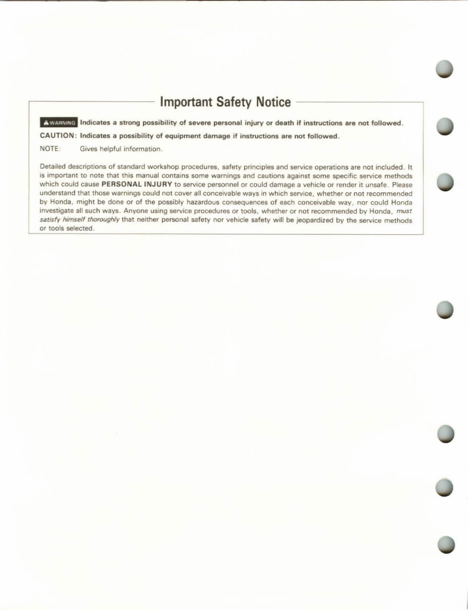
Important Safety Notice
Indicates a stlOng possibi li ty of severe personal injury Of death if instructions are no t followed .
CAUTION : Indicates a possibility of equ i pment damage if instructions 8re not followed .
NOTE Gives helpful information .
Detailed descriptIons of standard workshop procedures. safety principles and saNiee operations are not included. It
is important to note that this manual contains some warnings and cautions against some specific service methods
which could cause PEASONAllNJURY to service personnel or could damage a vehicle or re nder it unsafe Please
understand that those warnings could not cover all conceivable ways In which service, whether or not recommended
by Honda, might be done or of the possibly hazardous consequences of each conceivable way , nor could Honda
investigate aU such ways . Anyone using service procedures or tools, whether or not recommended by Honda, must
slJtlsly himself thoroughly that neither personal safety no r vehicle safety will be jeopardized by the service methods
or tools selected .
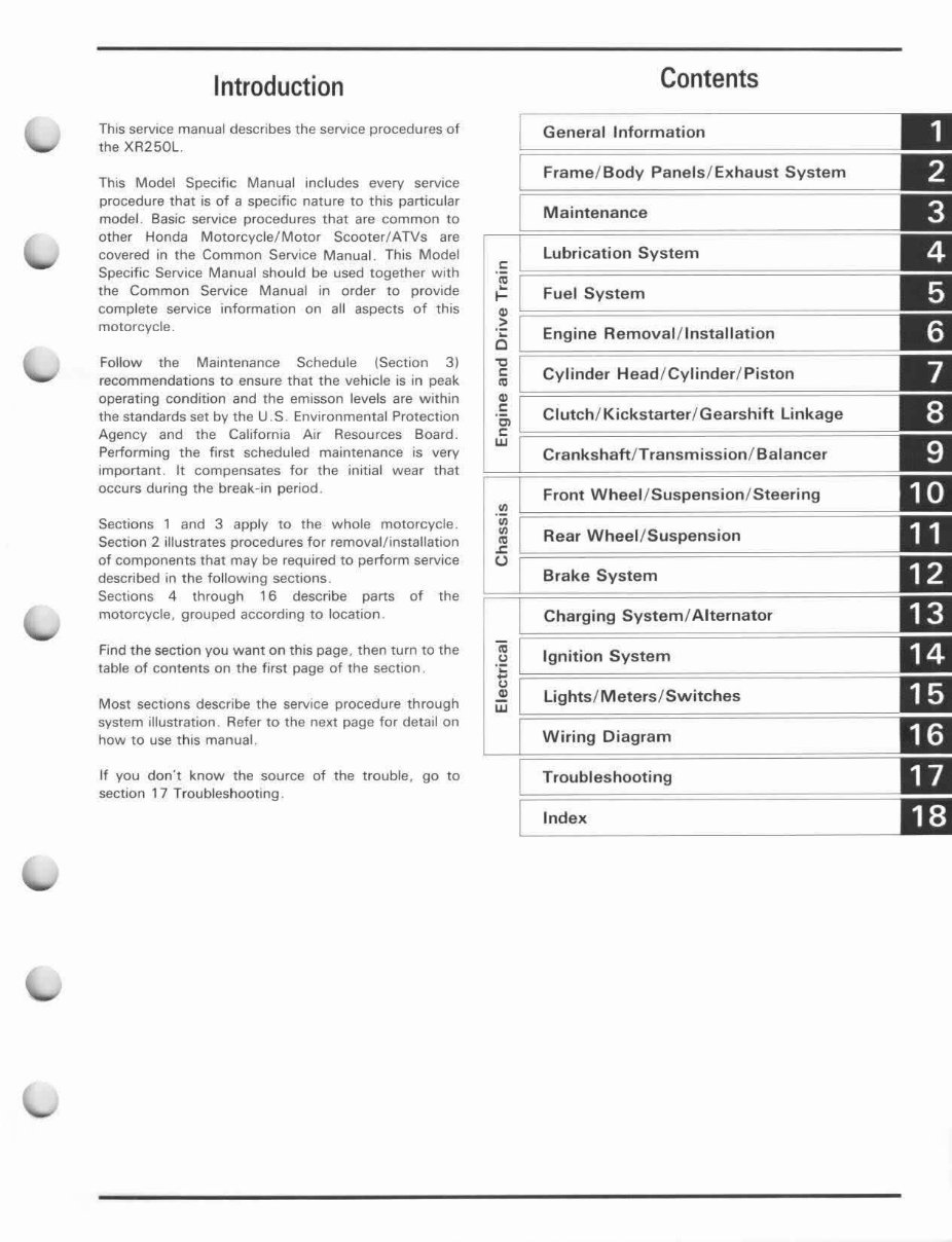
Introduction
This service manual describes the service procedures of
the XR250L.
This Model Specific Manual includes every service
procedure that is of a specific nature to this particular
model. Basic service procedures that are common to
other Honda Motorcycle/Motor Scooter/ATVs are
covered in the Common Service Manual. This Model
Specific Service Manual should be used together With
the Common Service Ma nual in order to provide
comp lete service information on all aspects of this
motorcycle.
Follow the Maintenance Schedule (Section 3)
recommendations to ensure that the vehicle is in peak
operating condition and the emisson levels are Within
the standards set by the U.S. Environmental Protection
Agency and the California Air Resources Board.
Perfo rming the first scheduled maintenance is very
Important . It compensates for the initial wea r that
occurs du ring the break-in period.
Sections 1 and 3 apply to the whole motorcycle.
Section 2 illustrates procedures for removal/ installation
of components that may be required to perform service
described in the following sections .
Sections 4 through 16 describe parts of the
motorcycle, grouped according to location .
Find the section you want on thiS page, then turn to the
table of contents on the first page of the section .
Most sections describe the service procedure through
system illustration. Refer to the next page f or det ail on
how to use t h iS manual.
If you don "t know the source of the trouble , go to
section 17 Tr ou b leshooti ng .
o
•
.::
~
."
o
"tl
o
•
~
Contents
General Information
Frame / Body Panels/ Ex haust Sy stem
Mainten a nce
Lubrica tion Sy ste m
Fuel System
Engine Remova l/In stal l ation
Cy lind er Head/ Cylinder / Pi ston
c: Clutch / Kickstarter / Gearshift Linkage
Jf ~=====================================
Crankshaft / Transmi ss ion / Balan ce r
Front Wheel / Suspension / Steering
Rear Wheel / Suspension
Brake System
Charging System / Altern ator
Ignition System
Light s/ Meters / Switches
Wiring Di agram
Trouble s hooting
Ind ex
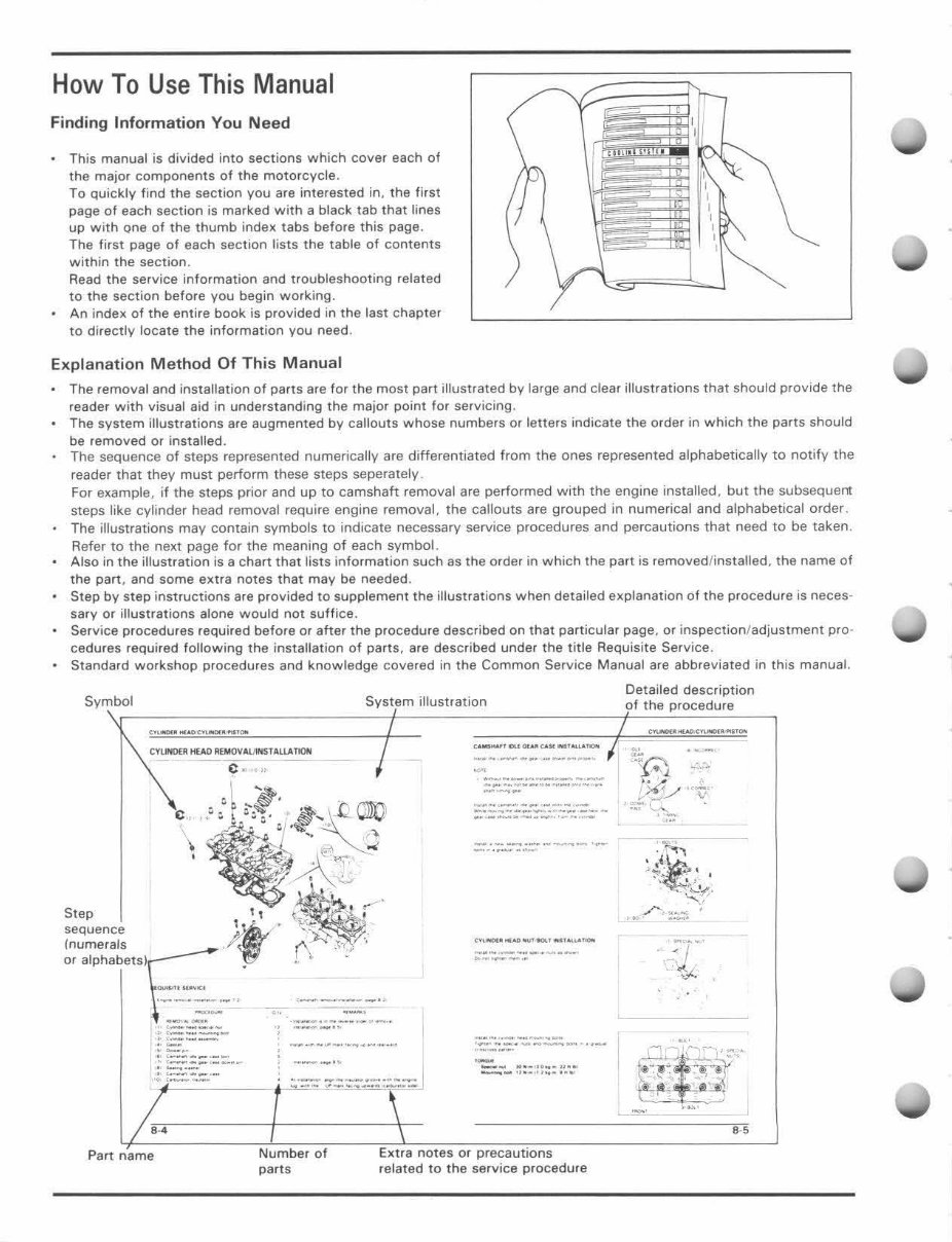
How To Use This Manual
Finding Informati on You Ne ed
This manual is divided into sections which cove r each of
the major components of the moto rcycle.
To quickly find the section you are inte rested in, the fir st
page of each section is marked with a black tab that lines
up with one of the thumb index tabs before this page.
The first page of each section lists the table of contents
within the section.
Read the service information and troubleshooting related
to the section before you begin working.
An index of the entire book is provided in the last chapter
to directly locate the info rmat ion you need.
Explanation M ethod Of This Manual
The removal and installation of parts are for the most part illustrated by large and clear illustrations that should provide the
reader with visual aid in understanding the major point for servicing.
The system illustrations are augmented by caliouts whose numbers or letters indicate the order in which the parts should
be removed or installed.
The sequence of steps represented numerically are differentiated from the ones represented alphabetically to notify the
reader that they must perform these steps seperately .
For example. if the steps prior and up to camshaft removal are performed with the engine installed, but the subsequent
steps like cylinder head removal require engine removal, the callouts are grouped in numerical and alphabetical order .
The illustrations may contain symbols to indicate necessary service procedures and percautions that need to be taken .
Refer to the next page for the meaning of each symbol.
Also in the illustration is a chart that lists information such as the order in which the part is removed/installed, the name of
the part, and some extra notes that may be needed.
Step by step instructions are provided to supplement the illustrations when detailed explanation of the procedure is neces-
sary or illustrations alone would not suffice.
Service procedures required before or after the procedure described on that particular page, or inspection / adjustment pro-
cedures required following the installation of parts, are described under the title Requisite Service.
Standard workshop procedures and knowledge covered in the Common Service Manual are abbreviated in this manual.
Symbol
,
System illustration
1\~~~~V~~TAlUOON -- I
1\ ' ~,
\ f:'A ...
-~~
Step
. " ~ ~ . '.' "- /
sequence ~J.j' ~
't" "'"
(numerals /' ,C . r\ ,. .~-'_~"
0' "Ph'bm'r;;_ , __ ____ "
~ ~=~:~
::::' .... -":'- ., ::=~,,:,~._._ -_.
'~ ~::: :::: =-
,-
" - .
. , '-- -< --
; :=::::.- -_ .. -
::~=":.!:.. -
/
/ e-,
----"
--------.-
____ M_'·M __ ~"_ .. _
--...~.
-.--~----~-'- _",_A_
--.----.---
.. _---
-- -,---~-
,- - -. --~-- .. -
-- .... .... -".~
--.- " .~ .. , ~- , ...
Part name
Number of
parts
Extra notes or precautions
related to the service procedure
Detailed description
of the procedure
c~ .... ",c ......... " ,.
e,
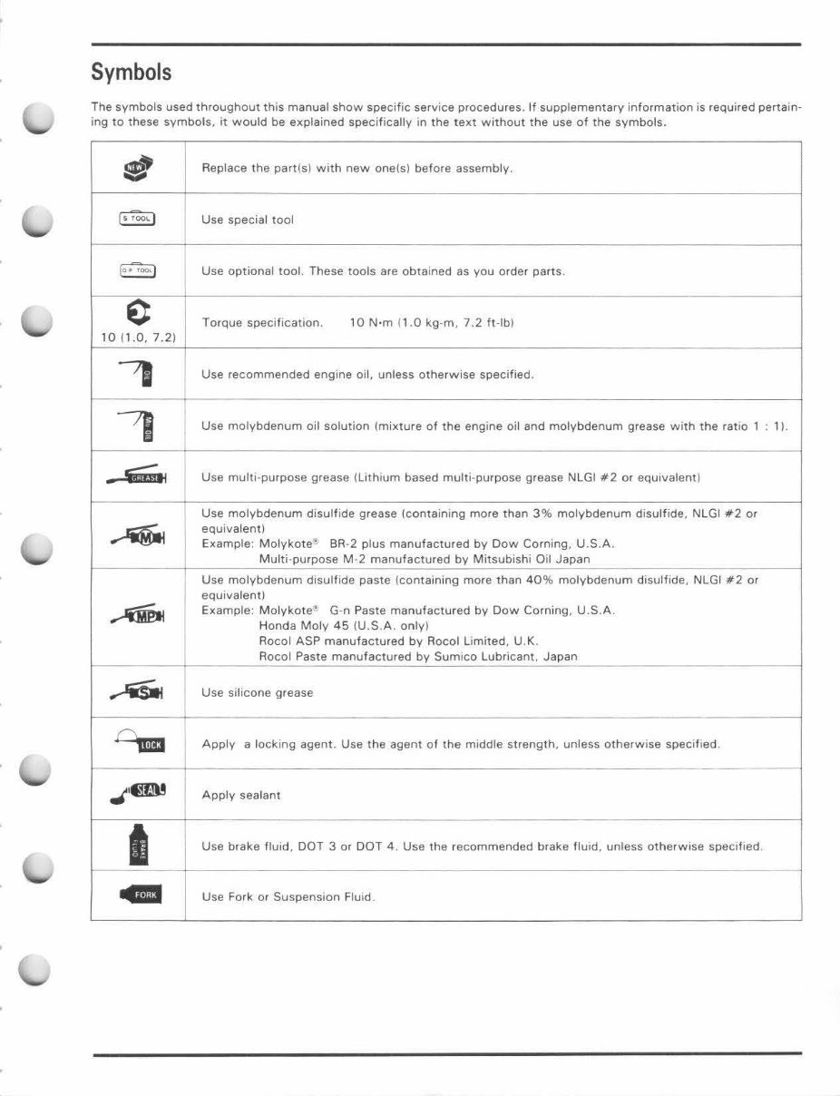
Symbols
The symbols used throughout th is manual show specific service procedures. If supplementary information is required pertain-
ing to these symbols , it would be explained specifically in the text without the use of the symbols .
.. "
-
Replace the part (s) with new one(s) before assembly.
( ~ -;- 00\. )
Use special tool
{o.'"7 "", I
Use optional tool. These tools are obta ined as you order parts .
e Torque specification. 10 N·m ( 1.0 kg -m, 7.2 ft-Ibl
10 ( 1.0, 7.2 1
'I
Use recommended engine oil, unless otherwise specified .
~
Use molybdenum oil solution (mixture of the engine oil and molybdenum grease with the ratio 1 11.
-~
Use mult i- purpose grease i Lithium based mu lti -purpose grease NLGI #2 or equivalent )
Use molybdenum disulfide grease (containing more than 3% molybdenum disulfide , NLGI #2 or
....
equivalent~
Example: Molykote '!. BR -2 plus manufactured by Dow Corning, U.S .A.
Multi -purpose M-2 manufactured by Mitsubishi Oil Japan
Use molybdenum disulfide paste (containing more than 40% molybdenum disulfide, NlGI 112 or
equivalent ~
~
Example: Molykote f!. G-n Paste manufactured by Dow Corning, U.S.A.
Honda Moly 45 (U.S.A. only )
Rocol ASP manufactured by Rocol Limited, U.K.
Rocol Paste manufactured by Sumico Lubricant, Japan
..-'iSitt
Use sil icone grease
o, m
Apply a locking agent. Use the agent 01 the middle strength, unless otherwise specified.
---
J '@ru Apply sealant
I
Use brake fluid. DOT 3 or DOT 4. Use the recommended brake fluid. unless otherwise specified
..
Use Fork or Suspension Fluid .
MEMO
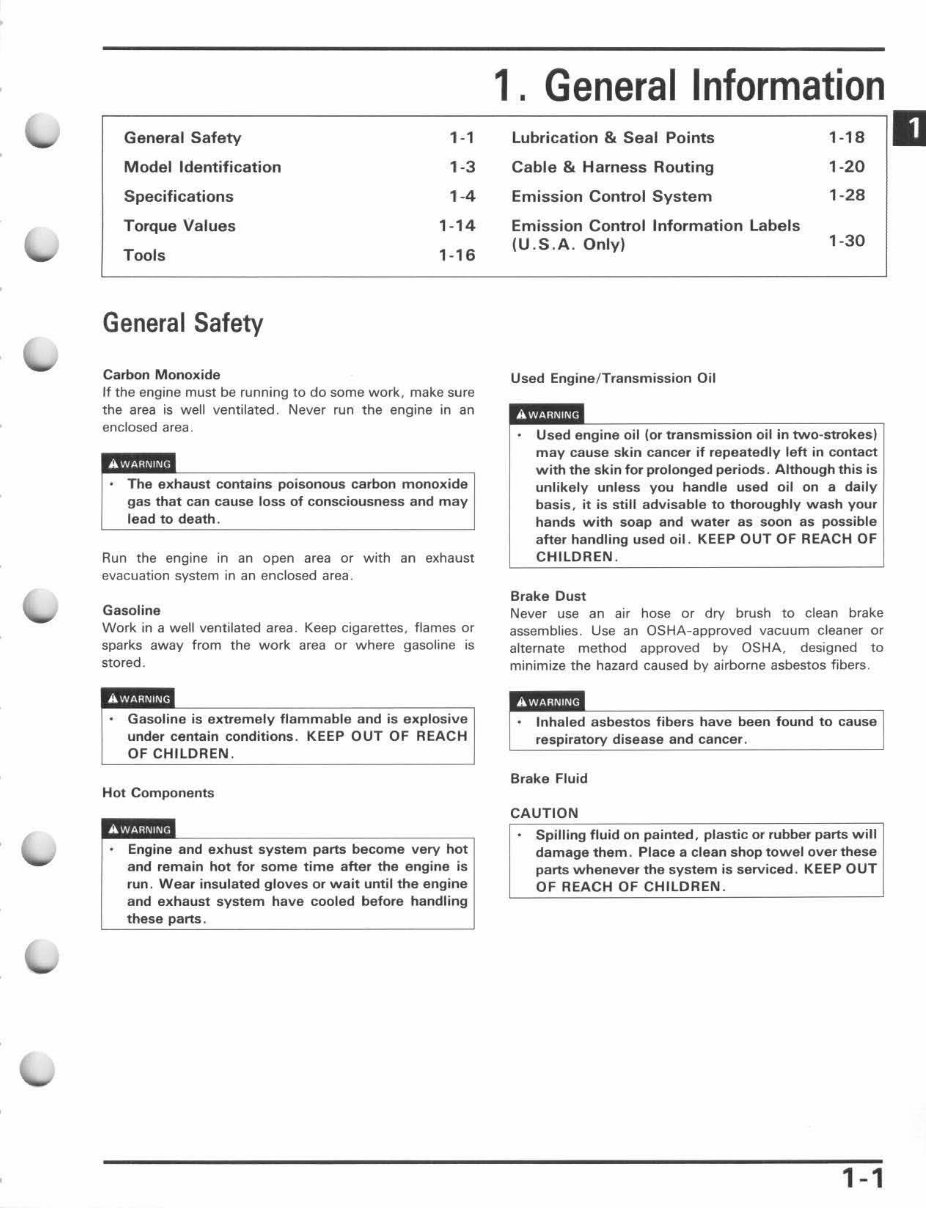
General Safety 1-1
Model Identification 1-3
Specifications 1 -4
Torque Values 1- 14
Tools 1-16
General Safety
Carbon Monoxide
If the engine must be running to do some work, make sure
the area is well ventilated. Never run the engine in an
enclosed area .
The exhaust contains poisonous carbon monoxide
gas that can cause loss of consciousness and may
lead to death .
Run the engine in an open area or with an exhaust
evacuation system in an enclosed area.
Gasoline
Work in a well ventilated area. Keep cigarettes. flames or
sparks away from the wo rk area or where gasoline is
stored.
Gasoline is extremely flammabl e and is explosive
under centain conditions. KEEP OUT OF REACH
OF CHILDREN.
Hot Components
exhust system parts very hot
remain hot for some time after the engine is
run. Wear insulated gloves or wait until the engine
and exhaust system have cooled before handling
these
1. General Information
Lubrication & Seal Points 1-18
Cable & Harness Routing 1 -20
Emission Control System
1- 28
Emission Control Information Labels
(U .S.A. Only)
1-30
Used Engine/ Transmission Oil
Used engine oil (or transmission oil in two-strokes)
may cause skin cancer if repeatedly left in contact
with the skin for prolonged periods. Although this is
unlikely unl ess you handle used oil on a daily
basis, it is still advisable to thoroughly wash your
hands with soap and water as soon as possible
after handling used oil . KEEP OUT OF REACH OF
CHILDREN.
Brake Dust
Never use an air hose or dry brush to clean brake
assemblies. Use an OSHA-approved vacuum cleaner or
alternate method approved by OSHA, designed to
minimize the hazard caused by airborne asbestos fibers.
disease and cancer.
Brake Fluid
CAUTION
Spilling fluid on painted , plastic or rubber parts will
damaga them . Place a clean shop towel over these
parts whenever the system is serviced. KEEP OUT
OF REACH OF CHILDREN.
1-1
II
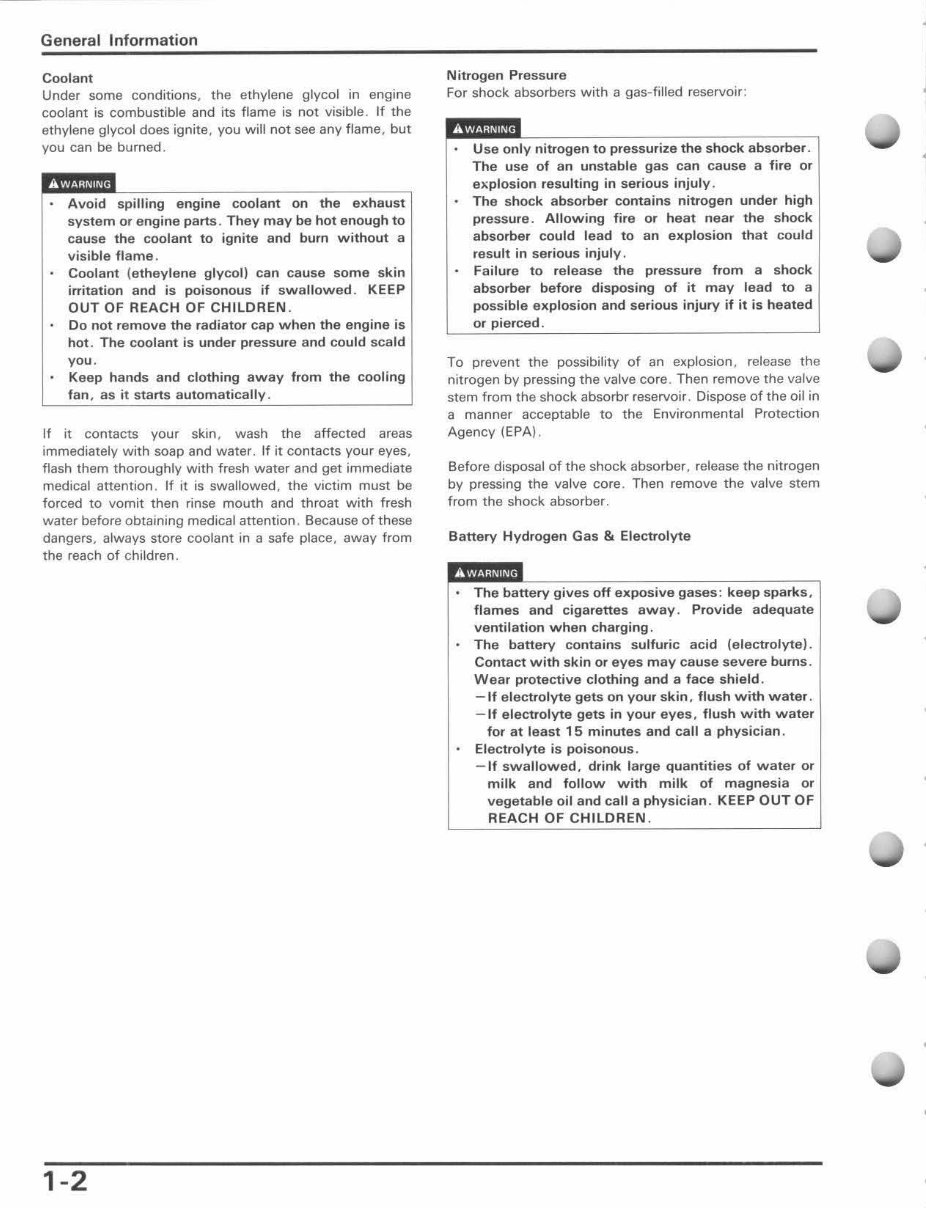
General Information
Coolant
Under some conditions, the eth ylene glycol in engine
coolant is combustible and its flame is not visible . If the
ethylene glycol does ignite, you will not see any flame. but
you can be burned.
Avoid engine coolant on the exhaust
system or i parts . They may be hot enough to
cause th e coolant to ignite and burn without a
visible flame .
Cool ant (etheylene gl ycol) can cause some skin
irritation and is poisonous if swa llowed. KEEP
OUT OF REACH OF CHILDREN .
Do not remove the radiator cap when the engine is
hot. The coolant is under pressure and could scald
you.
Keep hands and clothing away from the cooling
fan , as it starts automaticall y.
If it contacts your skin, wash th e affected areas
immediately with soap and water. If it contacts your eyes,
flash them thoroughly with fresh water and get immediate
medical attention. If it is swallowed, the victim must be
forced to vomit then rinse mou th and th roat with f resh
water before obtaining medical attention. Because of these
dangers, always store coolant in a safe place, away from
the reach of children.
1-2
Nitrogen Pressure
For shock absorbers with a gas-filled reservoir:
Use only nitrogen to absorber.
The use of an unstable gas can cause a fire or
explosion resul ting in serious injuly .
The shock absorber contains nitrogen under high
pressure . Allowing fire or heat near the shock
absorber could lead to an exp losion that could
result in serious injuly .
Failure to rel ease the pressure from a shock
absorber before disposing of it may lead to a
possible explosion and serious injury if it is heated
0'
To prevent the possibility of an explosion, release the
nitrogen by pressing the valve core. Then remove the valve
stem from the shock absorbr reservoir. Dispose of the oil in
a manner acceptable to the Environmental Protection
Agency (EPA) .
Be for e disposal of the shock absorber, release th e nitrogen
by pressing the va lve core. Then remove the valve stem
from the shock absorber.
Battery Hydrogen Gas & Electrolyte
Th e battery gives off exposive gases: keep spa rk s,
flames and cigarettes away . Provide adequate
ventilation when charging.
The battery contains sulfuric acid (electrolyte).
Contact with skin or eyes may cause severe burns .
Wear protective clothing and a face shield.
- If e lectrolyte gets on your skin, flush with water.
- If electrolyte gets in your eyes, flush with water
for at lea st 15 minutes and call a physician .
Electrolyte is poisonous .
- If swallowed, drink large quantities of water or
milk and follow w ith milk of magnesia or
vegetable oil and call a physician . KEEP OUT OF
REACH OF CH ILDREN .
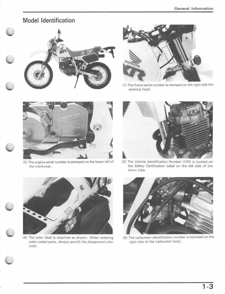
Model Identification
(2) The engine serial number is stamped on the lower leh of
the crankcase.
(4) The color label is attached as shown. When ordering
color-coded parts. always specify the designated color
code.
General Information
(1) The frame serial number is stamped on the right side the
steering head .
(3) The Vehicle Identification Number (VIN) is located on
the Safety Certification Label on the left side of the
down tube .
(5) The carburetor identification number is stamped on the
right side of the carburetor body.
1-3
General In fo rm ati on
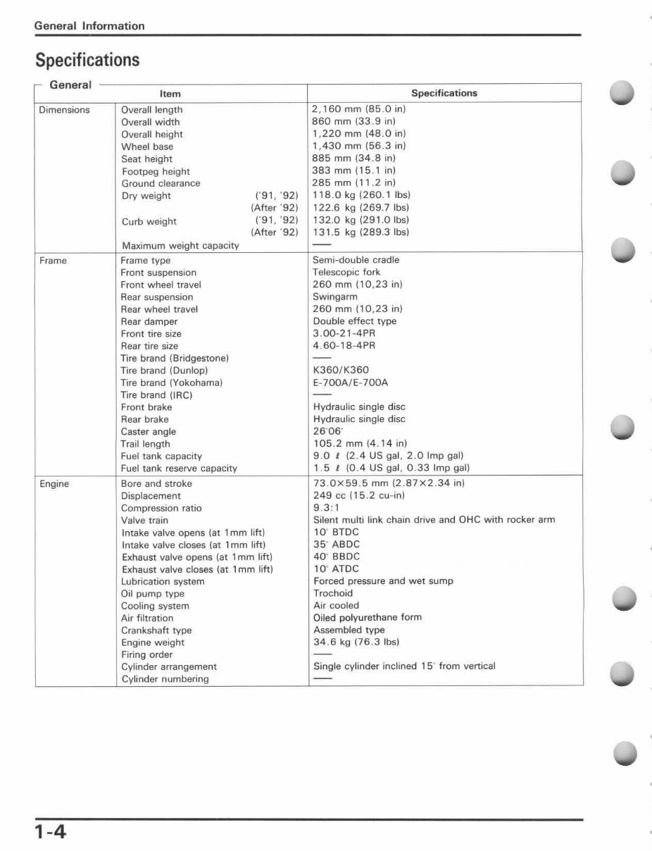
Specifications
r General
Item Speci fi ca ti ons
Dimensions Overall length 2,160 mm (85.0 in)
Overall width 860 mm (33. 9 in)
Overall height 1,220 mm (48 .0 in)
Wheel base 1, 430 mm (56.3 in)
Seat height 885 mm (34 .8 in)
Footpeg height
383 mm (15 . 1 in)
Ground clearance 285 mm (11.2 in)
Dry weight r9 1, ·92) 118 .0 kg (260.1 Ibs)
(After ' 92) 122.6 kg (269 .7 Ibs)
Curb weight
(,91, '92) 132.0 kg (291 .0 Ibs)
(After ·92) 131 .5 kg (289.3 Ibs)
Maximum weight capacity
--
Frame Frame type Semi-double cradle
Front suspension Telescopic fork
Front wheel travel 260 mm ( 10 ,23 in)
Rear suspension Swingarm
Rear wheel travel 260 mm (10,23 in)
Rear damper Double effect type
Front tire size 3.00-21-4PR
Rear tire size 4.60-18-4PR
Tire brand (Bridgestone) --
Tire brand (Dunlop) K360/K360
Tire brand (Yokohama) E -700A/ E -700A
Tire brand (iRC) --
Front brake Hydraulic single disc
Rear brake Hydraulic single disc
Caster angle 26"06·
Trail length 105 .2 mm (4.14 in)
Fuel tank capacity 9.0 I (2.4 US gal, 2 .0 Imp gal)
Fuel tank reserve capacity 1.5 I (0.4 US gal , 0 . 33 Imp gal)
Engine Bore and stroke 73.0x59.5 mm (2.87x2.34 in)
Displacement 249 cc (15 .2 cu-in)
Compression ratio 9. 3: 1
Valve train Silent multi link chain drive and OHC with rocker arm
Intake valve opens (at 1 mm lift) 10' 8TDC
Intake valve closes (at 1 mm lift) 35 " ABDC
Exhaust valve opens (at 1 mm lift) 40' BBDC
Exhaust valve closes (at 1 mm lift) 10' ATDC
Lubrication system Forced pressure and wet sump
Oil pump type Trochoid
Cooling system Air cooled
Air filtration Oiled polyurethane form
Crankshaft type Assembled type
Engine weight 34 .6 kg (76.3 Ibsl
Firing order --
Cylinder arrangement Single cylinder inclined 1 5" from vertical
Cylinder numbering --
1-4
You're Reading a Preview
What's Included?
Fast Download Speeds
Online & Offline Access
Access PDF Contents & Bookmarks
Full Search Facility
Print one or all pages of your manual
$31.99
$41.99
Viewed 54 Times Today


Secure transaction
What's Included?
Fast Download Speeds
Online & Offline Access
Access PDF Contents & Bookmarks
Full Search Facility
Print one or all pages of your manual
$31.99
$41.99
This repair manual covers the 1991-1996 Honda XR250L four-stroke dual sport bike. It includes comprehensive information such as complete tear down and rebuild procedures, part diagrams, torque specifications, maintenance guidelines, and troubleshooting techniques. With 194 pages, this manual provides all the necessary details for professional mechanics and DIY enthusiasts.
Featuring clickable chapters and a searchable interface, users can easily navigate and locate specific information. There are no restrictions on printing or saving/burning to disc, offering convenience and flexibility.
- Complete tear down and rebuild procedures
- Part diagrams and pictures
- Torque specifications
- Maintenance guidelines
- Troubleshooting techniques


