

1979-1984 XR185 / XR200 Service & Repair Manual
What's Included?
Fast Download Speeds
Online & Offline Access
Access PDF Contents & Bookmarks
Full Search Facility
Print one or all pages of your manual
SHOP MANUAL
XR1B5·200
IMPORTANT SAFETY NOTICE
ij#.i@aS Indicates a strong possibility of severe personal injury or loss of life if instructions are
not fo llowed.
CAUTION: Indicates a possibi lity of personal injury or equipment damage if instructions are not
followed.
NOTE: Gi ves he lpful information.
Detailed descriptions of sta ndard workshop procedures, safety principles and service operations are
not included. It is important to note that this manual cont ains some wa rn ings and cautions against
some specific service methods which could cause PERSONAL I NJURY to serv ice personnel or could
damage a vehicle or render it unsafe. Please understand th at those warnings could not cover all con-
ceivable ways in which service, whet her or not recommended by Honda might be done or of t he poss-
ibly hazardous consequences of each conceivable way , nor could Honda investigate all such ways .
Any one using se rvice procedures or tools, whether or not recommended by Honda must sa ti sfy
himself thoroughly t ha t neither personal safety nor vehicle safety will be jeopardized by the service
method or tools selected.
~ HONDA
~ XR200
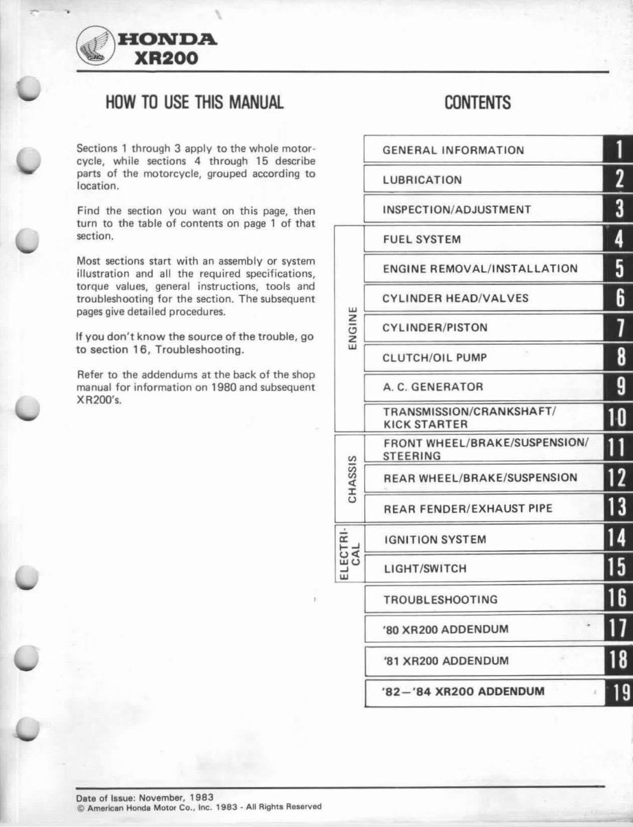
HOW TO USE THIS MANUAL
Sections 1 through 3 apply to the whole motor-
cycle, while sections 4 through 15 describe
parts of the motorcycle, grouped according to
location.
Find the section you want on this page, then
turn to the table of contents on page 1 of that
section.
Most sections start with an assembly or system
illustration and all the required specifications,
torque values, general instructions, tools and
troubleshooting for the section. The subsequent
pages give detailed procedures.
If you don 't know the source of the trouble , go
to section 16 , Troubleshooting.
Refer to the addendums at the back of the shop
manual for information on 1980 and subsequent
XR200's.
Date of Issue: November, 1 983
@ American Honda Motor Co., Inc. 1 983 - All Rights Reserved
CONTENTS
2
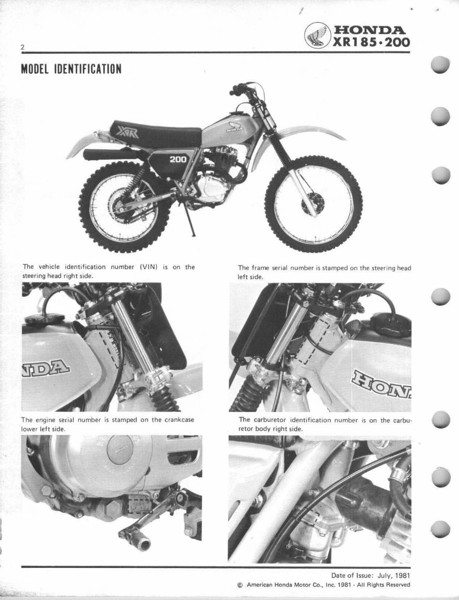
MODEL IDENTIFICATION
The vehicle identification number (VIN) is on the
steering head right side.
The engine serial number is stamped on the crankcase
lower le ft side.
'
HONDA
XR185·200
The frame serial number is stamped on the steering head
left side.
\
The carburetor identification number is on the carbu·
retor body right side.
Date of Issue: July, 1981
© American Honda Motor Co., Inc. 1981 ·All Rights Reserved
~ H~~~A 1. GENERAL INFOMATION 3
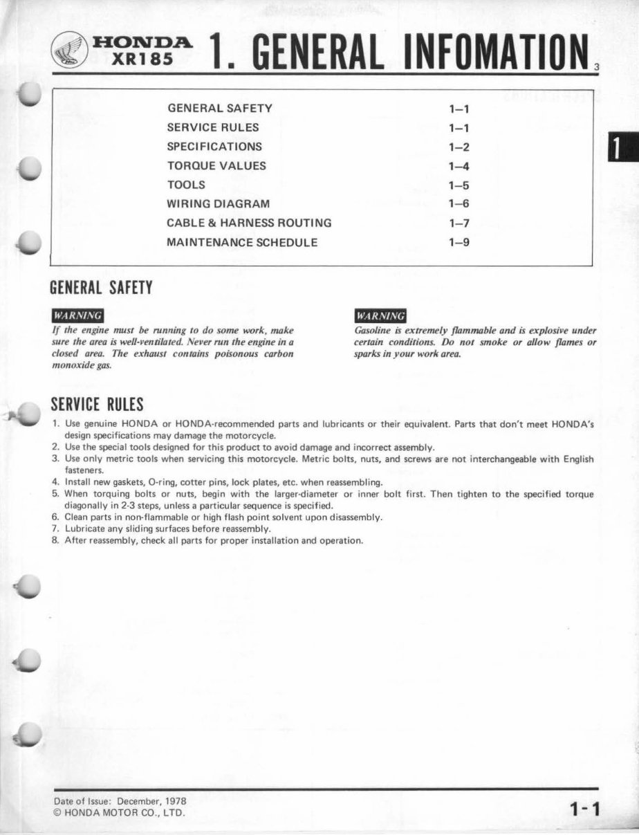
GENERAL SAFETY 1- 1
SE RVI CE RULES 1-1
SPEC IFI CATIONS 1 -2
TORQUE VALUES 1- 4
TOOLS 1 -5
WIR IN G DIAGRAM 1- 6
CABLE & HARNESS ROUTING 1- 7
MAINTENANCE SCHEDULE 1- 9
GENERAL SAFETY
IMijiWli
'M'•Mitd
If rile engine must be nmning to do some work, make
sure the area is well-ventilated. Never run the engine in a
closed area. The exhaust contains poisonous carbon
monoxide gas.
Gasoline is extremely flammable and is explosive under
certain conditions. Do not smoke or allow flames or
sparks in your work area.
SERVICE RULES
1. Use genuine HONDA or HONDA-recommended parts and lubricants or their equivalent. Parts that don't meet HONDA's
design specifications may damage the motorcycle.
2. Use the special tools designed for this product to avoid damage and incorrect assembly.
3. Use only metric tools when servicing this motorcycle. Metric bolts, nuts, and screws are not interchangeable with English
fasteners.
4. Install new gaskets, 0-ring, cotter pins, lock plates, etc. when reassembling.
5. When torquing bolts or nuts, begin with the larger-diameter or inner bolt first. Then tighten to the specified torque
diagonally in 2·3 steps, unless a particular sequence is specified.
6. Clean parts in non-flammable or high flash point solvent upon disassembly.
7. Lubricate any sliding surfaces before reassembly.
8. After reassembly, check all parts for proper installation and operation.
Date of Issue: December, 1978
© HONDA MOTOR CO., LTD. 1-1
4 GEN ERAL INFORMATION
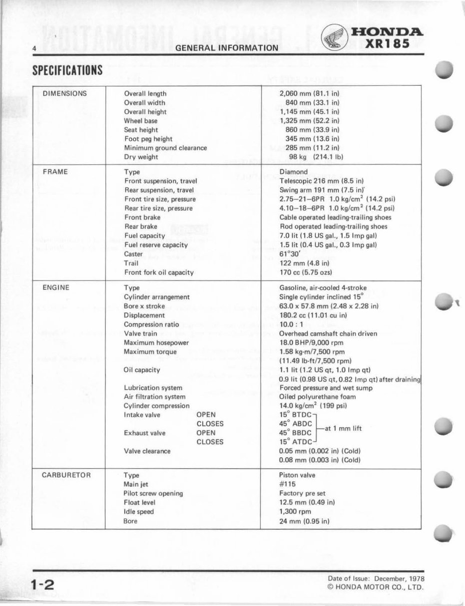
SPECIFICATIONS
DIMENSIONS Overall length
Overall w idth
Overall he ight
Wheel ba se
Seat height
Foot peg height
Minimum ground clearance
Dry weight
FRAME Type
Front suspension, travel
Rear suspension, travel
Front ti re size, pressure
Rear ti re size, pressure
Front brake
Rear brake
Fuel capacity
Fuel reserve capacity
Caster
Trail
Front fork oil capaci ty
ENG I NE Type
Cylinder arrangement
Bore x stroke
Displacement
Compression ratio
Valve t rain
Maximum hosepower
Maximum torque
Oil capacity
Lubrication system
Air filtrat ion system
Cylinder compression
Intake valve OPEN
CLOSES
Exhaust valve OPEN
CLOSES
Valve clearance
CARBURETOR Type
Main jet
Pilot screw opening
Float level
Idle speed
Bore
1-2
2,060 mm (81.1 in)
840 mm (33.1 i n)
1,145 mm (45.1 in)
1,325 mm (52.2 in)
860 mm (33.9 in)
345 mm (13.6 in)
285 mm (11.2 in)
98 kg (214.1 lb)
Diamond
HONDA
XR185
Telescopic 216 mm (8.5 in)
Swing arm 191 mm (7 .5 in)'
2.75- 21- 6PR 1.0 kg/cm
2
(14.2 psi)
4.10- 18-6PR 1.0 kg/cm
2
(14.2 psi)
Cable operated leading·trailing shoes
Rod operated leading·trailing shoes
7.0 lit (1.8 US gal., 1.5 Imp gal)
1.5 lit (0.4 US gal., 0.3 Imp gal)
61 ° 30'
122 mm (4.8 in)
170 cc (5.75 ozs)
Gasoline. air·cooled 4·stroke
Single cylinder incli ned 15°
63 .0 x 57.8 mm (2.48 x 2. 28 in)
180.2 cc ( 11 . 01 cu in)
10.0: 1
Overhead camshaft chain driven
18.0 BHP/9,000 rpm
1.58 kg·mn ,500 rpm
( 11 .49 lb-ft/7 ,500 rpm)
1.11it (1.2USqt,l.Oimpqt)
0 .9 lit (0. 98 US qt. 0.82 I mp qt) after draining
Forced pressure and wet sump
Oiled polyurethane foam
14.0 kg/cm
2
(199 ps i)
45° ABDC .
15° 8TOC}
45
o BBDC at 1 mm lift
15° ATDC
0.05 mm (0.002 in) (Cold)
0.08 mm (0. 003 in) (Cold)
Piston valve
# 115
Factory pre set
12.5 mm (0.49 in)
1,300 rpm
24 mm (0. 95 in)
Date of Issue: December, 1978
© HONDA MOTOR CO .• L TO.
~ HONDA
~ XR18 5
GENERAL INFORMATI ON
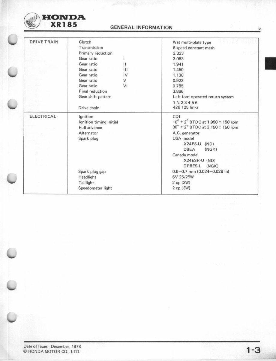
DRIVETRAIN Clutch
Transmission
Primary reduction
Gear ratio
Gear ratio
Gear ratio
Gear ratio
Gear ratio
Gear ratio
Final reduction
Gear shift pattern
Drive chain
ELECTRICAL Ignition
Ignition timing initial
Full advance
Alternator
Spark plug
Spark plug gap
Headlight
Taillight
Speedometer I ight
Date of Issue: December, 1978
© HONDA MOTOR CO., LTO.
I
II
Ill
IV
v
VI
5
Wet multi-plate type
6-speed constant mesh
3.333
3.083
1.941
1.450
1.130
0.923
0.785
3.866
Left foot operated return system
1-N-2-3-4-5-6
428 125 links
CDI
10° ± 2° BTDC at 1,950 ± 150 rpm
30° ± 2° BTDC at 3,150 ± 150 rpm
A.C. generator
USA model
X24ES-U (NO)
D8EA (NGK)
Canada model
X24ESR-U (NO)
DR8ES-L (NGK)
0.6-0.7 mm (0.024-Q.028 in)
6V 25/25W
2 cp (3W)
2 cp (3W)
1-3
6
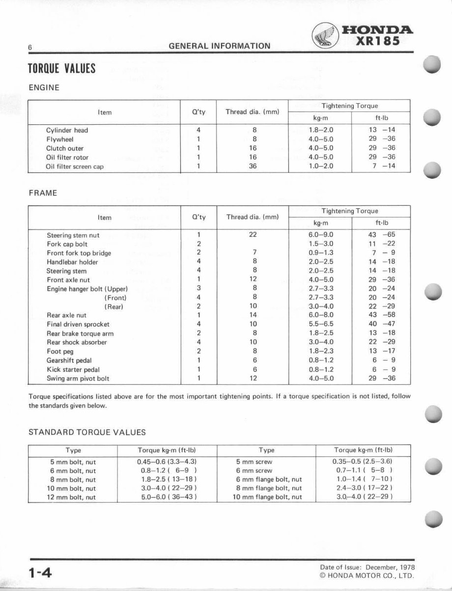
TORQUE VALUES
ENGINE
Item
Cylinder head
Flywheel
Clutch outer
Oil filter rotor
Oil filter screen cap
FRAME
Item
Steering stem nut
Fork cap bolt
Front fork top bridge
Handlebar holder
Steering stem
Front axle nut
Engine hanger bolt (Upper)
(Front)
(Rear)
Rear axle nut
Final driven sprocket
Rear brake torque arm
Rear shock absorber
Foot peg
Gearshift pedal
Kick starter pedal
Swing arm pivot bolt
GENERAL INFORMATION
Q'ty Thread dia. (mm)
4 8
1 8
16
16
36
O'ty Thread dia. (mm)
1 22
2
2 7
4 8
4 8
1 12
3 8
4 8
2 10
1 14
4 10
2 8
4 10
2 8
1 6
1 6
1 12
~ HONDA
~ XR185
Tightening Torque
kg·m ft·lb
1.8-2.0 13 - 14
4.0-5.0 29 -36
4.0-5.0 29 -36
4.0-5 .0 29 -36
1.0-2. 0 7 - 14
Tightening Torque
kg·m ft·lb
6.0-9.0 43 -65
1.5- 3.0 11 -22
0.9-1.3 7 - 9
2.0- 2.5 14 -18
2.0-2.5 14 -18
4.0-5.0 29 -36
2.7-3.3 20 -24
2.7- 3.3 20 -24
· 3.0-4.0 22 -29
6.0-8.0 43 -58
5.5-6 .5 40 - 47
1.8-2.5 13 - 18
3.0-4.0 22 -29
1.8-2.3 13 -17
0.8- 1.2 6 - 9
0.8-1.2 6 - 9
4.0- 5.0 29 -36
Torque specifications listed above are for the most important tightening points. If a torque specification is not listed, follow
the standards given below.
STANDARD TORQUE VA LUES
Type
5 mm bolt. nut
6 mm bolt, nut
8 mm bolt, nut
10 mm bolt, nut
12 mm bolt, nut
1-4
Torque kg-m (ft·lb)
0. 45-0.6 (3.3- 4.3)
0.8- 1.2 ( 6-9 )
1.8-2.5( 13-18)
3.0-4.0 ( 22-29 )
5.0-6.0 ( 36- 43 )
Type
5 mm screw
6 mm screw
6 mm flange bolt, nut
8 mm flange bolt, nut
10 mm flange bolt, nut
Torque kg·m (ft· lb)
0.35- 0.5 (2. 5-3.6)
0.7- 1.1 ( 5-8 )
1. 0-1.4( 7- 10)
2.4- 3.0 ( 17-22)
3.0. -4.0 ( 22- 29 )
Date of Issue : December, 1978
© HONDA MOTOR CO., LTD .
Q\ HONDA
~ XR185
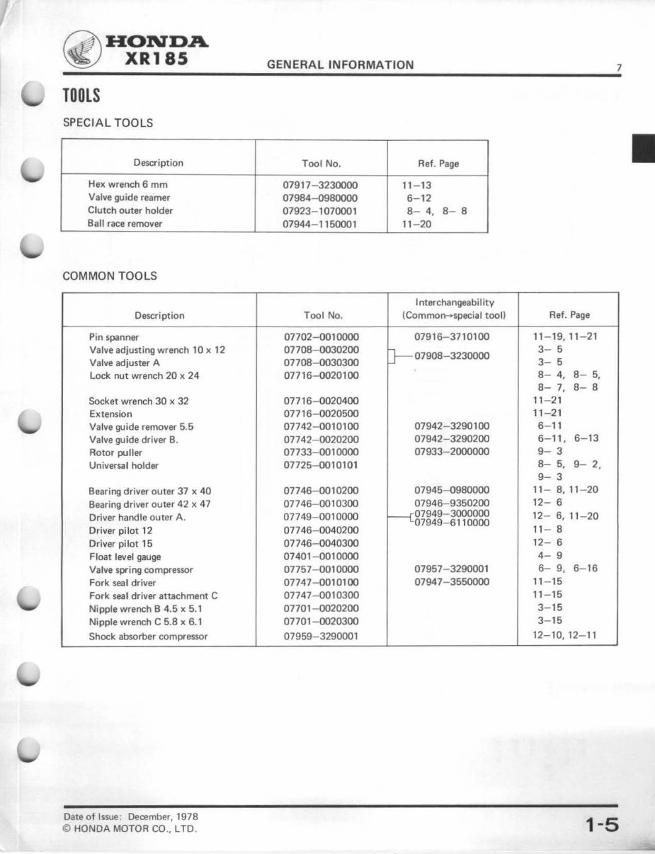
TOOLS
SPECIAL TOOLS
Description
Hex wrench 6 mm
Valve guide reamer
Clutch outer holder
Ball race remover
COMMON TOOLS
Description
Pin spanner
Valve adjusting wrench 10 x 12
Valve adjuster A
Lock nut wrench 20 x 24
Socket wrench 30 x 32
Extension
Valve guide remover 5.5
Valve guide driver B.
Rotor puller
Universal holder
Bearing driver outer 37 x 40
Bearing driver outer 42 x 47
Driver handle outer A.
Driver pilot 12
Driver pilot 15
Float level gauge
Valve spring compressor
Fork seal driver
Fork seal driver attachment C
Nipple wrench B 4.5 x 5.1
Nipple wrench C 5.8 x 6.1
Shock absorber compressor
Date of Issue: December, 1978
© HONDA MOTOR CO., LTO.
GENERAL INFORMATION
7
Tool No. Ref. Page
07917- 3230000 11-13
07984- 0980000 6-12
07923- 1070001 8- 4, 8- 8
07944- 1150001 11-20
Interchangeabi I ity
Tool No. (Common-+special tool) Ref. Page
07702-0010000 07916- 3710100 11 - 19,1 1- 21
07708- 0030200
tr---07908-3230000
3- 5
07708-0030300 3- 5
07716- 00201 00 8- 4, 8- 5,
8- 7, 8- 8
07716- 0020400 11-21
07716- 0020500 11 -21
07742- 0010100 07942- 3290100 6-11
07742- 0020200 07942- 3290200 6- 11, 6- 13
07733- 001 0000 07933 -2000000 9- 3
07725-0010101
8- 5, 9- 2,
9- 3
07746- 0010200 07945- 0980000 11 - 8, 11 - 20
07746- 0010300 07946- 9350200
12- 6
07749- 001 0000
----cP7949-3oooooo
12- 6, 11 -20
07746- 0040200
07949-6 11 0000
11 - 8
07746- 0040300 12- 6
07401- 0010000 4- 9
07757- 0010000 07957-3290001 6- 9, 6- 16
07747- 0010100 07947- 3550000 11-15
07747-0010300 11-15
07701- 0020200 3-15
07701- 0020300 3-15
07959-3290001
12- 10, 12- 11
1-5
~~
2=
o=
=
~
z
0
1-
<
~
a:
0
u.
z
_,
<
a:
w
z
UJ
(!)
CO l
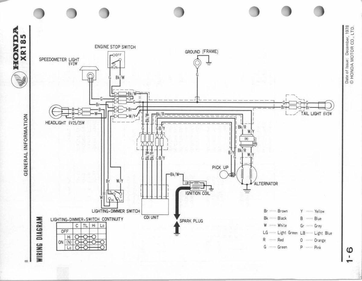
SPE EDOMETER LIGHT
6V3W
ENGINE STOP SWITCH
ral
~~Nf
G Bk/W
GRO~ME)
G
'--- -- r -.... ,
J\ l = "" r J a~~~ c@
'----- ---- -~
1 : B~k/RW .
I : (R)
lk/R
~
LIGHTING· DIMMER SWITCH Y ...... Yell ow
.__ __ ___l
::E
c
LIGHTING.OIMMER. SWITCH CONTINUITY COl UNIT
t SPARK PLUG
Br ······ Brown
Bk ...... Black B ...... Blue
ac:
CD
c
-
c::a
CD
z::
c TL Hi Lo
OFF
Hi
ON (N)
Lo
W ... ... White Gr ...... Grey
LG ...... Li ght Green LB ...... Li gh t Bl ue
R ...... Red 0 .... Orange
G ..... Green P · .. Pink
-
a::
-
=-
co .
r--0
Ol~
~...I
'- .
Q) •
.nO
Eu
eva:
~0
0~
.. o
~~
~~
-o
-z
~0
~I
O (Q)
<0
I
~
You're Reading a Preview
What's Included?
Fast Download Speeds
Online & Offline Access
Access PDF Contents & Bookmarks
Full Search Facility
Print one or all pages of your manual
$31.99
Viewed 96 Times Today


Secure transaction
What's Included?
Fast Download Speeds
Online & Offline Access
Access PDF Contents & Bookmarks
Full Search Facility
Print one or all pages of your manual
$31.99
This repair manual is for the 1979 Honda XR185 and 1980-1984 Honda XR200 four-stroke dirt bikes, excluding the 1984 R version XR200R. It covers complete tear down and rebuild, including pictures and part diagrams, torque specs, maintenance, troubleshooting, and more, spanning 206 pages.
Featuring clickable chapters and a searchable interface, this manual allows for easy navigation to find the necessary information. There are no restrictions on printing or saving/burning to disc.


