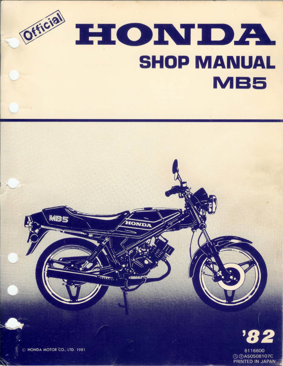
SHOP MANUAL
MB5
Downloaded from www.Manualslib.com manuals search engine
.----- ------ -IMPORTANT SAFETY NOTICE -- -- - - ____,
t\'UI;iil@i Indicates a strong possibility of severe personal injury or loss of life if instructions are not followed.
CAUTION : Indicates a possibility of personal injury or equipment damage if instructions are not followed.
NOTE: Gives helpful! information .
Detailed description of standard workshop procedures, safety principles and service operations are not included. It is
important to note that this manual contains some warnings and caution against some specific serv i ce methods which
could cause PERSONAL I NJURY to service personal or could damage a vehicle or render it unsafe. Please understand
that those warnings could not cover al l conceivable ways in which service, whether or not recommended by Honda might
be done or of the possible ha za rdous consequences of each conceivable way, nore could Honda investigate all such ways.
Anyone using service procedures or tools , whether or not recommended by Honda must satisfy himself thoroughly that
neither personal safety nor vehicle safety will be jeopardized by the service method or too ls selected .
. -..__/
Downloaded from www.Manualslib.com manuals search engine
HONDA
MB5
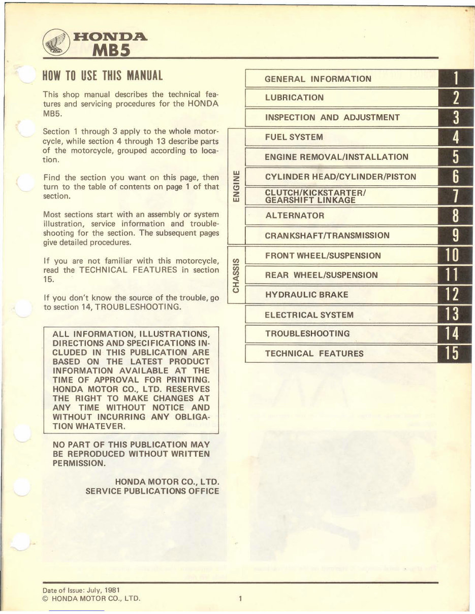
HOW TO USE THIS MANUAL
This shop manual describes the technical fea-
tures and servicing procedures for the HONDA
MB5.
Section 1 through 3 apply to the whole motor-
cycle, while section 4 through 13 describe parts
of the motorcycle, grouped according to loca-
tion.
Find the section you want on this page, then
turn to the table of contents on page 1 of that
section.
Most sections start with an assembly or system
illustration, service information and trouble-
shooting for the section. The subsequent pages
give detail ed procedures.
If you are not familiar with this motorcycle,
read the TECHNICAL FEATURES in section
15.
If you don't know the source of the trouble, go
to section 14, TROUBLESHOOTING.
ALL INFORMATION, ILLUSTRATIONS,
DIRECTIONS AND SPECIFICATIONS IN-
CLUDED IN THIS PUBLICATION ARE
BASED ON THE LATEST PRODUCT
INFORMATION AVAILABLE AT THE
TIME OF APPROVAL FOR PRINTING.
HONDA MOTOR CO., L TO. RESERVES
THE RIGHT TO MAKE CHANGES AT
ANY TIME WITHOUT NOTICE AND
WITHOUT INCURRING ANY OBLIGA-
TION WHATEVER.
NO PART OF THIS PUBLICATION MAY
BE REPRODUCED WITHOUT WRITTEN
PERMISSION.
HONDA MOTOR CO., L TO.
SERVICE PUBLICATIONS OFFICE
Date of Issue: July, 1981
© HONDA MOTOR CO., LTD.
GENERAL INFORMATION
LUBRICATION
INSPECTION AND ADJUSTMENT
FUEL SYSTEM
ENGINE REMOVAL/INSTALLATION
~ CYLINDER HEAD/CYLINDER/PISTON
~ ~==c=L=U=T=C=H=/K==IC=K=S=T=A=R=T=E=R=/============
w GEARSHIFT LINKAGE
(I)
~
:r::
0
ALTERNATOR
CRANKSHAFT/TRANSMISSION
FRONT WHEEL/SUSPENSION
REAR WHEEL/SUSPENSION
HYDRAULIC BRAKE
ELECTRICAL SYSTEM
TROUBLESHOOTING
TECHNICAL FEATURES
Downloaded from www.Manualslib.com manuals search engine
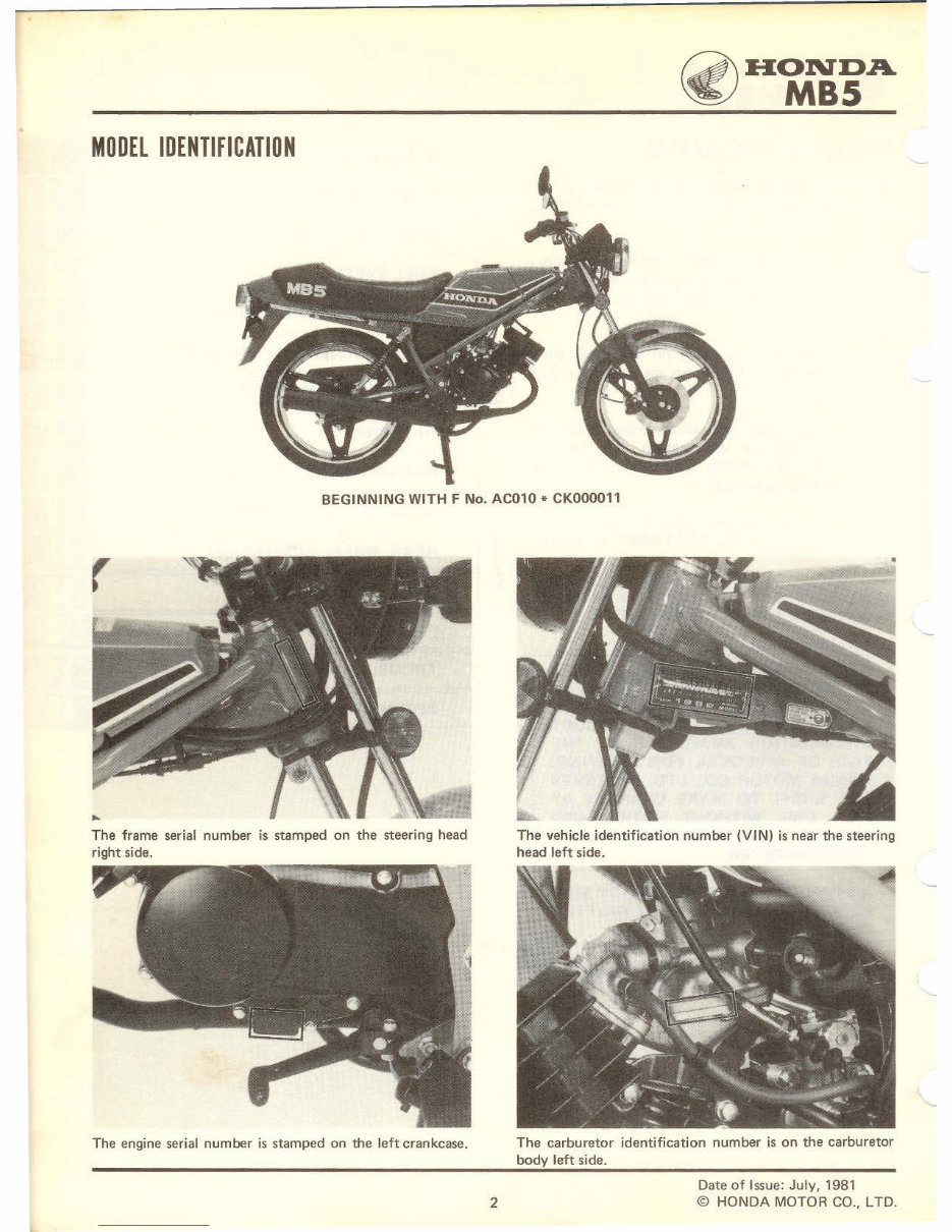
MODEL IDENTIFICATION
~HONDA
~ MBS
BEGINNING WITH F No. AC010 * CK000011
r
.,..
The frame serial number is stamped on the steering head
right side.
The engine serial number is stamped on the left crankcase.
2
The vehicle identification number (VIN) is near the steering
head left side.
The carburetor identification number is on the carburetor
body left side.
Date of Issue: July, 1981
© HONDA MOTOR CO., L TO.
Downloaded from www.Manualslib.com manuals search engine
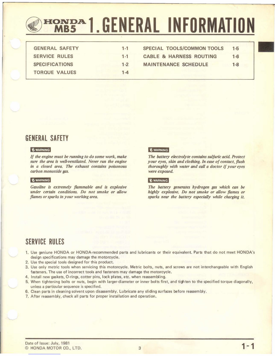
~H~15Al. GENERAL INFORMATION
GENERAL SAFETY
SERVICE RULES
SPECIFICATIONS
TORQUE VALUES
GENERAL SAFETY
1-1
1-1
1-2
1-4
If the engine must be running to do some work, make
sure the area is well-ventilated. Never run the engine
in a closed area. The exhaust contains poisonous
carbon monoxide gas.
Gasoline is extremely flammable and is explosive
under certain conditions. Do not smoke or allow
flames or sparks in your working area.
SERVICE RULES
SPECIAL TOOLS/COMMON TOOLS
CABLE & HARNESS ROUTING
MAINTENANCE SCHEDULE
1-5
1-6
1-8
The battery electrolyte contains sulfuric acid. Protect
your eyes, skin and clothing. In case of contact, flush
thoroughly with water and call a doctor if your eyes
were exposed.
The battery generates hydrogen gas which can be
highly explosive. Do not smoke or allow flames or
sparks near the battery especially while charging it.
1. Use geniune HONDA or HONDA-recommended parts and lubricants or their equivalent. Parts that do not meet HONDA's
design specifications may damage the motorcycle.
2. Use the special tools designed for this product.
3. Use only metric tools when servicing this motorcycle. Metric bolts, nuts, and screws are not interchangeable with English
fasteners. The use of incorrect tools and fasteners may damage the motorcycle.
4. Install new gaskets, 0-rings, cotter pins, lock plates, etc. when reassembling.
5. When tightening bolts or nuts, begin with larger-diameter or inner bolts first, and tighten to the specified torque diagonally,
unless a particular sequence is specified.
6. Clean parts in cleaning solvent upon disassembly. Lubricate any sliding surfaces before reassembly.
7. After reassembly, check all parts for proper installation and operation.
Date of Issue: July, 1981
© HONDA MOTOR CO., L TO. 3
1-1
Downloaded from www.Manualslib.com manuals search engine
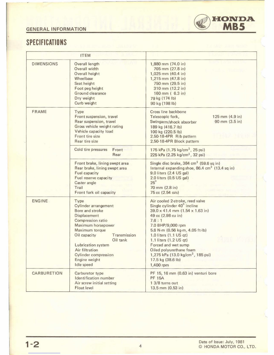
GENERAL INFORMATION
SPECIFICATIONS
DIMENSIONS
FRAME
ENGINE .
CARBURETION
1-2
ITEM
Overall length
Overall width
Overall height
Wheelbase
Seat height
Foot peg height
Ground clearance
Dry weight
Curb weight
Type
Front suspension, travel
Rear suspension, travel
Gross vehicle weight rating
Vehicle capacity load
Front tire size
Rear tire size
Cold tire pressures Front
Rear
Front brake, lining swept area
Rear brake, lining swept area
Fuel capacity
Fuel reserve capacity
Caster angle
Trail
Front fork oil capacity
Type
Cylinder arrangement
Bore and stroke
Displacement
Compression ratio
Maximum horsepower
Maximum torque
Oil capacity Transmission
Oil tank
Lubrication system
Air filtration
Cylinder compression
Engine weight
Idle speed
Carburetor type
Identification number
Air screw initial setting
Float level
4
~HONDA
~ MBS
1,880 mm (74.0 in)
705 mm (27.8 in)
1 ,025 mm (40.4 in)
1,215mm (47.8 in)
750 mm (29.5 in)
310 mm (12.2 in)
160 mm ( 6.3 in)
79 kg (1741b)
90 kg (1981b)
Cross line backbone
Telescopic fork,
Swingarm/shock absorber
189 kg (416.71b)
100 kg (220 .51b)
2.50-18-4PR Rib pattern
2.50-18-4PR Block pattern
175 kPa (1. 75 kg/cm
2
, 25 psi)
225 kPa (2.25 kg/cm
2
, 32 psi)
125 mm (4.9 in)
· 90 mm (3.5 in)
Single disc brake, 384 cm
2
(59.6 sq in)
Internal expanding shoe, 86.4 cm
2
(13.4 sq in)
9.0 liters (2.4 US gal)
2.0 liters (0.5 US gal)
25°
70 mm (2.8 in)
75 cc (2.54 ozs)
Air cooled 2·stroke, reed valve
Single cylinder 40° incline
~9.0 x 41.4 mm (1.54 x 1.63 in)
49 cc (2.98 cu in)
7.6: 1
7.0 BHP/9,000 rpm
5.6 N·m (0.56 kg·m, 4.05 ft·lb)
1.0 liters (1 .1 US qt)
1.1 liters (1.2 US qt)
Forced and wet sump
Oiled polyurethane foam
1,275 kPa ( 13.0 kg/cm
2
, 185 psi)
17.5 kg (38.61b)
1.400 rpm
PF 15, 16 mm (0.63 in) venturi bore
PF 15A
1 3/8 turns out
13.5 mm (0 .53 in)
Date of Issue: July , 1981
© HONDA MOTOR CO., LTD.
Downloaded from www.Manualslib.com manuals search engine
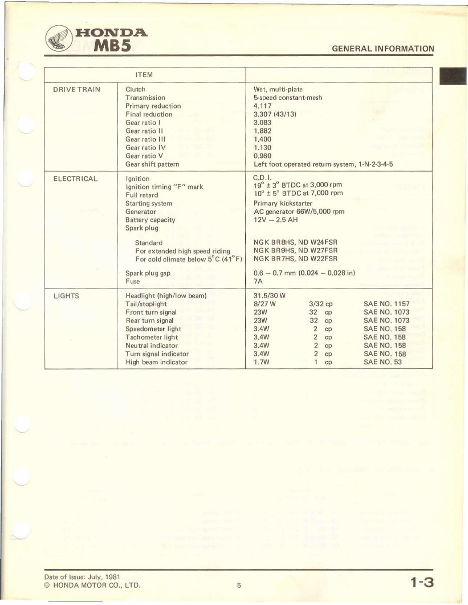
~HONDA
~ MBS
ITEM
DRIVE TRAIN Clutch
Transmission
Primary reduction
Final reduction
Gear ratio I
Gear ratio II
Gear ratio Ill
Gear ratio IV
Gear ratio V
Gear shift pattern
ELECTRICAL Ignition
Ignition timing "F" mark
Full retard
Starting system
Generator
Battery capacity
Spark plug
Standard
For extended high speed riding
For cold climate below 5°C (41°F)
Spark plug gap
Fuse
LIGHTS Headlight (high/low beam)
Tail/stoplight
Front turn signal
Rear turn signal
Speedometer light
Tachometer light
Neutral indicator
Turn signal indicator
High beam indicator
Date of Issue: July, 1981
© HONDA MOTOR CO., LTD. 5
GENERAL INFORMATION
Wet, multi-plate
5-speed constant-mesh
4.117
3.307 (43/13)
3.083
1.882
1.400
1.130
0.960
left foot operated return system, 1-N-2-3-4-5
C.D.I.
19° ± 3° BTDC at 3,000 rpm
10° ± 5° BTDC at 7,000 rpm
Primary kickstarter
AC generator 66W/5,000 rpm
12V- 2.5 AH
NGK BR8HS, ND W24FSR
NGK BR9HS, ND W27FSR
NGK BR7HS, ND W22FSR
0.6 - 0. 7 mm (0.024 - 0.028 in)
7A
31.5/30 w
8/27W 3/32 cp SAE NO. 1157
23W 32 cp SAE NO. 1073
23W 32 cp SAE NO. 1073
3.4W 2 cp SAE NO. 158
3.4W 2 cp SAE NO. 158
3.4W 2 cp SAE NO. 158
3.4W 2 cp SAE NO. 158
1.7W 1 cp SAE NO. 53
1-3
Downloaded from www.Manualslib.com manuals search engine
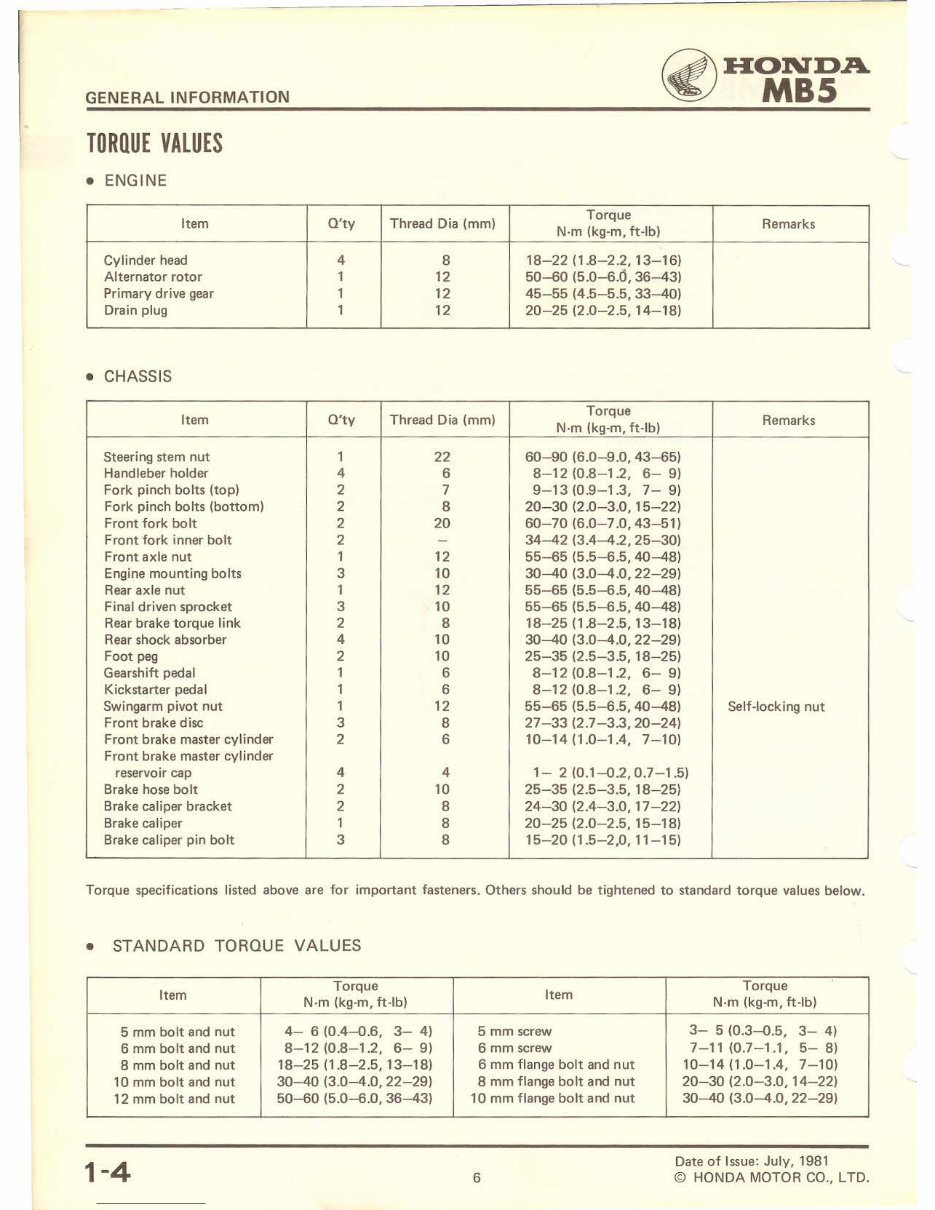
GENERAL INFORMATION
TORQUE VALUES
• ENGINE
~HONDA
~ MBS
Item O'ty Thread Dia (mm)
Torque
Remarks
N-m (kg·m, ft-lb)
Cylinder head 4 8 18-22 (1.8-2.2, 13-16)
Alternator rotor 1 12 50-60 (5.0-6.6, 36-43)
Primary drive gear 1 12 45-55 (4.5-5.5, 33-40)
Drain plug 1 12 20-25 (2.0-2.5, 14-18)
• CHASSIS
Item O'ty Thread Dia (mm)
Torque
Remarks
N·m (kg·m, ft-lb)
Steering stem nut 1 22 60-90 (6.0-9.0, 43-65)
Handleber holder 4 6 8-12 (0.8- 1.2, 6- 9)
Fork pinch bolts (top) 2 7 9-13 (0.9-1.3, 7- 9)
Fork pinch bolts (bottom) 2 8 20-30 (2.0-3.0, 15-22)
Front fork bolt 2 20 60-70 (6.0-7 .0, 43-51)
Front fork inner bolt 2 - 34-42 (3.4-4.2, 25-30)
Front axle nut 1 12 55-65 (5.5-6.5, 40-48)
Engine mounting bolts 3 10 30-40 (3.0-4.0, 22-29)
Rear axle nut 1 12 55-65 (5.5-6.5, 40-48)
Final driven sprocket 3 10 55-65 (5.5-6.5, 40-48)
Rear brake torque link 2 8 18 - 25 (1.8-2.5, 13-18)
Rear shock absorber 4 10 30-40 (3.0-4.0, 22-29)
Foot peg 2 10 25-35 (2.5-3.5, 18-25)
Gearshift pedal 1 6 8-12 (0.8-1.2, 6- 9)
Kickstarter pedal 1 6 8-12 (0.8-1.2, 6- 9)
Swingarm pivot nut 1 12 55-65 (5.5- 6.5, 40-48) Self-locking nut
Front brake disc 3 8 27- 33 (2.7-3.3, 20-24)
Front brake master cylinder 2 6 10-14 (1.0-1.4, 7-10)
Front brake master cylinder
reservoir cap 4 4 1- 2 (0.1-0.2,0.7-1.5)
Brake hose bolt 2 10 25-35 (2.5-3.5, 18-25)
Brake caliper bracket 2 8 24-30 (2.4-3.0, 17-22)
Brake caliper 1 8 20-25 (2.0 -2 .5, 15-18)
Brake caliper pin bolt 3 8 15-20 (1.5-2,0, 11-15)
Torque specifications listed above are for important fasteners. Others should be tightened to standard torque values below.
• STANDARD TORQUE VALUES
Item
Torque
Item
Torque
N-m (kg-m, ft-lb) N-m (kg-m, ft·lb)
5 mm bolt and nut 4- 6 (0.4-0.6, 3- 4) 5 mm screw 3- 5 (0.3-0.5, 3- 4)
6 mm bolt and nut 8-12 (0.8- 1.2, 6- 9) 6 mm screw 7-11 (0.7-1.1, 5-8)
8 mm bolt and nut 18-25 (1.8-2.5, 13-18) 6 mm flange bolt and nut 10-14 (1.0-1.4, 7-10)
10 mm bolt and nut 30-40 (3.0-4.0, 22-29) 8 mm flange bolt and nut 20-30 (2.0-3.0, 14-22)
12 mm bolt and nut 50-60 (5.0-6.0, 36-43) 10 mm flange bolt and nut 30-40 (3.0-4.0, 22 - 29)
1-4
6
Date of Issue: July, 1981
© HONDA MOTOR CO., LTO.
Downloaded from www.Manualslib.com manuals search engine
~HONDA
~ MBS
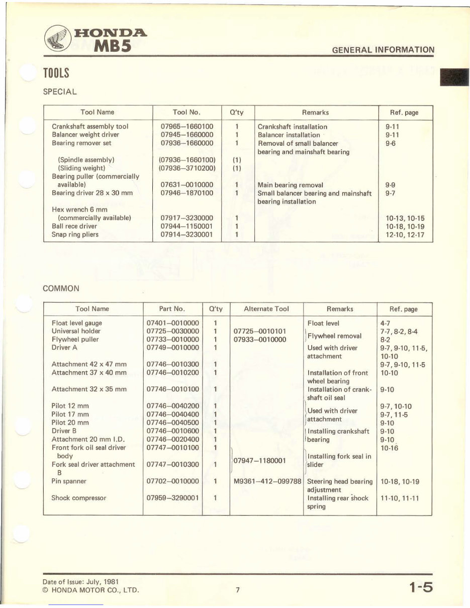
TOOLS
SPECIAL
Tool Name Tool No.
Crankshaft assembly tool 07965-1660100
Balancer weight driver 07945- 1660000
Bearing remover set 07936- 1660000
(Spind le assembly) (07936-1660100)
(Slid i ng weight) (07936-3710200)
Bearing puller (commercially
available) 07631-0010000
Bearing driver 28 x 30 mm 07946-1870100
Hex wrench 6 mm
(commercially available) 07917- 3230000
Ball rece driver 07944- 1150001
Snap ring pliers 07914-3230001
COMMON
Tool Name Part No. O'ty
Float level gauge 07401-0010000 1
Universal holder 07725-0030000 1
Flywheel puller 07733-0010000 1
Driver A 077 49-001 0000 1
Attachment 42 x 47 mm 077 46-0010300 1
Attachment 37 x 40 mm 077 46-001 0200 1
Attachment 32 x 35 mm 07746-0010100 1
Pilot 12 mm 07746-0040200 1
Pilot 17 mm 07746-0040400 1
Pilot 20 mm 07746-0040500 1
Driver B 07746-0010600 1
Attachment 20 mm 1.0. 07746-0020400 1
Front fork oil seal driver 07747-0010100 1
body
Fork seal driver attachment 07747-0010300 1
B
Pin spanner 07702-0010000 1
Shock compressor 07959-3290001 1
Date of Issue: July, 1981
© HONDA MOTOR CO., LTO.
GENERAL INFORMATION
O'ty Remarks Ref. page
1 Crankshaft installation 9-11
1 Balancer installation 9-11
1 Removal of small balancer 9-6
bearing and mainshaft bearing
(1)
(1)
1 Main bearing removal 9-9
1 Small balancer bearing and mainshaft 9-7
bearing installation
1 10-13, 10-15
1 10-18, 10-19
1 12-10, 12-17
Alternate Tool Remarks Ref. page
Float level 4-7
07725-0010101
J Flywheel removal
7-7' 8-2,8-4
07933-0010000 8-2
Used with driver 9-7,9-10,11-5,
attachment 10-10
9-7,9-10,11-5
Installation of front 10-10
wheel bearing
Installation of crank- 9-10
shaft oil seal
} U•od w;th dd"'
9-7,10-10
9-7,11-5
attachment
9-10
~ Installing crankshaft 9-10
bearing 9-10
r 7947 - 1180001
10-16
}ln.tamng fo'k "''' ;n
slider
M9361-412-099788 Steering head bearing 10-18, 10-19
adjustment
Installing rear shock 11-10, 11-11
spring
7
1-5
Downloaded from www.Manualslib.com manuals search engine
GENERAL INFORMATION
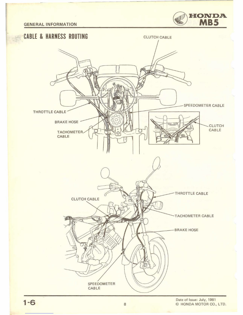
CABLE & HARNESS ROUTING
1-6
BRAKE HOSE
TACHOMETER
CABLE
CLUTCH CABLE
8
~HONDA
~ MBS
SPEEDOMETER CABLE
THROTTLE CABLE
CLUTCH
CABLE
TACHOMETER CABLE
Date of Issue: July, 1981
© HONDA MOTOR CO., LTD.
Downloaded from www.Manualslib.com manuals search engine
You're Reading a Preview
What's Included?
Lifetime Access
Access PDF Contents & Bookmarks
Print one or all pages of your manual