1994 HONDA GOLDWING GL1500 ASPENCADE, SE, INTERSTATE Service Repair Manual !!!
What's Included?
Lifetime Access
Fast Download Speeds
Online & Offline Access
Access PDF Contents & Bookmarks
Full Search Facility
Print one or all pages of your manual
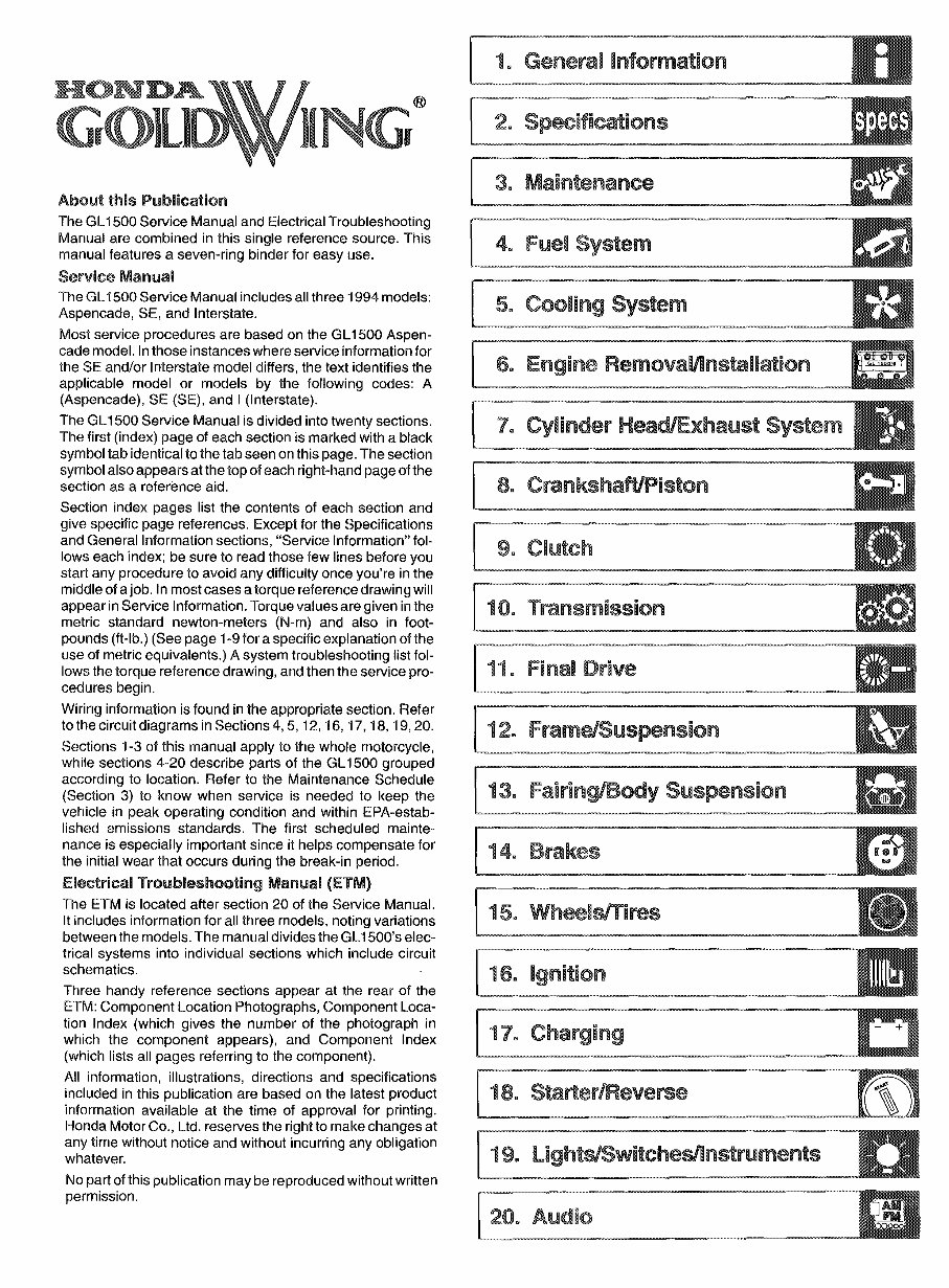
3. Maintenance 5. Cooling System 4. Fuel System 19. lightsiSwitchesilnstrument:s 17. Charging 13. Fairing/Body Suspension 10. Transmission ~. AUdi~: ~ 5. WheelslTires ~1. Final Drive [!""2. Fra~m~sus~en~ion [-":7. ~Cylinde~ H~~Xhaust Syste [ 8.::Crank~ha~;;._t_o_n~__~_ [ 9. Clutch ® About this Publication The GL1500 Service Manual and Electrical Troubleshooting Manual are combined in this single reference source. This manual features a seven-ring binder for easy use. Service Manual The GL1500 Service Manual includes all three 1994 models: Aspencade, SE, and Interstate. Most service procedures are based on the GL1500 Aspen- cade model. In those instances where service information for the SE and/or Interstate model differs, the text identifies the applicable model or models by the following codes: A (Aspencade), SE (SE), and I (Interstate). The GL1500 Service Manual is divided into twenty sections. The first (index) page of each section is marked with a black symbol tab identical to the tab seen on this page. The section symbol also appears at the top of each right-hand page of the section as a reference aid. Section index pages list the contents of each section and give specific page references. Except for the Specifications and General Information sections, "Service Information" fol- lows each index; be sure to read those few lines before you start any procedure to avoid any difficulty once you're in the middle of a job. In most cases a torque reference drawing will appear in Service Information. Torque values are given in the metric standard newton-meters (N-m) and also in foot- pounds (ft-Ib.) (See page 1-9 for a specific explanation of the use of metric equivalents.) A system troubleshooting list fol- lows the torque reference drawing, and then the service pro- cedures begin. Wiring information is found in the appropriate section. Refer to the circuit diagrams in Sections 4,5, 12, 16, 17, 18, 19,20. Sections 1-3 of this manual apply to the whole motorcycle, while sections 4-20 describe parts of the GL1500 grouped according to location. Refer to the Maintenance Schedule (Section 3) to know when service is needed to keep the vehicle in peak operating condition and within EPA-estab- lished emissions standards. The first scheduled mainte- nance is especially important since it helps compensate for the initial wear that occurs during the break-in period. Electrical Troubleshooting Manual (ETM) The ETM is located after section 20 of the Service Manual. It includes information for all three models, noting variations between the models. The manual divides the GL1500's elec- trical systems into individual sections which include circuit schematics. Three handy reference sections appear at the rear of the ETM: Component Location Photographs, Component Loca- tion Index (which gives the number of the photograph in which the component appears), and Component Index (which lists all pages referring to the component). All information, illustrations, directions and specifications included in this publication are based on the latest product information available at the time of approval for printing. Honda Motor Co., Ltd. reserves the right to make changes at any time without notice and without incurring any obligation whatever. No part of this publication may be reproduced without written permission. HONDA L
General Information Service Safety .... D • • • •• 1 ..2 Model Identification . D • •• 1 ..4 Emission Control Systems D • • • •• 1 ..5 Emission Control Information labels .. .. 1 ..8 Metric Conversions 1 ..9 N.P.S. Part Numbers 1 ..10 Tools 1..11 1.. 1
General Information Service Safety IMPORTANT SAFETY NOTICE. ------------- Detailed descriptions of standard workshop procedures, safety principles and service operations are not included. It is important to note that this manual contains some warnings and cautions against some specific service methods which could cause PERSONAL INJURY to service personnel or could damage a vehicle or render it unsafe. Please understand that these warnings could not cover all conceivable ways in which service, whether or not recom- mended by Honda, might be done or of the possibly hazardous consequences of each conceivable way, nor could Honda investigate all such ways. Anyone using service procedures or tools, whether or not recommended by Honda, must satisfy himself thoroughly that neither personal safety nor vehicle safety will be jeopardized by the service methods or tools selected. Pay special attention to statements preceded by these symbols o Indicates a strong possibility of severe per- sonal injury or death if instructions are not followed. CAUTION .. Indicates a possibility of personal injury or equipment damage if instructions are not followed. NOTE $ Gives helpful information. "The exhaust contains poisonous carbon monoxide gas that can cause loss of con- sciommess and may lead to death. Some specific warnings and cautions found in this manual follow: Carbon Monoxide If the engine must be running to do some work, make sure the area is well ventilated. Never run the engine in an enclosed area. -- -------_...._-- Used Enginerrransmission on ---------- .. Used engine on (or transmission oil in two- strokes) may cause skin cancer if repeatedly left in contact with the skin for prolonged peri- ods. Although this is unlikely unless you han- dle used oU on a daily basis, it is still advisable to thoroughly wash your hands with soap and water as soon as possible after handling used oil. KEEP OUT OF REACH OF CHILDREN. Run the engine in an open area or with an exhaust evac- uation system in an enclosed area. Gasoline Work in a well ventilated area. Keep cigarettes, flames or sparks away from the work area or where gasoline is stored. $ Gasoline is extremely flammable and is explo- sive under certain conditions. KEEP OUT OF REACH OF CHILDREN. Hot Components rBII_.... _ " Engine and exhaust system parts become very hot and remain hot for some time after the engine is run. Wear insulated gloves or wait until the engine and exhaust system have cooled before handling these parts. 1=2 Battery Hydrogen Gas & Electrolyte _L ..... _ o The battery gives off explosive gases; keep sparks, flames and cigarettes away. Provide adequate ventilation when charging. " The battery contains sulfuric acid (electrolyte). Contact with skin or eyes may cause severe burns. Wear protective clothing and a face shield. - If electrolyte gets on your skin, flush with water. - If electrolyte gets in your eyes, flush with water for at least 15 minutes and call a physician. .. Electrolyte is poisonous - If swallowed, drink large quantities of water or milk and follow with milk of magnesia or vegetable oil and call a physician. KEEP OUT OF REACH OF CHILDREN.
Brake Dust Brake dust may contain asbestos. Never use an air hose or dry brush to clean brake assemblies. Use an OSHA approved vacuum cleaner or alternate method approved by OSHA, designed to minimize the hazard caused by airborne asbestos fibers. o Inhaled asbestos fibers have been found to cause respiratory disease and cancer. Brake Fluid CAUTION " Spilling fluid on painted, plastic or rubber parts will damage them. Place a clean shop towel over these parts whenever the system is serviced. KEEP OUT OF REACH OF CHILDREN. Coolant Under some conditions, the ethylene glycol in engine coolant is combustible and its flame is not visible. If the ethylene glycol does ignite, you will not see any flame, but you can be burned. CAUTION " Avoid spilling engine coolant on the exhaust system or engine parts. They may be hot enough to cause the coolant to ignite and bum without a visible flame. @ Coolant (ethylene glycol) can cause some skin irritation and is poisonous if swallowed. KEEP OUT OF REACH OF CHILDREN. o Do not remove the radiator cap when the engine is hot. The coolant is under pressure and could scald you. @ Keep hands and clothing away from the cool· ing fan, as it starts automatically. General Service Rules 1. Use genuine HONDA or HONDA-recommended parts and lubricants or their equivalents. Parts that do not meet HONDA's design specifications may damage the motorcycle. 2. Use the special tools designed for this prodUCt. 3. Use only metric tools when servicing this motorcycle. Metric bolts, nuts, and screws are not interchange- able with English fasteners. The use of incorrect tools and fasteners may damage the motorcycle. Coolant (cont'd) If coolant contacts your skin, wash the affected areas immediately with soap and water. If it contacts your eyes, flush them thoroughly with fresh water and get immediate medical attention. If it is swallowed, the vic- tim must be forced to vomit then rinse mouth and throat with fresh water before obtaining medical attention. Because of these dangers, always store coolant in a safe place, away from the reach of children. Nitrogen Pressure For shock absorbers with a gas-filled reservoir: !BIL , _ o Use only nitrogen to pressurize the shock absorber. The use of an unstable gas can cause a fire or explosion resulting in serious injury. .. The shock absorber contains nitrogen lmder high pressure. Allowing fire or heat near the shock absorber could lead to an explosion that could result in serious injury. .. Failure to release the pressure from a shock absorber before disposing of it may lead to a possible explosion and serious injury if it is heated or pierced. To prevent the possibility of an explosion, release the nitrogen by pressing the valve core. Then remove the valve stem from the shock absorber reservoir. Dispose of the oil in a manner acceptable to the Environmental Protection Agency (EPA). Before disposal of the shock absorber, release the nitro- gen by pressing the valve core. Then remove the valve stem from the shock absorber. 4. Install new gaskets, O-rings, cotter pins, lock plates, etc. when reassembling. 5. When tightening a series of bolts or nuts, begin with the larger-diameter or inner bolts first, and tighten to the specified torque diagonally, unless a particular sequence is specified. 6. Clean parts in cleaning solvent upon disassembly. Lubricate any sliding surfaces before reassembly. 7. After reassembly, check all parts for proper installa- tion and operations. 1-3
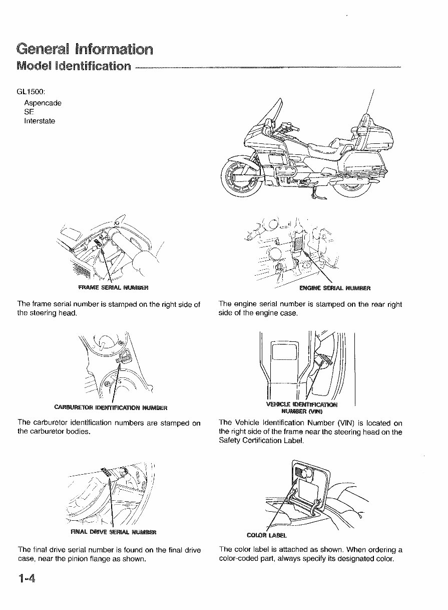
General Information Model Identification ~,~,~,,~,,_===="W~ ~ =ww GL1500: Aspencade SE Interstate The frame serial number is stamped on the right side of the steering head. The carburetor identification numbers are stamped on the carburetor bodies. The final drive serial number is found on the final drive case, near the pinion flange as shown. The engine serial number is stamped on the rear right side of the engine case. 19J\ -"'-,, II 'VEHICLE 1D9ITIFICATlOOJ IIlUM8ERMIIlI The Vehicle Identification Number (VIN) is located on the right side of the frame near the steering head on the Safety Certification Label. The color label is attached as shown. When ordering a color-coded part, always specify its designated color.
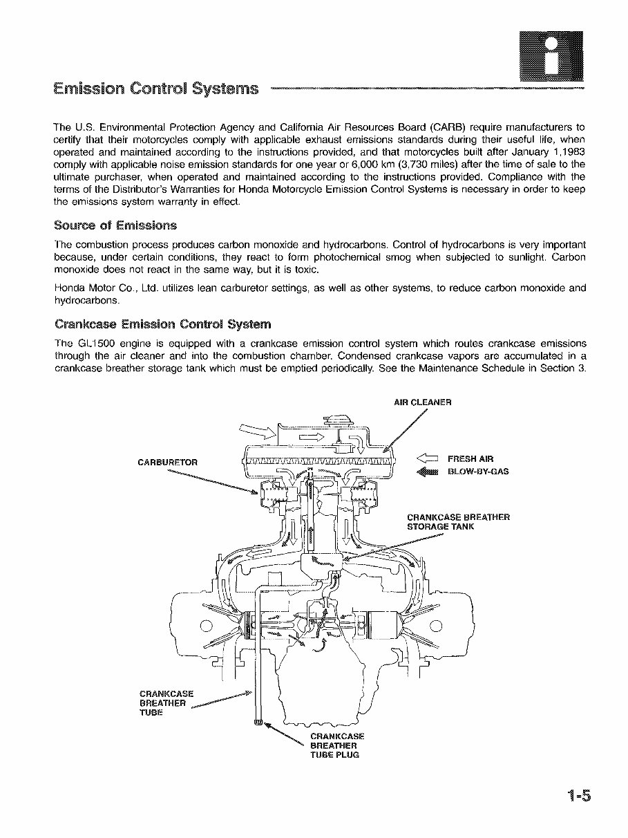
Emission Control Systems The U.S. Environmental Protection Agency and California Air Resources Board (CARB) require manufacturers to certify that their motorcycles comply with applicable exhaust emissions standards during their useful life, when operated and maintained according to the instructions provided, and that motorcycles built after January 1,1983 comply with applicable noise emission standards for one year or 6,000 km (3,730 miles) after the time of sale to the ultimate purchaser, when operated and maintained according to the instructions provided. Compliance with the terms of the Distributor's Warranties for Honda Motorcycle Emission Control Systems is necessary in order to keep the emissions system warranty in effect. Source of Emissions The combustion process produces carbon monoxide and hydrocarbons. Control of hydrocarbons is very important because, under certain conditions, they react to form photochemical smog when subjected to sunlight. Carbon monoxide does not react in the same way, but it is toxic. Honda Motor Co., Ltd. utilizes lean carburetor settings, as well as other systems, to reduce carbon monoxide and hydrocarbons. Crankcase Emission Control System The GL1500 engine is equipped with a crankcase emission control system which routes crankcase emissions through the air cleaner and into the combustion chamber. Condensed crankcase vapors are accumulated in a crankcase breather storage tank which must be emptied periodically. See the Maintenance Schedule in Section 3. CRANKCASE ~ BREATHER _____ TUBE CRANKCASE BREATHER TUBE PLUG
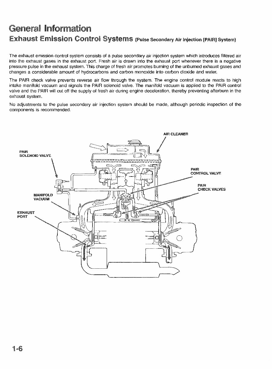
General Information Exhaust Emission Control Systems (Pulse Secondary Air Injection [PAIR] System) The exhaust emission control system consists of a pulse secondary air injection system which introduces filtered air into the exhaust gases in the exhaust port. Fresh air is drawn into the exhaust port whenever there is a negative pressure pulse in the exhaust system. This charge of fresh air promotes burning of the unburned exhaust gases and changes a considerable amount of hydrocarbons and carbon monoxide into carbon dioxide and water. The PAIR check valve prevents reverse air flow through the system. The engine control module reacts to high intake manifold vacuum and signals the PAIR solenoid valve. The manifold vacuum is applied to the PAIR control valve and the PAIR will cut off the supply of fresh air during engine deceleration, thereby preventing afterburn in the exhaust system. No adjustments to the pulse secondary air injection system should be made, although periodic inspection of the components is recommended. PAIR SOLENOID VALVE \ EXHAUST PORT PAIR CONTROL VALVE PAIR CHECK VALVES
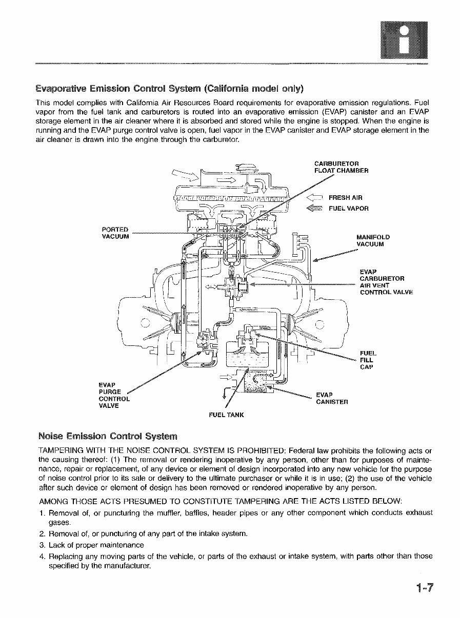
Evaporative Emission Control System (California. model only) This model complies with California Air Resources Board requirements for evaporative emission regulations. Fuel vapor from the fuel tank and carburetors is routed into an evaporative emission (EVAP) canister and an EVAP storage element in the air cleaner where it is absorbed and stored while the engine is stopped. When the engine is running and the EVAP purge control valve is open, fuel vapor in the EVAP canister and EVAP storage element in the air cleaner is drawn into the engine through the carburetor. EVAP PURGE CONTROL VALVE CARBURETOR FLOAT CHAMBER FRESH AIR FUEL VAPOR MANIFOLD VACUUM ~ EVAP CARBURETOR "'--~~+""'i=---~ AIR VENT CONTROL VALVE FUEL FILL CAP Noise Emission Control System TAMPERING WITH THE NOISE CONTROL SYSTEM IS PROHIBITED: Federal law prohibits the following acts or the causing thereof: (1) The removal or rendering inoperative by any person, other than for purposes of mainte- nance, repair or replacement, of any device or element of design incorporated into any new vehicle for the purpose of noise control prior to its sale or delivery to the ultimate purchaser or while it is in use; (2) the use of the vehicle after such device or element of design has been removed or rendered inoperative by any person. AMONG THOSE ACTS PRESUMED TO CONSTITUTE TAMPERING ARE THE ACTS LISTED BELOW: 1. Removal of, or puncturing the muffler, baffles, header pipes or any other component which conducts exhaust gases. 2. Removal of, or puncturing of any part of the intake system. 3. Lack of proper maintenance 4. Replacing any moving parts of the vehicle, or parts of the exhaust or intake system, with parts other than those specified by the manufacturer. 1=7
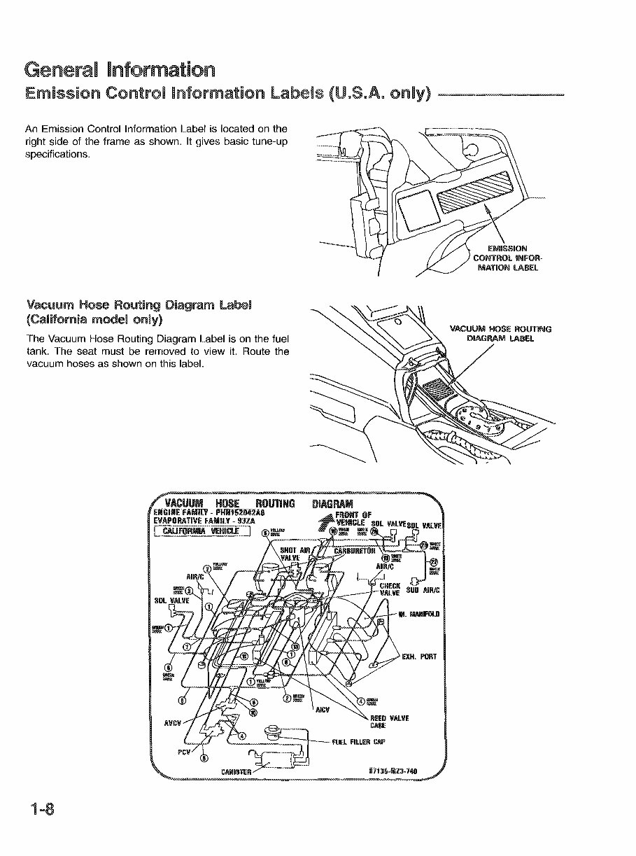
General Information Emission Control Information labels (U.S.A. only) An Emission Control Information Label is located on the right side of the frame as shown. It gives basic tune-up specifications. EMISSION CONTROL INFOR· MATHON LABEL Vacuum Hose Routing Diagram label (Califomi«:n model only) The Vacuum Hose Routing Diagram Label is on the fuel tank. The seat must be removed to view it. Route the vacuum hoses as shown on this label. REED VALVE ~ CAllE 4 ~ . fUEL fiLLER CAP CANISTE~Il'j:J!i-i1n:J-740 1-8
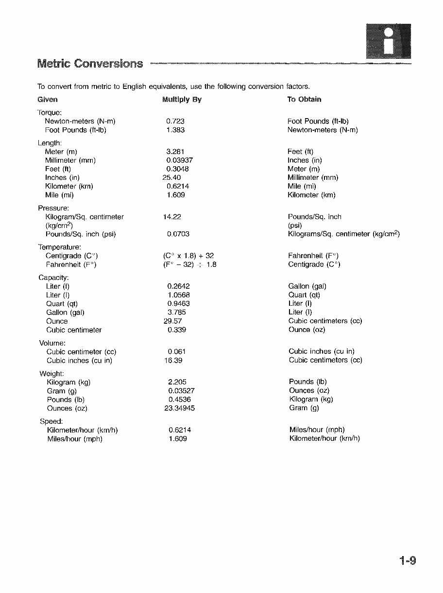
Metric Conversions To convert from metric to English equivalents, use the following conversion factors. Given Multiply By To Obtain Torque: Newton-meters (N-m) 0.723 Foot Pounds (ft-Ib) Foot Pounds (ft-Ib) 1.383 Newton-meters (N-m) Length: Meter (m) 3.281 Feet (ft) Millimeter (mm) 0.03937 Inches (in) Feet (ft) 0.3048 Meter (m) Inches (in) 25.40 Millimeter (mm) Kilometer (km) 0.6214 Mile (mi) Mile (mi) 1.609 Kilometer (km) Pressure: Kilogram/Sq. centimeter 14.22 Pounds/Sq. inch (kg/cm 2 ) (psi) Pounds/Sq. inch (psi) 0.0703 Kilograms/Sq. centimeter (kg/cm 2 ) lemperature: Centigrade (CO) (CO x 1.8) + 32 Fahrenheit (FO) Fahrenheit (P) (FO - 32) 7 1.8 Centigrade (CO) Capacity: Liter (I) 0.2642 Gallon (gal) Liter (I) 1.0568 Quart (qt) Quart (qt) 0.9463 Liter (I) Gallon (gal) 3.785 Liter (I) Ounce 29.57 Cubic centimeters (cc) Cubic centimeter 0.339 Ounce (oz) Volume: Cubic centimeter (cc) 0.061 Cubic inches (cu in) Cubic inches (cu in) 16.39 Cubic centimeters (cc) Weight: Kilogram (kg) 2.205 Pounds (Ib) Gram (g) 0.03527 Ounces (oz) Pounds (Ib) 0.4536 Kilogram (kg) Ounces (oz) 23.34945 Gram (g) Speed: Kilometer/hour (km/h) 0.6214 Miles/hour (mph) Miles/hour (mph) 1.609 Kilometer/hour (km/h) 1-9
This is a comprehensive service repair manual for the HONDA GOLDWING GL1500 ASPENCADE, SE, INTERSTATE, with a production model year of 1994. It is a complete manual similar to factory shop manuals or CDROM manuals used in repair shops. This manual provides information for simple to complicated repairs, making repairs effortless.
Service Manual Contains:
General Information
Specifications
Maintenance
Fuel System
Cooling System
Engine Removal / Installation
Cylinder Head / Exhaust System
Crankshaft / Piston
Clutch
Transmission
Final Drive
Frame / Suspension
Fairing / Body Suspension
Brakes
Wheels / Tires
Ignition
Charging
Starter / Reverse
Lights / Switches / Instruments
Audio
Model Specification: HONDA GOLDWING GL1500 Aspencade, SE, Interstate
Model Year: 1994
Language: English
Format: PDF
Requirements: Adobe Reader & Win
Zoom In/Out: Yes
Printable: Yes
Compatible: All Versions of Windows & Mac
This professional quality, highly detailed service repair workshop manual provides the best resources available for working on your vehicle. It will save you money in repair bills and help you look after your vehicle. The manual includes step-by-step instructions, highly detailed exploded pictures, and diagrams to demonstrate how to complete the required job correctly and efficiently. It covers all repair procedures and the entire vehicle from front to back, similar to the type of manual used by professional mechanics to service or repair your motorcycle.
All manuals are compatible with Windows Vista 32 and 64, XP, ME, 98, NT, 2000, and work with Mac. Upon receipt of your payment, you will receive instant access to the manual. The manual contains tons of pictures and diagrams, and all pages are printable, allowing you to run off what you need and take it with you into the garage or workshop. By doing your own repairs, you can save money, as these manuals provide very easy to follow, step-by-step instructions.
Instant access means no shipping cost or waiting for a CD to arrive in the mail. You will receive this manual today via instant access upon completion of payment via our secure payment processor. We accept all major credit/debit cards and PayPal.
Recently Viewed
5,521,897Happy Clients
2,594,462eManuals
1,120,453Trusted Sellers
15Years in Business
Price:
Actual Price:
1994 HONDA GOLDWING GL1500 ASPENCADE, SE, INTERSTATE Service Repair Manual !!!