

2003-2013 CRF150F Service & Repair Manual
What's Included?
Fast Download Speeds
Online & Offline Access
Access PDF Contents & Bookmarks
Full Search Facility
Print one or all pages of your manual
HOW TO USE THIS MANUAL
Th is servICe manua l descnOeS the :;erV1ce procedu res lor the CRFl50F
Follow the Ma intenance Schedule ISect,on 3) recommendat>orlS 10
ensure 1M! the vehtde .s In peak opera~ng cond,hon and !he em ission
levels are wlth,n the standard set by the U.S. EnvIronmental P'ole<;tlOl1
Agency (EPA) and Cal,forma Air Resoortes Board (CARB)
Petform,"ll the f,rst sdleduled maintenance IS very important II
compensates lor Ihe ,ml lal wear that occurs dUring lhe break· ,n penod
Section:; 1 and 3 apply to lhe whole motorcycle SectIOn 2 II Iustra1es
procedures for removal,l,nsl9l lahon ol cOrTlp<l<lenlS thai may be required
to per10rrn service described In lhe 10110\'/'''9 sect.ons
SectIon 4 through 23 describe paris of !he motorcyc l e, grouped
accord ing 10 localKln
Find the sectIon you want on Ih,s page, then IUff'l to tlla table at conlents
on It!e f,rsl page 01 the sec\Jon
Most sectlOllS sta,t ""In an assembly or system ,"us-lrahon. selVlC(l
II1torma11On and Irool}l eshootll1g 10, the sectto~ The subsequent pages
give delal1ed procedures
I[ you oon'l krxow the source of the trouble, go to Sec~oo 25
TrOl.Jbfeshootong
YOIJr safeI)', and the safely 01 others, is very Important. To help you
make ,nformed decisions we have pml'Kled safety messages and
other II110rmauon throughout this manual Of course, it is n<lt
prnC\JC31 Of posMlle to warn you aboul all the IIazards associated
w,lh servicing this vehicle
YOl' must use your own good ludgement
You "". lind Important salety II'lformatlOl1 in a ",nely of forms
II1ciuding
• Safety Labels - on lhe vehICle
• Safety Messages - preceded by a safety alert symbol J and
OM of three sigMI words, DANGER WARNING, or CAUTION
These Signal wtlrds mean
iN.bHMil You WILL be KILLED Of SERIOUSLY
_ ••••• __ ._ HURT d 'fOU don't foflow ir'lslroctions
ft'1
h1
i!.'! i N'
eMI,u.g'
You CAN be KILLED or SERIOUSLY HURT
d you don't follow Instlllctions
You CAN be HURT rt you (1on\ follow
InstructIOnS
• InstrlJCbons - how to servICe Uus valuele correctly aO<! safely
As you read th iS manua l. you WI. hnd Informatoon that IS preceded by a
JfO]eE symbo l. The purpose 01 th iS message IS to help prevent
damage to your vehicle. othsr preperli', or the erlllironmeni
z
"
go
W
>
it
o
o
z
"
w
z
'"
z
w
III
iii
III
"
::t:
o
..J
"
!,1
a:
....
o
W
..J
W
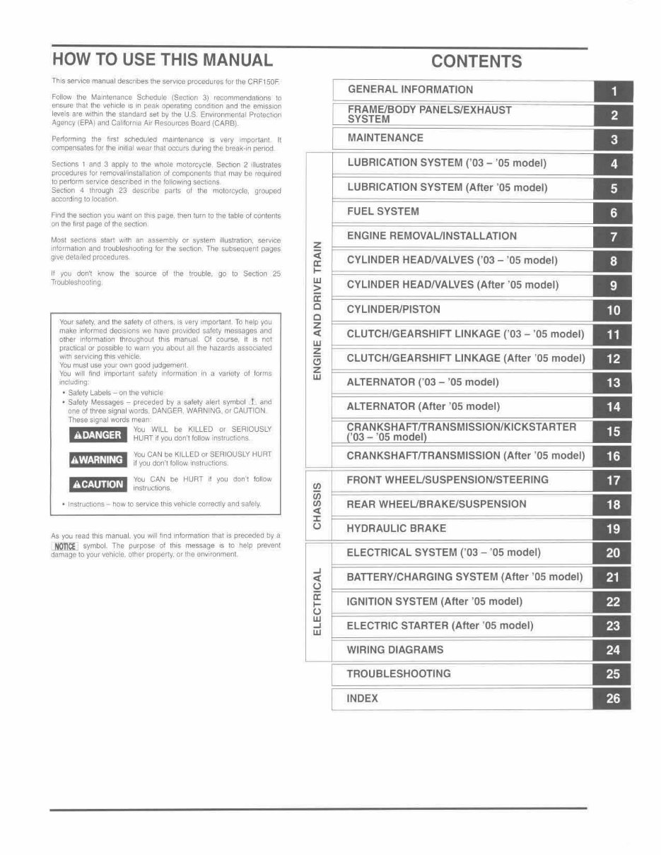
CONTENTS
GENERAL INFORMATION
MAINTENANCE
LUBRICATION SYSTEM (' 03 -' 05 model)
LUBRICATION SYSTEM (After '05 model)
FUEL SYSTEM
ENGINE REMOVAUINSTALLATION
CYLINDER HEADNALVES (' 03 - '05 model)
CYLINDER HEADNALVES (After '05 model)
CYLINDER/PISTON
CLUTCH/GEARSHIFT LINKAGE ('03 - '05 model)
CLUTCH/GEARSHIFT LINKAGE (After '05 model)
ALTERNATOR ('03 - '05 model)
ALTERNATOR (After ' 05 model)
CRANKSHAFTfTRANSMISSION (After '05 model)
FRONT WHEEUSUSPENSIONJSTEERING
REAR WHEEUBRAKEISUSPENSION
HYDRAULIC BRAKE
ELECTRICAL SYSTEM (' 03 -' 05 model)
BATTERY/CHARGING SYSTEM (After ' 05 model)
IGNITION SYSTEM (After '05 model)
ELECTRIC STARTER (After '05 model)
WIRING DIAGRAMS
TROUBLESHOOTING
INDEX
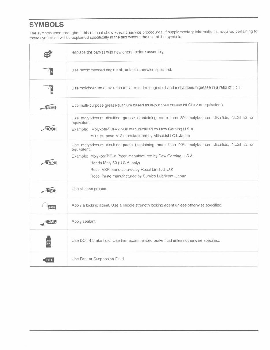
SYMBOLS
The symbols used throughout this manual show specific service procedures. If supplementary information is required pertaining to
these symbols, it will be explained specifically in the text without the use of the symbols.
tt
r-
,
I-
7J
~--..
I
I Replace the part(s) with new one(s) before assembly.
-,
t U,e ,ecommeoded e09ioe oil, oole" olhelWi,e ,pecilied,
Use molybdenum oil solution (mixture of the engine oil and molybdenum grease in a ratio of 1 : 1).
Use mUlti-purpose grease (lithium based multi-purpose grease NLGI #2 or equivalent).
-
-+ -
Use molybdenum disulfide grease (containing more than 3% molybdenum disulfide, NLGI #2 or
equivalent.
Example: Molykote® BR-2 plus manufactured by Dow Corning U.S.A.
Multi-purpose M-2 manufactured by Milsubishi Oil, Japan
---
Use molybdenum disulfide paste (containing more than 40% molybdenum disulfide. NLGI #2 or
equivalent.
Example: Molykote® G-n Paste manufactured by Dow Corning U.S.A.
Honda Moly 60 (U,S.A. only)
Roeol ASP manufactured by Roeol Limited. U.K.
Roeol Paste manufactured by Sumico Lubricant. Japan
Use s il icone grease,
Apply a locking agent. Use a middle strength locking agent unless otherwise specified.
-
Apply sealant.
Use DOT 4 brake fluid. Use the recommended brake fluid unless otherwise specified.
-
Use Fork or Suspension Fluid.
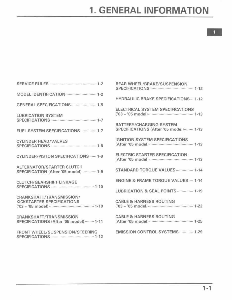
1. GENERAL INFORMATION
SERVICE RULES · .. ·············· .. ······················1-2
MODEL IDENTIFICATION··························· 1-2
GENERAL SPECIFICATIONS ...................... 1-5
LUBRICATION SYSTEM
SPECiFiCATiONS···································· ···1-7
FUEL SYSTEM SPECIFICATIONS·············· 1-7
CYLINDER HEADIV ALVES
SPECiFiCATIONS···························· ···········1-8
CYLINDER/PISTON SPECIFICATIONS ...... 1-9
ALTERNATOR/STARTER CLUTCH
SPECIFICATION (After '05 model) ············1-9
CLUTCH/GEARSHIFT LINKAGE
SPECiFiCATIONS································ ·····1-10
CRANKSHAFT/TRANSMISSION/
KICKSTARTER SPECIFICATIONS
('03 - '05 model) ·······································1-10
CRANKSHAFT/TRANSMISSION
SPECIFICATIONS (After '05 model) ········1-11
FRONT WHEEL/SUSPENSION/STEERING
SPECIFICATIONS······································ 1- 12
REAR WHEEL/BRAKE/SUSPENSION
SPECIFICATIONS ..................................... 1-12
HYDRAULIC BRAKE SPECIFICATIONS··· 1-12
ELECTRICAL SYSTEM SPECIFICATIONS
('03 - '05 model) ....................................... 1-13
BATTERY/CHARGING SYSTEM
SPECIFICATIONS (After '05 model)········ 1-13
IGNITION SYSTEM SPECIFICATIONS
(After '05 model) ······································1-13
ELECTRIC STARTER SPECIFICATION
(After '05 model) ······································1-13
STANDARD TORQUE VALUES··············· 1-14
ENGINE & FRAME TORQUE VALUES···· 1-14
LUBRICATION & SEAL POINTS ··············1-19
CABLE & HARNESS ROUTING
('03 - '05 model)······································· 1-22
CABLE & HARNESS ROUTING
(After '05 model) ······································1-25
EMISSION CONTROL SYSTEMS ............ 1-29
1-1
GENERAL INFORMATION
SERVICE RULES
1. Use genuine Honda or Honda- recommended parts and lubricants or their equivalents. Parts that don't meet Honda's
design specifications may cause damage to the mo torcycl e.
2. Use the special tools designed for this pr oduct to avoid damage and incorrect assembly.
3. Use only metric tools when servicing the motorcycle. Metric bolts, nuts and screws are not interchangeable with
English fasteners.
4. Inslall new gaskets, O-rings, cOlier pins, and lock plates when reassembling.
5. When tightening bolts or nuts, begin with the l arger diamete r or inner bolt first. Then lighten to the specified torque
diagonally in incremental steps unless a particular sequence is specified.
6. Clean parts in cleaning solvent upon disassembly. Lubric ate any sliding surfaces before reassembly.
7. After reassembly. check all parts f or proper installat ion and operation.
S. Route all electrical wires as shown in the Cable and Harness Routing (page 1-22).
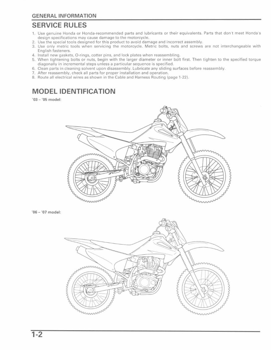
MODEL IDENTIFICATION
'03 - '05 model :
'06 - '07 model :
1-2
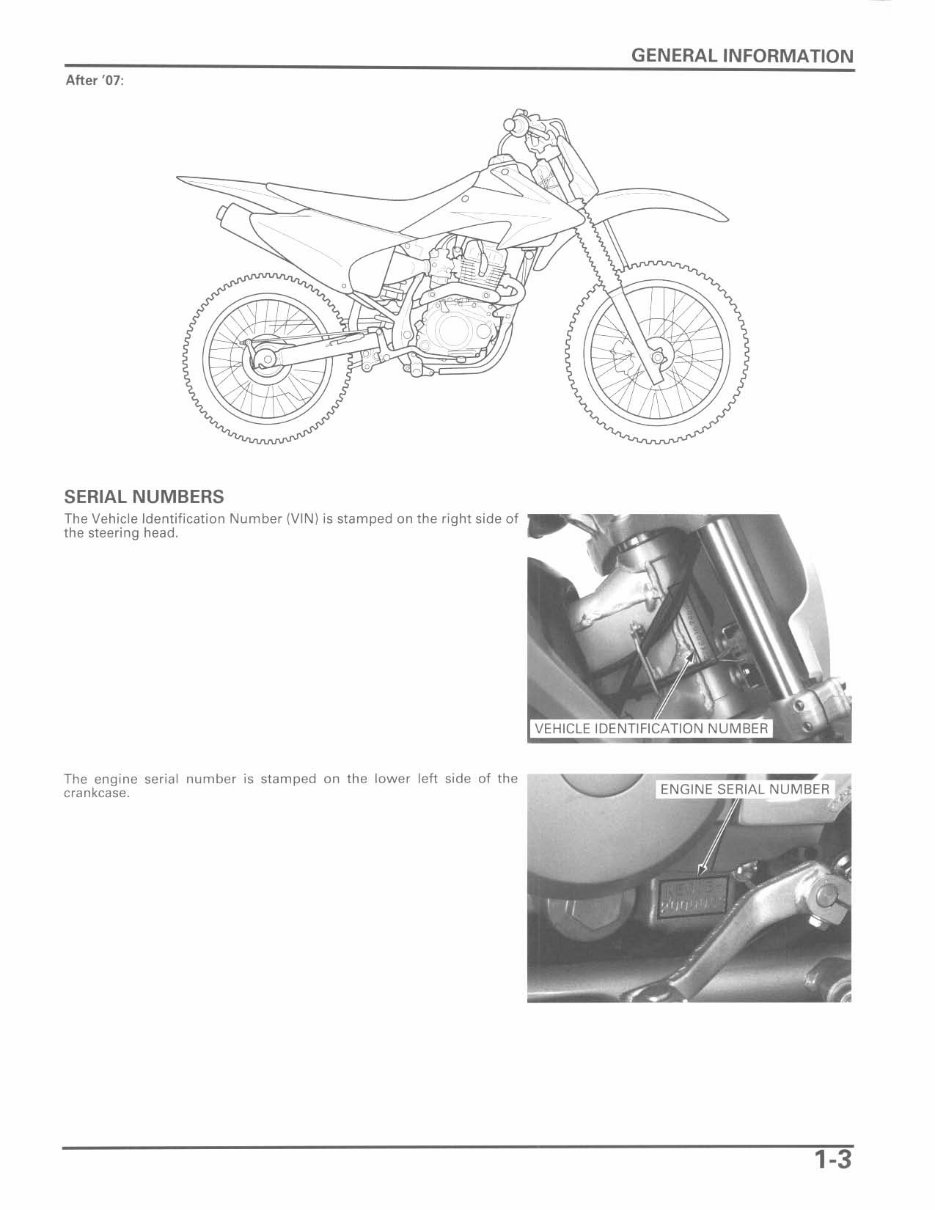
After ' 07 :
SERIAL NUMBERS
The Vehicle Identification Number {VIN} is stamped on the right side of
the steering head.
The engine seria l number is st amped on the lower left side of the
crankcase.
GENERAL INFORMATION
1-3
GENERAL INFORMATION
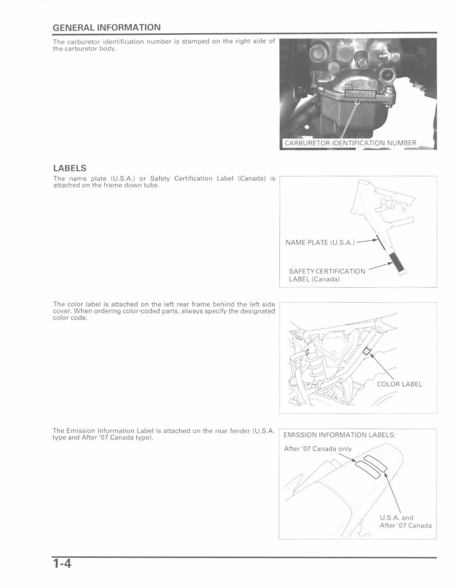
The carbure tor identification number is stamped on the right side of
the carburetor body.
LABELS
The name plate (U.S.A.) or Safety Certification Label (Canada) is - -
attached on the frame down tube.
r~
The color label is attached on the left rear frame behind the left side
cover. When ordering color-coded parts, always specify the designated
color code.
I '
I
!
,
\
\ /-
NAME PLATE (U.S.A.) ~ -'.
c
SAFE1YCERTlFlCATION A
LABEL (Canada)
COLOR LABEL
The Emission Information Label is attached on the rear fender (U.S.A. 'EMISSION INFORMATION LABELS:
type and After '07 Canada type).
Aft" '07 Canada ~
/
U.S.A. and
/
After '07 Canada
1-4
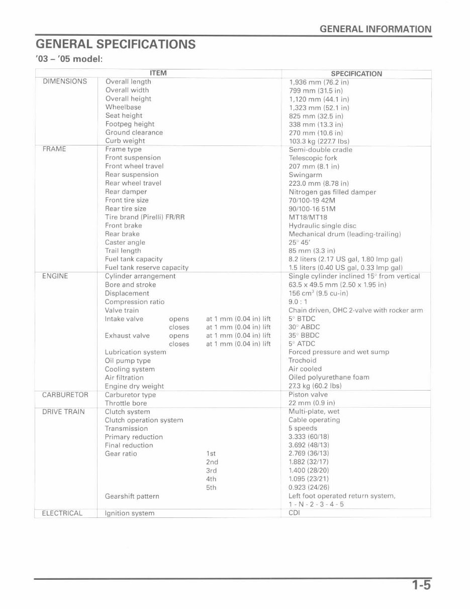
GENERAL SPECIFICATIONS
'03 - '05 model:
I DIMENSIONS
ITEM
Overall length
Overall width
Overall height
Wheelbase
Seat height
Footpeg height
Ground clearance
o _ _ _ f--,C~urb weight
FRAME Frame type
I ENGINE
CARBURETOR
DRIVE TRAIN
ELECTRICAL
Front suspension
Front wheel travel
Rear suspension
Rear wheel travel
Rear damper
Front tire size
Rear tire size
Tire brand (Pirelli) FR/RR
Front brake
Rear brake
Caster angle
Trail length
Fuel tank capacity
Fuel tank reserve capacity
Cylinder arrangement
Bore and stroke
Displacement
Compression ratio
Valve train
Intake valve
Exhaust valve
Lubrication system
Oil pump type
Cooling system
Air filtration
Engine dry weight
Carburetor type
Throttle bore
Clutch system
opens
closes
opens
closes
Clutch operation system
Transmission
Primary reduction
Final reduction
Gear ratio
I Gearshift pattern
1 Ignition system
at 1 mm (0.04 in) lift
at I mm (0.04 in) lift
at 1 mm (0.04 in) lift
at 1 mm (0.04 in) lift
,,,
2nd
3,d
4th
5th
GENERAL INFORMATION
SPECIFICATION
1,936 mm (76.2 in)
799 mm (31.5 in)
1,120 mm (44.1 in)
1,323 mm (52.1 in)
825 mm (32.5 in)
338 mm (13.3 in)
270 mm (10.6 in)
103.3 kg (227.7 Ibs)
Semi-double cradle
Telescopic fork
207 mm (8.1 in)
Swingarm
223.0 mm (8.78 in)
Nitrogen gas filled damper
70/100·1942M
90/100·1651M
MT18/MT18
Hydraulic single disc
Mechanical drum (leading-trailing)
25° 45'
85 mm (3.3 in)
8.2 liters (2.17 US gal, 1.80 Imp gal)
1.5 liters {0.40 US gal, 0.33 Imp gal}
Single cylinder inclined 15" from vertical
63.5 x 49.5 mm (2.50 x 1.95 in)
156 cm
3
(9.5 cu-in)
9.0: 1
Chain driven. OHC 2-valve with rocker arm
5° BTDC
30" ABDC
35° BBDC
5° ATDC
Forced pressure and wet sump
Trochoid
Air cooled
Oiled polyurethane foam
27.3 kg (60.2 Ibs)
-- Piston valve
22 mm (0.9 in)
Multi-plate, wet
Cable operating
5 speeds
3.333 (60/18)
3.692 (48/13)
2.769 (36/13)
1.882 (32/17)
1.400 (28/20)
1.095 (23/21)
0.923 (24/26)
Left foot operated return system.
l-N-2-3-4-5
COl
1-5
GENERAL INFORMATION
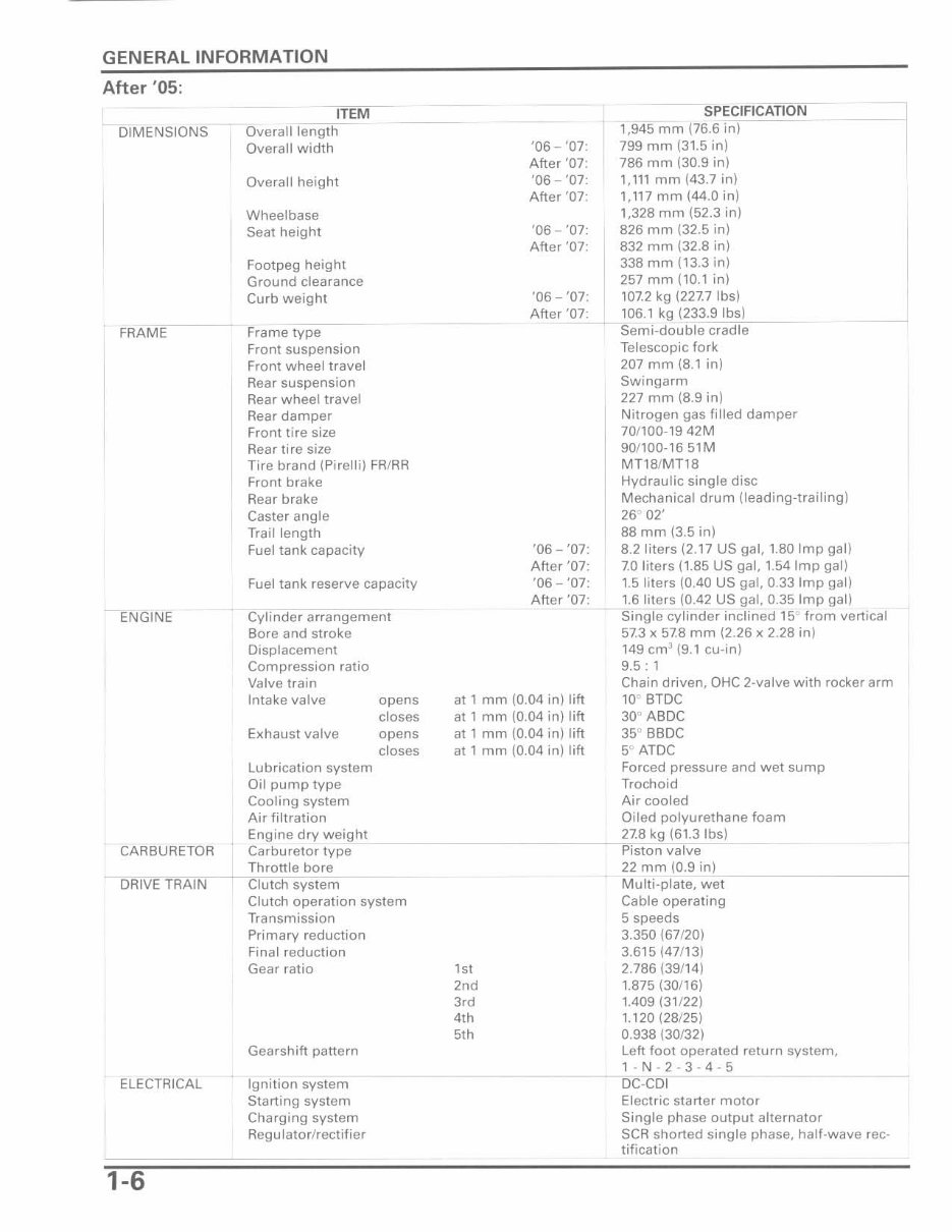
After '05:
DIMENSIONS
FRAME
ENGINE
CARBURETOR
ITEM
Overatllength
Overall width
Overall height
Wheelbase
Seat height
Footpeg height
Ground clearance
Curb weight
Frame type
Front suspension
Front wheel travel
Rear suspension
Rear whee l travel
Rear damper
Front tire size
Rear tire size
Tire brand (Pirelli) FR/RR
Front brake
Rear brake
Caster angle
Trail length
Fuel tank capacity
Fuel tank reserve capacity
Cylinder arrangement
Bore and stroke
Displacement
Compression ratio
Valve train
Intake valve opens
closes
Exhaust valve opens
lubrication syst em
Oil pump type
Cooling system
Air filtration
closes
Engine dry weight
Carburetor type
Throttle bore
DRIVE TR'''A''INCO-~-C;;I:C"~tch system
ELECTRICAL
1-6
Clutch ope r ation system
Transmission
Primary reduction
Final reduction
Gear ratio
Gearshift pattern
Ignition system
Starting system
Charging system
Reg u lato rlrect ifie r
'06 - '07:
After '07:
'06 - '07:
After '07:
'06 - '07:
After '07:
'06 - '07:
After '07:
SPECIFICATION
1,945 mm (76.6 in)
799 mm (31.5 in)
786 mm (30.9 in)
1, III mm (43.7 in)
1,117 mm (44.0 in)
1,328 mm (52.3 in)
826 mm (32.5 in)
832 mm (32.8 in)
338 mm (13.3 in)
257 mm (10.1 in)
107.2 kg (227.7 Ibs)
106.1 kg (233.9 Ibs) .
Semi-double cradle
Telescopic fork
207 mm (8.1 in)
Swingarm
227 mm (8.9 in)
Nitrogen gas filled damper
70/100-1942M
90/100-1651M
MT18/MT18
Hydraulic single disc
Mechanical drum (leading - trailing)
26° 02'
88 mm (3.5 in)
'06 - '07: 8.2 liters (2.17 US gal, 1.80 Imp gal)
After '07: 7.0 lit ers (1.85 US gal, 1.54 Imp gall
'06 - '07: 1.5 liters (OAO US gal, 0.33 Imp gal)
After _ 'O~7~'_~ '~.6~liters (0.42 US gal, 0.35 Imp gal)
Single cylinder inclined 15° f rom vertical
57.3 x 57.8 mm (2.26 x 2.28 in)
149 em' (9.1 cu-in)
9.5 : 1
at I mm (0.04 in) lift
at 1 mm (0.04 in) lift
at I mm (0.04 i n) lift
at 1 mm (0.04 in) lift
Chain driven, QHC 2·valve with rocker arm
10° BTDC
30 ABDC
35° BBDC
5° ATDC
,"
2,d
'cd
4th
5th
Forced pressure and wet sump
Trochoid
Air cooled
Oiled polyurethane foam
__ ~_2",7".8",kg (61.3 Ibs)
Piston valve
22 mm (0.9 in)
Multi·plate, wet
Cable operating
5 speeds
3.350 (67/20)
3.615 (47/13)
2.786 (39/14)
1.875 (30116)
1.409 (31/22)
1.120 (28/25)
0.938 (30/32)
Left foot operated return system,
1- N·2·3·4·5
DC·CDI
Electric starter motor
Single phase output alternator
seR shorted single phase, half·wave rec-
tification
GENERAL INFORMATION
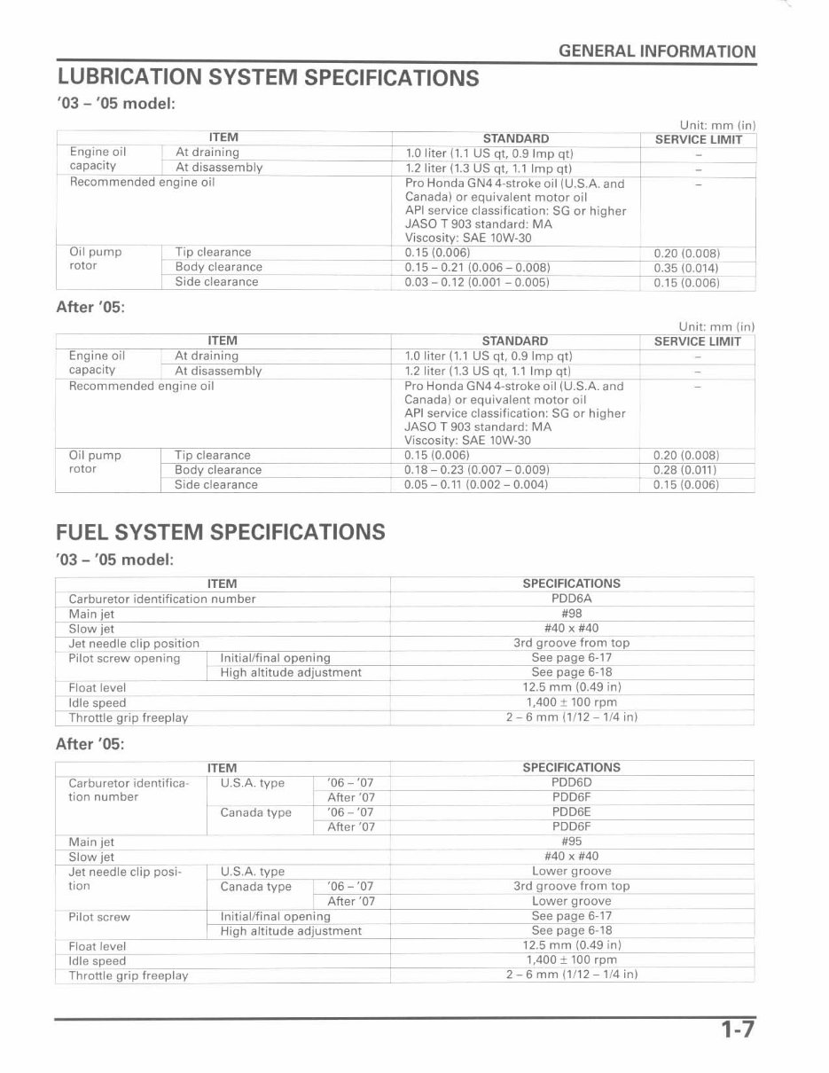
LUBRICATION SYSTEM SPECIFICATIONS
' 03 - '05 model:
ITEM
Engine oil At draining
capacity At disassembly
Recommended engine oil
Oil pump
rotor
Tip clearance
Body clearance
Side clearance
Unit: mm (in)
STANDARD ~ ERVICE LIMIT
-====~1.0 liter (1.1 US qt, 0.9 Imp qt) _
1.2 liter (1.3 US qt, 1.1 Imp qt) - ---
----+-~P~ro Honda GN4 4-stroke oil (U.S.A. and _
Canada) or equivalent motor oil
1
API service classification: SG or higher
JASO T 903 standard: MA
Viscosity: SAE lOW-30 __ ~~=
0.15 (0.006) _____ 0.20 (0.008)
0.15 0.21 {0.006 O.OOB} 0.35 (0.014)
0.03 0.12 (0.001 0.005) 0.15 (O.006)
After '05:
ITEM
Engine oil At draining
capacity At disassembly
Recommended engine oil
Unit: mm (in)
STANDARD ___ + -"S ER VICE LIMIT I
1.0 liter (1.1 US qt, 0.9 Imp qt) ~
1.2 liter (1.3 US qt. 1.1,~lm~p~q~t)~~;:;:;:::==-
Pro Honda GN44-stroke oil (U.S.A. and 1
Canada) or equivalent motor oil
API service classification: SG or higher
JASO T 903 standard: MA
Viscosity: SAE lOW-30
Oil pump
rotor
Tip clearance
Body clearance
Side clearance
0.15 (0.006) 0.20 (0.008)
__ ~",0.,c.'8~- 0.23 (0.007 - 0.0'''09'''1----~---i OC;.2fii8iIOiC.iCo,i'i,i'-1
0.05 0.11 (0.002 - 0.004) 0.15 (0.006)
FUEL SYSTEM SPECIFICATIONS
'03 - '05 model :
ITEM
Carburetor identification number
Main jet
Slow jet
Jet needle clip position
Pilot screw opening Initial/final opening
Float level
Idle speed
Throttle grip freeplay
After ' 05:
I High altitude adjustment
ITEM
SPECIFICATIONS
PDD6A
#98
#40 x #40
3rd groove from top
See page 6·17
Seepage6·18
12.5 mm (O.49 in)
1,400 ± 100 rpm
2 - 6 mm (1/12 -1/4 in)
SPE CIFICATIONS
~~ ________________ ~PDD6D
+~'"-c~-- PDD6F
I Carburetor identifica· U.S.A. type '06 '07
tion number After '07
t
Canada type
Main jet
Slow jet
Jet needle clip posi· U.S.A. type
·06 ·07
After '07
PDD6E
PDD6F
#95
#40 x #40
Lower groove
tion Canada type
I
'06 '07 3rd groove from t~o2P ,-______ _
After '07 Lower groove
___ -iS~'~'~page 6·17
See page 6·18
Pilot screw Initial/final opening
High altitude adjustment
Float level 12.5 mm (0.49 in)
t
Idle speed
,
Throttle grip freeplay
1,400 ± 100 rpm
2 - 6 mm (1/12 - 1/4 in)
1-7
You're Reading a Preview
What's Included?
Fast Download Speeds
Online & Offline Access
Access PDF Contents & Bookmarks
Full Search Facility
Print one or all pages of your manual
$31.99
Viewed 77 Times Today


Secure transaction
What's Included?
Fast Download Speeds
Online & Offline Access
Access PDF Contents & Bookmarks
Full Search Facility
Print one or all pages of your manual
$31.99
Get your hands on the comprehensive repair manual for the 2003-2013 Honda CRF150F four-stroke bike. This manual covers everything from complete tear down and rebuild, to pictures and part diagrams, torque specs, maintenance, troubleshooting, and more. With 403 pages, it's a valuable resource for both professional mechanics and DIY enthusiasts.
This manual features clickable chapters and is searchable, making it easy to find the information you need. There are no restrictions on printing or saving/burning to disc, providing you with convenient access to the manual.
- Complete tear down and rebuild
- Pictures and part diagrams
- Torque specs
- Maintenance procedures
- Troubleshooting guidance
- Clickable chapters
- Searchable content
- No restrictions on printing or saving/burning to disc


