

1976-1990 Honda CG125 CG 125 Service & Repair Manual
What's Included?
Fast Download Speeds
Online & Offline Access
Access PDF Contents & Bookmarks
Full Search Facility
Print one or all pages of your manual

Honda
CG125
Owners
Workshop
Manual
by Pete Shoemark
with an additional Chapter on the 1985 on models
by Jeremy Churchill
Models covered
CG125. 124cc. June 1976 to May 1978
CG125K1. 124cc. May 1978 to March 1981
CG125-B. 124cc. March 1981 to March 1982
CG125-C. 124cc. March 1982 to November 1984
CG125-E. 124cc. November 1984 to April 1985
CG125(BR)-E/F. 124cc. April 1985 to April 1988
CG125(BR)-J. 124cc. April 1988 to September 1991
CG125(BR)-K. 124cc. September 1991 on
ISBN 1 85010 918 4
© Haynes Publishing 1994
All rights reserved. No part of this book may be reproduced or transmitted in
any form or by any means, electronic or mechanical, including photocopying,
recording or by any information storage or retrieval system, without permission
in writing from the copyright holder.
Printed in the USA (433-4T9)
Haynes Publishing
Sparkford Nr Yeovil
Somerset BA22 7JJ England
Haynes Publications, Inc
861 Lawrence Drive
Newbury Park
California 91320 USA
British Library CataloGuing in Publication Data
A catalogue record for this book is available
from the British Library
~

Acknowledgements
Our thanks are due to APS Motorcycles of Wells (formerly
Fran Ridewood & Co), Paul Branson Motorcycles of Yeovil, and
CSM of Taunton, who supplied the machines featured in this
manual.
We would also like to thank the Avon Rubber Company, who
kindly supplied information and technical assistance on tyre
fitting; NGK Spark Plugs (UK) Ltd for information on spark plug
maintenance and electrode conditions and Renold Limited for
advice on chain care and renewal.
About this manual
The author of this manual has the conviction that the only
way in which a meaningful and easy to follow text can be
written is first to do the work himself, under conditions similar
to those found in the average household. As a result, the hands
seen in the photographs are those of the author. Even the
machines are not new: examples that have covered a consider-
able mileage were selected so that the conditions encountered
would be typical of those found by the average owner.
Unless specially mentioned, and therefore considered
essential, Honda service tools have not been used. There is
invariably some alternative means of slackening or removing
some vital component when service tools are not available and
risk of damage has to be avoided at all costs.
Each of the six Chapters is divided into numbered Sections.
Within the Sections are numbered paragraphs. In consequence,
cross reference throughout this manual is both straightforward
and logical. When a reference is made 'See Section 5.12' it
means Section 5, paragraph 12 in the same Chapter. If another
Chapter were meant, the text would read 'See Chapter 2,
Section 5.12'. All photographs are captioned with a
Section/paragraph number to which they refer and are always
relevant to the Chapter text adjacent.
Figure numbers (usually line illustrations) appear in
numerical order, within a given Chapter. Fig. 1.1 therefore refers
to the first figure in Chapter 1. Left-hand and right-hand
descriptions of the machines and their component parts refer to
the right and left of a given machine when the rider is seated
normally.
Motorcycle manufacturers continually make changes to
specifications and recommendations, and these, when notified,
are incorporated into our manuals at the earliest opportunity.
We take great pride in the accuracy of information given in
this manual, but motorcycle manufacturers make alterations and
design changes during the production run of a particular
motorcycle of which they do not inform us. No liability can be
accepted by the authors or publishers for loss, damage or injury
caused by any errors in, or omissions from, the information given.

Contents
Acknowledgements
About this manual
Introduction to the Honda CG125
Model dimensions and weight
Ordering spare parts
Safety first!
Routine maintenance
Quick glance maintenance adjustments and capacities
Recommended lubricants
Working conditions and tools
Chapter 1 Engine, clutch and gearbox
Chapter 2 Fuel system and lubrication
Chapter 3 Ignition system
Chapter 4 Frame and forks
Chapter 5 Wheels, brakes and tyres
Chapter 6 Electrical system
Chapter 7 The 1985 on models
Wiring diagrams
Conversion factors
Index
Page
2
2
5
5
6
7
8
13
13
/
15
52
60
67
80
93
107
103, 124
125
126
I

The Honda CG125 model
The Honda CG125-C model

Introduction to the Honda CG125
The CG125 model first appeared in the UK in June 1976. It
can be regarded in many ways as a utility version of the popular
CB1 25 with which it shares many features. The basic difference
between the two models is the CG125's use of pushrod
operated overhead valves in place of the more popular overhead
camshaft arrangement. The unit provides surprisingly brisk
performance coupled with good fuel economy. The machine in
general is functional and sensibly equipped, and does not suffer
the surfeit of gadgetry so often found on its contemporaries. Its
inherent simplicity makes it an ideal learner's or commuter's
mount, both in terms of ease of riding and in its ease of
maintenance. A noteworthy feature is the adoption of a full rear
chain enclosure. Although this is by no means a new idea,
having appeared and disappeared many times over the years
with the changing dictates of fashion, it is, nevertheless, an
eminently sensible feature, greatly extending chain life.
Despite remaining basically unchanged, the CG125 has
received several modifications and has been altered slightly in
appearance to keep up with its rivals. Five distinct versions have
appeared, with differences of varying significance, which are
identified (where applicable) in this Manual by their Honda
model code suffixes. Identification details, as available, are
given below with the approximate dates of import; note that the
latter need not necessarily coincide with the machine's date of
registration.
The CG125 model (no identifying suffix) has the frame
numbers CG125-1023061 to 1111090. Engine numbers are
not available. Identified by its shrouded, external spring, front
forks, this model Was imported from June 1976 to May 1978.
The CG125K1 model has the frame numbers
CG125-1114636 to 1162518. Engine numbers not available.
It differed most noticeably from the CG125 model in having
front forks with internal springs and exposed stanchions, and
was imported from May 1978 to March 1981.
The CG125-B model has the frame numbers
CG125-1202755 to 1223689; its engine numbers start at
CG125E-1374586. It can be distinguished from the K1 model
only by its different paintwork and graphics and was imported
from March 1981 to March 1982.
The CG125-C model has the frame numbers
CG125-1272831 to 1286692; its engine numbers start at
CG125E-1513928 on. Fitted with revised tail lamp, flashing
indicator lamps, handlebar switches and the usual detail
changes to paintwork and graphics. This model is also fitted
with a higher compression engine and the (T)PFC carburettor
for greater fuel economy. Note also that the ignition switch is
combined in a new warning lamp cluster, mounted next to the
speedometer. Imported from March 1982 to November 1984.
The CG125-E model has the frame number
CG 125-1288790 to 1293380 and the engine numbers
CG125E-1689761 to 1694851. Identical to the C model
except for detail changes to the graphics, this model was
imported from November 1984 to April 1985.
All the aforementioned models are of Japanese
manufacture and are covered in Chapters 1 to 6. Later models
were manufactured in Brazil and known as the CG125(BR)
models; refer to Chapter 7 for further information.
Model dimensions and weight
Overall length
Overall width
Overall height
Wheelbase
Seat height
Ground clearance
Dry weight
1840 m m (72.4 in)
735 m m (28.9 in)
1025 mm (40.4 in)
1200 m m (47.2 in)
755 m m (29.7 in)
135 m m (5.3 in)
95 kg (209 Ib)

Ordering spare parts
*
When ordering spare parts for the CG125 models, it is
advisable to deal direct with an official Honda agent, who will
be able to supply many of the items required ex-stock. It is
advisable to get acquainted with the local Honda agent, and to
rely on his advice when purchasing spares. He is in a better
position to specify exactly the parts required and to identify the
relevant spare part numbers so that there is less chance of the
wrong part being supplied by the manufacturer due to a vague
or incomplete description.
When ordering spares, always quote the frame and engine
numbers in full, together with any prefixes or suffixes in the
form of letters. The frame number is found stamped on the
right-hand side of the steering head, in line with the forks. The
engine number is stamped on the left-hand side of the
crankcase, immediately behind the oil strainer cap.
Use only parts of genuine Honda manufacture. A few
pattern parts are available, sometimes at a cheaper price, but
there is no guarantee that they will give such good service as
the originals they replace. Retain any worn or broken parts until
the replacements have been obtained; they are sometimes
needed as a pattern to help identify the correct replacement
when design changes have been made during a production run.
Some of the more expendable parts such as spark plugs,
bulbs, tyres, oils and greases etc., can be obtained from
accessory shops and motor factors, who have convenient
opening hours and can often be found not far from home. It is
also possible to obtain them on a Mail Order basis from a
number of specialists who advertise regularly in the motorcycle
magazines.
Frame number location Engine number location

Safety first!
Professional motor mechanics are trained in safe working
procedures. However enthusiastic you may be about getting on
with the job in hand, do take the time to ensure that your safety
is not put at risk. A moments lack of attention can result in an
accident, as can failure to observe certain elementary
precautions.
There will always be new ways of having accidents, and the
following points do not pretend to be a comprehensive list of all
dangers; they are intended rather to make you aware of the
risks and to encourage a safety-conscious approach to all work
you carry out on your vehicle.
Essential DOs and DON'Ts
DON'T start the engine without first ascertaining that the
transmission is in neutral.
DON'T suddenly remove the filler cap from a hot cooling
system - cover it with a cloth and release the pressure gradually
first, or you may get scalded by escaping coolant.
DON'T attempt to drain oil until you are sure it has cooled
sufficiently to avoid scalding you.
DON'T grasp any part of the engine, exhaust or silencer without
first ascertaining that it is sufficiently cool to avoid burning you.
DON'T allow brake fluid or antifreeze to contact the machine's
paintwork or plastic components.
DON'T syphon toxic liquids such as fuel, brake fluid or
antifreeze by mouth, or allow them to remain on your skin.
DON'T inhale dust - it may be injurious to health (see Asbestos
heading).
DON'T allow any spilt oil or grease to remain on the floor —
wipe it up straight away, before someone slips on it.
DON'T use ill-fitting spanners or other tools which may slip and
cause injury.
DON'T attempt to lift a heavy component which may be
beyond your capability - get assistance.
DON'T rush to finish a job, or take unverified short cuts.
DON'T allow children or animals in or around an unattended
vehicle.
DON'T inflate a tyre to a pressure above the recommended
maximum. Apart from overstressing the carcase and wheel rim,
in extreme cases the tyre may blow off forcibly.
DO ensure that the machine is supported securely at all times.
This is especially important when the machine is blocked up to
aid wheel or fork removal.
DO take care when attempting to slacken a stubborn nut or
bolt. It is generally better to pull on a spanner, rather than push,
so that if slippage occurs you fall away from the machine rather
than on to it.
DO wear eye protection when using power tools such as drill,
sander, bench grinder etc.
DO use a barrier cream on your hands prior to undertaking dirty
jobs — it will protect your skin from infection as well as making
the dirt easier to remove afterwards; but make sure your hands
aren't left slippery. Note that long-term contact with used
engine oil can be a health hazard.
DO keep loose clothing (cuffs, tie etc) and long hair well out of
the way of moving mechanical parts.
DO remove rings, wristwatch etc, before working on the vehicle
- especially the electrical system.
DO keep your work area tidy - it is only too easy to fall over
articles left lying around.
DO exercise caution when compressing springs for removal or
installation. Ensure that the tension is applied and released in a
controlled manner, using suitable tools which preclude the
possibility of the spring escaping violently.
DO ensure that any lifting tackle used has a safe working load
rating adequate for the job.
DO get someone to check periodically that all is well, when
working alone on the vehicle.
DO carry out work in a logical sequence and check that
everything is correctly assembled and tightened afterwards.
DO remember that your vehicle's safety affects that of yourself
and others. If in doubt on any point, get specialist advice.
IF, in spite of following these precautions, you are unfortunate
enough to injure yourself, seek medical attention as soon as
possible.
Asbestos
Certain friction, insulating, sealing, and other products -
such as brake linings, clutch linings, gaskets, etc - contain
asbestos. Extreme care must be taken to avoid inhalation of
dust from such products since it is hazardous to health. If in
doubt, assume that they do contain asbestos.
Fire
Remember at all times that petrol (gasoline) is highly
flammable. Never smoke, or have any kind of naked flame
around, when working on the vehicle. But the risk does not end
there - a spark caused by an electrical short-circuit, by two
metal surfaces contacting each other, by careless use of tools,
or even by static electricity built up in your body under certain
conditions, can ignite petrol vapour, which in a confined space
is highly explosive.
Always disconnect the battery earth (ground) terminal
before working on any part of the fuel or electrical system, and
never risk spilling fuel on to a hot engine or exhaust.
It is recommended that a fire extinguisher of a type suitable
for fuel and electrical fires is kept handy in the garage or
workplace at all times. Never try to extinguish a fuel or electrical
fire with water.
Note: Any reference to a 'torch' appearing in this manual
should always be taken to mean a hand-held battery-operated
electric lamp or flashlight. It does not mean a welding/gas torch
or blowlamp.
Fumes
Certain fumes are highly toxic and can quickly cause
unconsciousness and even death if inhaled to any extent. Petrol
(gasoline) vapour comes into this category, as do the vapours
from certain solvents such as trichloroethylene. Any draining or
pouring of such volatile fluids should be done in a well
ventilated area.
When using cleaning fluids and solvents, read the instruc-
tions carefully. Never use materials from unmarked containers -
they may give off poisonous vapours.
Never run the engine of a motor vehicle in an enclosed
space such as a garage. Exhaust fumes contain carbon mon-
oxide which is extremely poisonous; if you need to run the
engine, always do so in the open air or at least have the rear of
the vehicle outside the workplace.
The battery
Never cause a spark, or allow a naked light, near the
vehicle's battery. It will normally be giving off a certain amount
of hydrogen gas, which is highly explosive.
Always disconnect the battery earth (ground) terminal
before working on the fuel or electrical systems.
If possible, loosen the filler plugs or cover when charging
the battery from an external source. Do not charge at an
excessive rate or the battery may burst.
Take care when topping up and when carrying the battery.
The acid electrolyte, even when diluted, is very corrosive and
should not be allowed to contact the eyes or skin.
If you ever need to prepare electrolyte yourself, always add
the acid slowly to the water, and never the other way round.
Protect against splashes by wearing rubber gloves and goggles.
Mains electricity and electrical equipment
When using an electric power tool, inspection light etc,
always ensure that the appliance is correctly connected to its
plug and that, where necessary, it is properly earthed
(grounded). Do not use such appliances in damp conditions
and, again, beware of creating a spark or applying excessive
heat in the vicinity of fuel or fuel vapour. Also ensure that the
appliances meet the relevant national safety standards.
Ignition HT voltage
A severe electric shock can result from touching certain
parts of the ignition system, such as Ihe HT leads, when the
engine is running or being cranked, particularly if components
are damp or the insulation is defective. Where an electronic
ignition system is fitted, the HT voltage is much higher and
could prove fatal.

Routine maintenance
Refer to Chapter 7 for information relating to the 1985 on Brazilian models
Introduction
Periodic routine maintenance is a continuous process that
commences immediately the machine is used. It must be
carried out at specified mileage recordings, or on a calendar
basis if the machine is not used frequently, whichever is the
sooner. Maintenance should be regarded as an insurance policy,
to help keep the machine in the peak of condition and to ensure
long, trouble-free service. It has the additional benefit of giving
early warning of any faults that may develop and will act as a
regular safety check, to the obvious advantage of both rider and
machine alike.
The various maintenance tasks are described under their
respective mileage and calendar headings. Accompanying
diagrams are provided, where necessary. It should be remem-
bered that the interval between the various maintenance tasks
serves only as a guide. As the machine gets older or is used
under particularly adverse conditions, it would be advisable to
reduce the period between each check.
For ease of reference each service operation is described in
detail under the relevant heading. However, if further general
information is required, it can be found within the manual under
the pertinent section heading in the relevant Chapter.
In order that the routine maintenance tasks are carried out
with as much ease as possible, it is essential that a good selec-
tion of general workshop tools is available.
Included in the kit must be a range of metric ring or com-
bination spanners, a selection of crosshead screwdrivers and at
least one pair of circlip pliers.
Additionally, owing to the extreme tightness of most casing
screws on Japanese machines, an impact screwdriver, together
with a choice of large and small crosshead screw bits, is
absolutely indispensable. This is particularly so if the engine has
not been dismantled since leaving the factory.
prevent the risk of unexpected failure of any component while
riding the machine and, with experience, can be reduced to a
simple checklist which will only take a few moments to
complete. For those owners who are not inclined to check all
items with such frequency, it is suggested that the best course
is to carry out the checks in the form of a service which can be
undertaken each week or before any long journey. It is essential
that all items are checked and serviced with reasonable
frequency.
/ Check the engine oil level
With the machine standing upright on its centre stand on
level ground, start the engine and allow it to idle for a few
seconds so that the oil can circulate, then stop the engine. Wait
one or two minutes for the level to settle and unscrew the
dipstick/filler plug from the rear of the crankcase right-hand
cover. Wipe it clean and insert it into the filler orifice; do not
screw it in, but allow it to rest. Withdraw the dipstick; the oil
level should be between the maximum and minimum level lines,
ie in the cross-hatched area.
If topping up is necessary use only good quality
SAE10W/40 engine oil of the specified type. Do not allow the
level to rise above the top of the cross-hatched area on the
dipstick, and never use the machine if the level is found to be in
the plain area below the cross-hatching; top up immediately.
Tighten the dipstick securely and wash off any spilt oil.
2 Check the fuel level
Checking the petrol level may seem obvious, but it is all too
easy to forget. Ensure that you have enough petrol to complete
your journey, or at least to get you to the nearest petrol station.
Daily (pre-ride check)
It is recommended that the following items are checked
whenever the machine is about to be used. This is important to
3 Check the brakes
Check the front and rear brakes work effectively and
without binding. Ensure that the cable or rod linkage is
lubricated and properly adjusted.
Rest dipstick in position to obtain correct reading Dipstick shows allowable oil level range
Routine maintenance
4
Check the tyre pressures and tread wear
Check the tyre pressures with a gauge that is known to be
accurate. It is worthwhile purchasing a pocket gauge for this
purpose because the gauges on garage forecourt airlines are
notoriously inaccurate. The pressures, which should be checked
with the tyres cold, are specified at the end of Routine
maintenance and in Chapter 5.
At the same time as the tyre pressures are checked,
examine the tyres themselves. Check them for damage,
especially splitting of the sidewalls. Remove any small stones or
other road debris caught between the treads. When checking
the tyres for damage, they should be examined for tread depth
in view of both the legal and safety aspects. It is vital to keep
the tread depth within the UK legal limits of 1 mm of depth over
three-quarters of the tread breadth around the entire circumfer-
ence with no bald patches. Many riders, however, consider
nearer 2 mm to be the limit for secure roadholding, traction, and
braking, especially in adverse weather conditions, and it should
be noted that Honda recommend minimum tread depths of 1.5
mm (0.06 in) for the front tyre and 2.0 mm (0.08 in) for the rear;
these measurements to be taken at the centre of the tread.
Renew any tyre that is found to be damaged or excessively
worn.
5 Safety check
Check that the front and rear suspension is operating
correctly, that the chain is lubricated and adjusted correctly and
that the battery is in good condition. Check the throttle and
clutch cables and levers, the gear lever and the footrests and
stand to ensure that they are adjusted correctly, functioning
correctly, and that all nuts and bolts are securely fastened.
6 Legal check
Check that all lights, turn signals, horn and speedometer are
working correctly to make sure that the machine complies with
all legal requirements in this respect. Check also that the
headlamp is correctly aimed to comply with local legislation.
Monthly or every 600 miles (1000 km)
/ Check the battery
The battery should be checked regularly to ensure that the
electrolyte level is maintained between the level lines on the
casing, that the terminals are clean and securely fastened and
that the vent tube is correctly routed and free from blockages.
Refer to Chapter 6.5 for details.
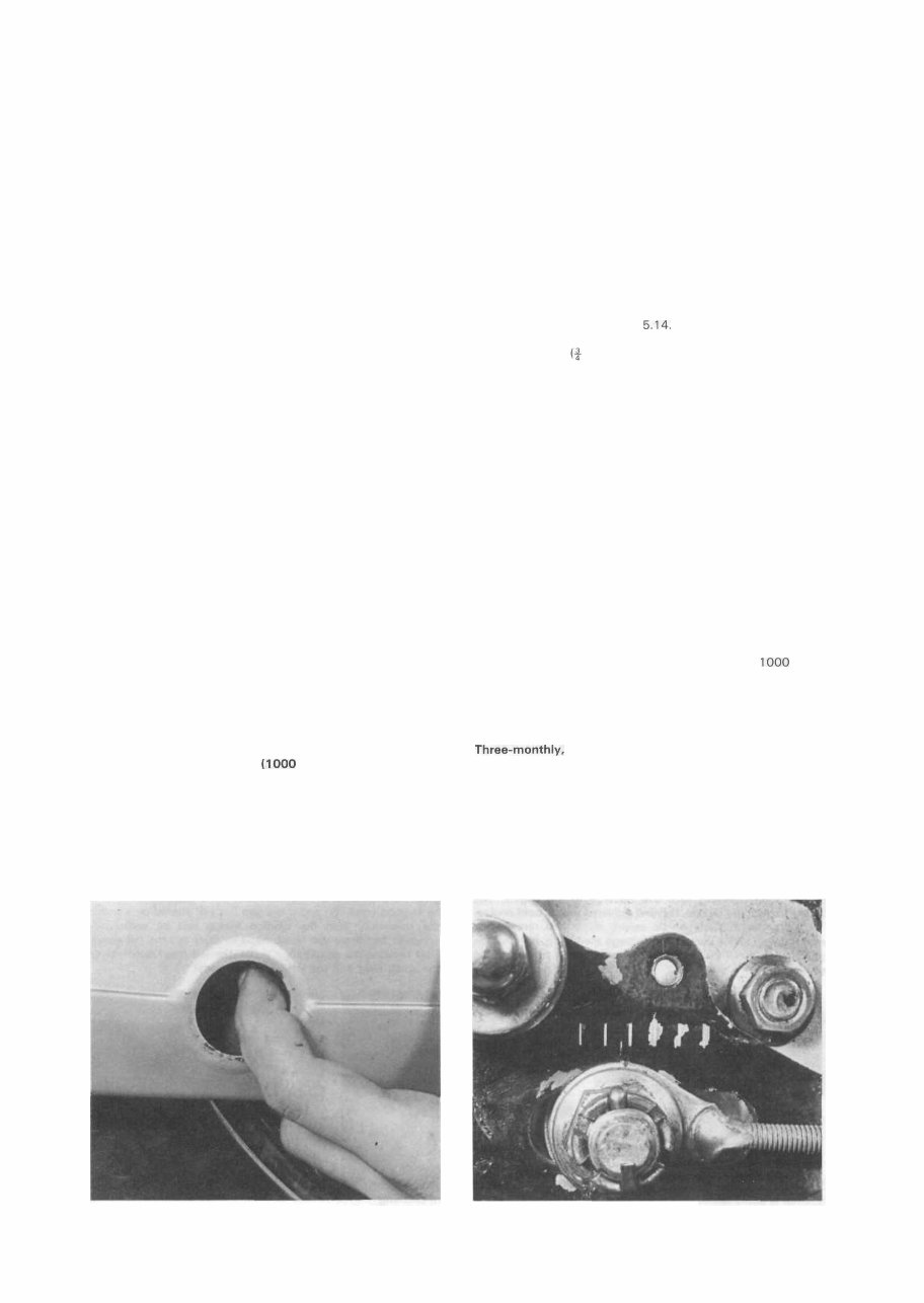
2 Check the final drive chain
Despite its full enclosure, the final drive chain requires
regular attention to ensure maximum chain life. Remove the
rubber plug from the chaincase inspection aperture to check the
tension and carry out temporary lubrication. The best lubricant
is commercial chain lubricant, contained in an aerosol can;
engine oil or gear oil are better than nothing but are flung off too
quickly to be of any real use. Best of all are the special chain
greases described in Chapter 5.14.
Adjust the chain after lubrication, so that there is approx-
imately 20 mm (|- in) slack in the middle of the lower run.
Always check with the chain at the tightest point as a chain
rarely wears evenly during service.
Adjustment is accomplished after placing the machine on
the centre stand and slackening the spindle nut, so that the
wheel can be drawn backwards by means of the drawbolt
adjusters in the swinging arm fork ends.
The torque arm nut and the rear brake adjuster must also be
slackened during this operation. Adjust the drawbolts an equal
amount to preserve wheel alignment. The fork ends are clearly
marked with a series of parallel lines above the adjusters, to
provide a simple visual check.
3 Additional engine oil change
Since the engine relies so heavily on the quantity and
quality of its oil, and since the oil in any motorcycle engine is
worked far harder than in other vehicles, it is recommended that
the engine oil is changed at more frequent intervals than those
specified by the manufacturer. This is particularly important if
the machine is used at very high speeds for long periods of time,
and even more important if the machine is used only at very
slow speed or for very short journeys. The oil should be changed
at approximate intervals of every month or every 1000 miles,
depending on usage. Honda specify that the oil should be
changed at least once annually or every 1 800 miles (3000 km),
whichever comes first.
Three-monthly, or every 1800 miles (3000 km)
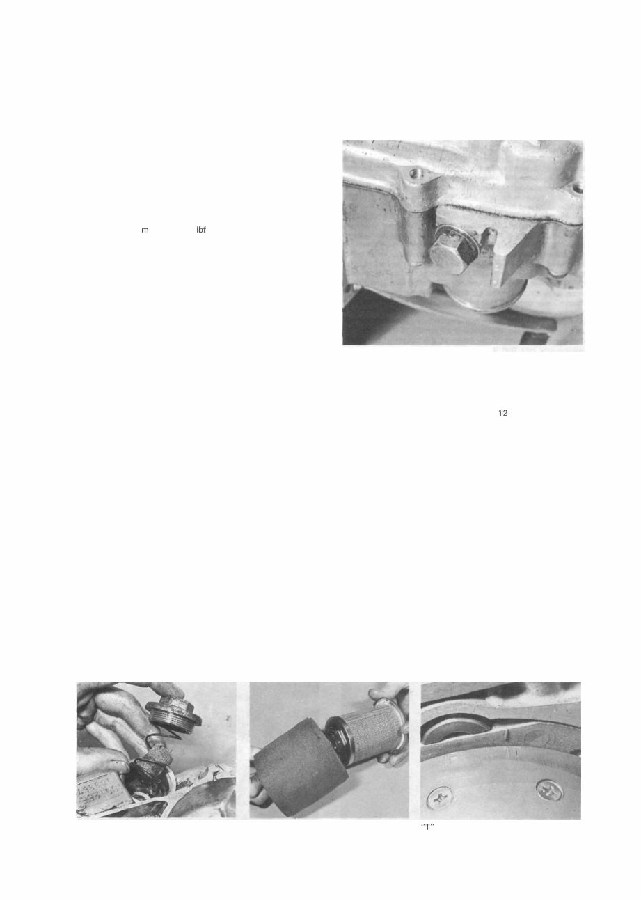
1 Change the engine oil and clean the filter gauze
This is the specified interval at which the engine/gearbox oil
should be changed; in normal use it should be regarded as the
maximum permissible.
It is recommended that the oil be changed after a run to
ensure that the engine is warm. This helps the oil to drain
thoroughly. Obtain a container of at least 1 litre (1.76 pints)
Free play can be felt via the inspection hole Move each adjuster by an equal amount
'
10 Routine maintenance
capacity and place it beneath the engine unit to catch the old
oil. Unscrew the drain plug on the underside of the crankcase
and allow the oil to drain.
Remove the large hexagon-headed plug which is located
just below the left-hand engine casing. Remove the plug,
followed by the spring and gauze element, and then wash all
these components carefully in a suitable solvent. Wipe out any
residual oil from the housing with a clean lint-free rag prior to
reassembly. Refit the drain plug, tightening it to a torque setting
of 2.0 - 3.5 kgf m (14.5 - 25 Ibf ft), and refill the engine with
the correct quantity and grade of oil.
Six-monthly, or every 3600 miles (6000 km)
Repeat all service operations listed under previous
headings, then carry out the following:
/ Clean the air filter
Pull off the right-hand side panel and remove the two nuts
which secure the air filter cover. Withdraw the cover, checking
that the sealing gasket is in good condition, pull out the
retaining spring and withdraw the element assembly. Peel off
the inner and outer foam sleeves. Wash all components in white
spirit (Stoddard solvent) or in warm water and detergent and
dry them thoroughly. Soak the foam sleeves in the specified oil,
then squeeze them gently (do not wring them out or they will be
damaged) to expel all surplus oil. Refit the sleeves to the
element frame. On reassembly ensure that all components are
correctly fitted so that unfiltered air cannot bypass the element.
2 Check the spark plug
Remove the spark plug cap, unscrew the plug and check its
condition, comparing it with the photographs on page
65. If it is badly worn or fouled it must be renewed. If it is fit for
further service check the gap and reset it if necessary, as
described in Chapter 3.8.
3 Check the valve clearances
It is important that the correct valve clearance is
maintained. A small amount of free play is designed into the
valve train to allow for expansion of the various components. If
the setting deviates greatly from that specified, a marked drop
in performance will be evident. In the case of the clearance
becoming too great, it will be found that valve operation will be
noisy, and performance will drop off as a result of the valves not
opening fully. If on the other hand, the clearance is too small
the valves may not close completely. This will not only cause
loss of compression, but will also cause the valves to burn out
very quickly. In extreme cases, a valve head may strike the
piston crown, causing extensive damage to the engine. The
clearances should be checked and adjusted with a cold engine.
Place the machine on its centre stand and remove the
rocker cover, taking care not to damage the 0 ring. Remove the
gearchange pedal and the left-hand outer cover to expose the
generator rotor.
Remove plug and allow old oil to drain
Remove the spark plug, then slowly rotate the engine anti-
clockwise by way of the generator rotor, watching the inlet
valve. When it has opened and closed again (sunk down and
risen up to its original position), rotate the engine further until
the T mark on the rotor periphery aligns exactly with the raised
index mark which is positioned between 12 and 1 o'clock (from
the crankshaft) on the generator stator. The engine will then be
in the correct position for checking the valve clearances, namely
at Top Dead Centre (TDC) on the compression stroke; check
that there is free play at both rockers.
Using a 0.08 mm (0.003 in) feeler gauge, check the
clearance between the top of each valve stem and its cor-
responding rocker. The feeler gauge must be a light sliding fit,
with the rocker and valve stem just nipping it. If necessary,
slacken the locknut, and turn the small square-headed adjuster
to obtain the correct setting. Tighten the locknut, holding the
adjuster at the same time to prevent it from moving. Finally,
recheck the setting and then repeat the procedure on the other
rocker.
4 Check the contact breaker points and ignition
timing
Note: since the generator stator plate is located by its
countersunk retaining screws, the ignition timing can only be
altered by opening or closing the contact breaker gap; therefore
both operations are described as one. The full procedure is
given here for ease of reference, but if the points are found to
be in good condition and if the gap has not altered or is within
the tolerance, then the ignition timing will be sufficiently
accurate and there will be no need to carry out the full check.
First remove the gearchange pedal, the left-hand outer cover,
the spark plug and the left-hand side panel.
Strainer is easily removed for cleaning Dismantle the element for cleaning -j- mark should align as shown
and lubrication
You're Reading a Preview
What's Included?
Fast Download Speeds
Online & Offline Access
Access PDF Contents & Bookmarks
Full Search Facility
Print one or all pages of your manual
$31.99
Viewed 25 Times Today


Secure transaction
What's Included?
Fast Download Speeds
Online & Offline Access
Access PDF Contents & Bookmarks
Full Search Facility
Print one or all pages of your manual
$31.99
- This comprehensive service manual is essential for owners of CG125 motorcycles manufactured between 1976 and 1991. It contains all the vital information required for bike maintenance and servicing.
- The manual provides detailed instructions for various CG125 models, covering the range from the initial 1976 version to the latest model released in September 1991. Each model is clearly identified with its corresponding year range, ensuring that owners have the correct information for their specific bike.
- Whether you own the CG125 from 1976 to 1978, the CG125K1 from 1978 to 1981, the CG125-B from 1981 to 1982, the CG125-C from 1982 to 1984, the CG125-E from 1984 to 1985, the CG125(BR)-E/F from 1985 to 1988, the CG125(BR)-J from 1988 to 1991, or the CG125(BR)-K from September 1991 onwards, this manual serves as the ultimate resource for all these models.
By following these instructions, you can effectively rephrase the product description while maintaining the existing information and improving clarity and coherence.


