

BS-BS
ATC ' 3!5DX
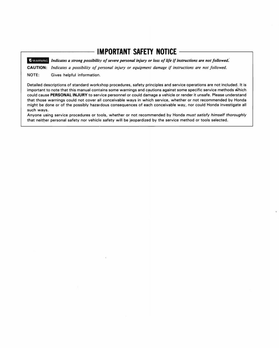
IMPORTANT SAFETY NOTICE ------,
' .... ' rrrdicarft II IITO"1 ponibillly of Uv~rt pHSOll aJ Injury Or /011 of 11ft If Instructions a" no / followtd,'
CAUTION: Ind/call'S II possibility 0/ personal i!tiury or equipment damage if ins/ruelions art 110/ JoI/o-..w1.
NOTE: Gives helpful information.
Detailed descriptions of standard workshop procedures. salety principles and service operations era not included. It is
imponanllO no te thaI this manual contains soma warnings lind eliutions against some specific service methods Which
could cause PERSONAL INJURY to se rvice personnel or could damage II vehicle or render it unsafe. Pl ea se understand
Ihal those warnings could not cover ell conceivable way s in wh ich service, whether Or not recommended by Honda
might be done Or of the possibly hazardous consequences of each conceivable way. nor could Honda investigate all
such ways.
Any one using service procedures or tools. whether or not recommended by Hornla must SlJlisfy himself thoroughly
that neill;oer personal safety nor vehicle safety will be jeopardized by the service method Or tools selected.
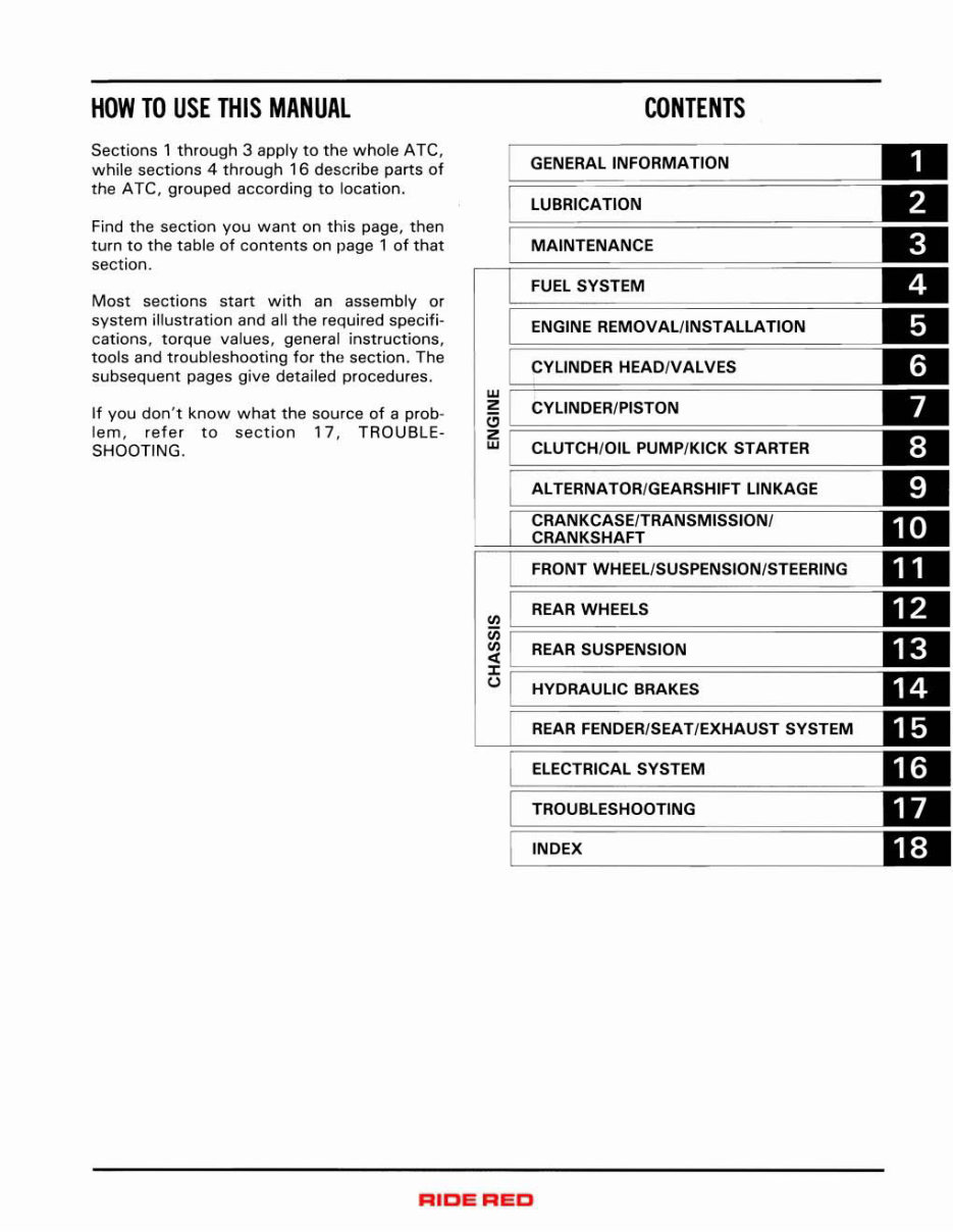
HOW TO USE THIS MANUAL
Sections 1 through 3 apply to th e whole ATC ,
while sections 4 through 16 describe parts of
the ATC, grouped acco rding to location.
Find the section you want on this page, then
turn to the table of contents on page 1 of that
section.
Most sections start with an assembly or
system illustration and all the required sp ecifi -
cations. torque values, general instructi ons,
tools and troubleshooting for the section. The
subsequent pages give detailed procedures.
If you don 't k now what the source of a prob-
lem , refer to section 1 7, TROUBLE-
SHOOTING .
CONTENTS
GENERAL INFORMATION
LUBRICATION
MAINTENANCE
FUEL SYSTEM
ENGINE REMOVAL/INSTALLATION
CYLINDER HEAD/VALVES
w ~=======================
Z CYLINDER /PISTON
8 F=====================
:;
CLUTCH/ Oil PUMP/KICK STARTER
ALTERNATOR/GEARSHIFT LINKAGE
FRONT WHEEl/SUSPENSION/STEERING
(Il I REAR WHEELS
~ I REAR SUSPENSION
iS l . HYDRAULIC BRAKES
F===== =============== ===
REAR FENDER/SEAT/ EXHAUST SYSTEM
ELECTRICAL SYSTEM
TROUBLESHOOTING
INDEX
RICE
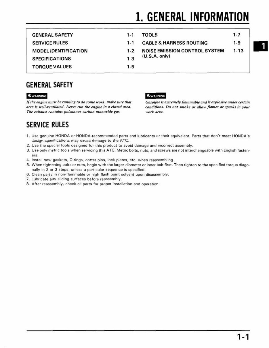
1. GENERAL INFORMATION
GENERAL SA FETY 1-1 TOOLS 1-7
SERVICE RULES 1-1 CABLE & HARNESS ROUTING l -S
MODEL IDENTIFI CA TION 1-2 NOISE EMISSION CONTROL SYSTEM 1-13
SPECIFI CA TIONS 1-3
(U.S .A . o nl y)
TORQUE VA LUES 1-5
GENERAL SAFETY
IWl,llii@
Ulf"iiiiild
If/hI tngint "III!! bl ,unning 10 do Jam" ... or k . mQ/ct SUre thar
area is w"I/·'-mli/flftrJ. N, ,-e, run fhl engine in a closed Qua.
Th t exhaust coma/ng poisonous carbon mo", ;Uidt gas.
Gasoli"t Is txl,emlly flammable {llld Is tx plosi.", undu Url a;n
conditions. Do not smakl o. 0110'" fl ames o r sptJrb in your
wurk {I reD.
SERVICE RULES
1, Use genuine HONDA or HONDA·recommended parts and lubricants or their equivalent. Parts lh,l1 dan', meet HONDA's
oo~i9n I'>p8ci hcations m,,'1 <:ause dilmage \0 the ATe.
2. Use the spedal tools designed for th is product to avoid damage and incorrect assembly.
3. Use only metric too ls when servidng th iS A TC. Metr ic bolts. nuts . and screws are not interchangeab le w ith English fasten-
ers .
4. Insta ll new gas kets. a -rings. cotter pins. lock plates, etc. when reassembling.
5. When t ightening bolts Or nut s, begin with the larger-diameter or inner bolt lirst. Then tighten to the specified torque diago -
nally in Z or 3 steps, unless a parti cular sequence is specified.
6. Clean parts in non-flammable Or high fl ash point solvent upon disassembly.
7. Lubr icate any sliding surfaces befo re reassembly.
a. Ahe r reassembly, chec k all parts f or proper installation and operat ion.
1-1
GENERAL INFORMATION
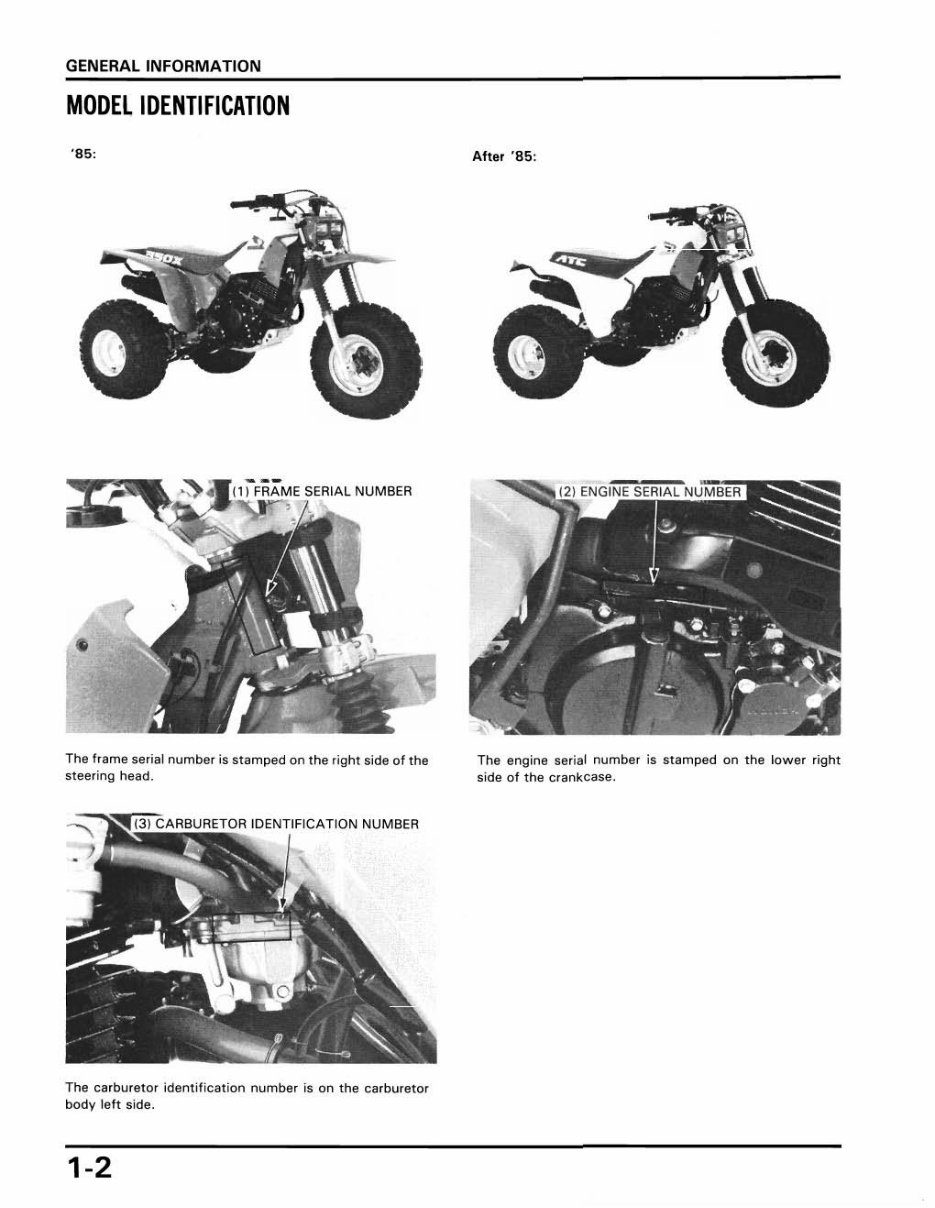
MODEL IDENTIFICATION
'8 5:
The frame serial number is stamped on the righ t side of the
steering head,
The carburetor ident ification number is on the carburetor
body l eft side,
1-2
After '85:
The engine serial number is stamped on the lower right
side of the crankcase.
GENERAL INFORMATION
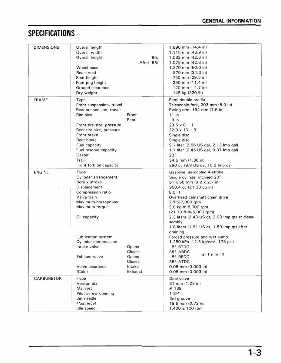
SPECIFICATIONS
DIMENSIONS Overall length 1,890 mm (7 4.4 inl
Overall width 1,115 mm (4 3.9 inl
Overall height '85 : 1,082 mm (42.6 inl
After '85 : 1.075 mm (42.3 inl
Wheel base 1,270 mm 150.0 inl
Rea r tread 870 mm 13 4.3 i nl
Seat hei ght 750 mm 129.5 inl
Foot peg height 290mm lll .4; n)
Ground clearance 120mm ( 4.7 in)
Dry we ight 145 kg 1320 Ibl
-
FRAME Type Semi-double c rad le
Front suspension. travel Telescopic fork. 203 mm (8.0 inf
Rear suspenSIon, travel Swing arm. 194 mm 17.6 inf
Rim size Front I 1 in
Rear 9 in
Front tire Size, pressu re 23.5xB - II
Rear ti re size, pressure 22 .0 xl 0- 9
Front brake Single disc
Rear brake Single disc
Fuel capacity 9.7 liter (2.56 US gal. 2.13 Imp gall
Fuel reSerVe capacity 1.7 liter (0.45 US gal. 0.37 Imp gall
Cas ter
,,"
Trail 34.5 mm 1 1.36 inl
Front fork oil capacity 290 cc (9.8 US oZ. 10.2 Imp ozl
ENGINE Type Gasoline. air-cooled 4-stroke
Cylinder arrangement Single cylinder inclined 20"
Bore x stroke 8 1 x 68 mm (3.2 x 2 .7 i nl
Displacement 350.4 cc (21.38 cu in)
Compressior> ratio 8.5: 1
Valve train Overhead camsh aft chain drive
Maximum hotsepower 27PSI7.000 ,pm
Max imum torque 3.0 kg-mI6.000 rpm
1 21.70 ft -lbI 6.000 rpm)
Oil capacity 2 .3 liters 12.43 US qt. 2.03 Imp qt) at disas-
sembly
I.Bliters II.9 1 US qt , 1.59 Imp qtl after
draining
Lubrication system Forced pressure and wet sump
Cylinder comp ression 1.250 kPa 112.5 kglem', 178 psi)
Intake valve Opens 5" BTDC
Closes 35" ABOC
,,'
mm li ft
Exhaust valve Opens 5° 8BDC
Closes 35° ATOC
Valve clearance I ntake 0.08 mm 10.003 inl
ICold) Exhaust 0.08 mm (0.003 inl
-
CARBURETOR T,~ Dual valve
Ventu, i dia. 31 mm 11. 22 inl
Main jet If- 138
Pilot sc'ew opening 1-314
Jet needle 3rd groove
Float level 18.5 rom 10.73 in/
Idle speed 1,400 % 100 ' pm
1-3
GENERAL INFORMATION
DRIVE TRAIN Clutch Wet mult i- plate
Transmi ssion 6-speed contl ant mesh
Pr imary !eduction 2,833 (68/24)
Gear rat io
,
2.750 (44/ 1S)
Gea •• atio
"
2.050 (4 1120)
Gear ratio
'"
I.S09137 /23)
Gea. ratio
'V
1.308134 /2S)
Gear ratio V 1.103132 /2 9)
Gear ratio V, 0.935 (29/ 311
Final redllction 3.077 (40/131
Gearshift pattern Left foot operated retmn system ,
l- N- 2- 3- 4- 5- 6
Or ive chllin ,in/1inkt 520/90 li nk.
ELECTRIC AL Ignition system CO,
Init illl ignition timing 10° BTOC
FlIl) advllnCIt 30 ° BTOC
Attefnlltor 200 W/ S .OOO rpm
Spark plllg NGK ORBES -L
NO X24ESR - U
Spark plllg gap 0.B - 0 .7 mm (0.02 4- 0.028 in)
Helldl ight 12 V- 36.S/ 3S W x 2
Ta illight 12 V- S W
1-4
GENERAL INFORMATION
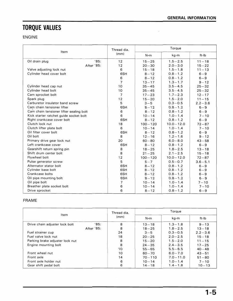
TORQUE VALUES
ENGINE
Th read di a.
Torque
It em
Imml
'·m
kg·m 1I · lb
Oil drain plug '85:
"
15 - 25 L5 2.5 11 -16
Alt er '65:
"
20 - 30 2.0-3.0 15 - 22
Valve ad justing loc k nut 6 15-16 1.5 - 1.6 11 -13
Cyl inder head cover boh 6SH 6- 12 0.8-1.2 6- 9
6 8-12 0.8 - 1.2 6- 9
2 13 - 17 1.3-1.7 9- 12
Cylinder head cap nut
W 35-45 3.5 -4 .5 25 - 32
Cylinder he ad bo lt W 35 - 45 3.5 -4 .5 25 - 32
Cam s proc ket bolt 2 17 - 23 1.7-2.3 12 - 17
Spark plug
"
15 -20 1.5 - 2.0 11 - 1 5
Carb uretor insulator band sCrew 5 3- 5
0.3 - 0.5 2.2 - 3.6
Ca'.." chain len"ioner lilter 6SH 8- 12 0.8-1.2
6-9
Cam chain tens i oner liller sealing bolt 6 8-12 0.8 - 1.2 6- 9
Kick staner ratchet guide soc ket bolt 6 10 - 14 1 .0 - 1.4 7-10
Right cra nkcase cover bolt 6SH 8-12 0.8 - 1.2
6-9
Clutch loc k nut
"
100 - 120 10.0-12.0 72 - 87
Clutch li lte r plate bolt
6 10 - 14 1.0 -1 .4 7- 10
Oil tilter cover boh 6SH 8-12 0.8 - 1.2
6-9
Oil bolt 8 12 -1 6 1.2 - 1.6 9- 12
Pr imary dr ive gear lock nut 20 60 - 80 6.0-8 .0 43 - 58
Left cra nk case cover 6SH 8- 12 0.8-1.2 6- 9
Gearshift return spri ng pi n
8 18 - 25 1.8 -2 .5 13 - 18
Shift drum ceme r boh
8 2 1 - 25 2. 1-2.5 15 - 18
Flywheel bolt
"
100-120 10.0 - 12 .0 72-87
Pul se generator SCrew
5 5- 2 0.5-0.7 3 .6 - 5.1
Alternator stator bolt 6SH 8-12 0.8 - 1.2 8-9
Cyl i nder base bolt 6SH 8-12 0.8 - 1.2
6-9
Crankcase bolts 65H 8-12 0.8-1.2
8- 9
O il pipe mounting bolt 69H 8- r2 0.8-1.2
6- '
Oil p i pe bolt 2 10 - 14 1.0 - 1.4 7- 10
Breather plale soc ket bolt
6 10 - 14 1.0-1.4 7- 10
Orive sprOcket 6 8-12 0.8 - 1.2 6-9
FRAME
Thread dia.
Torq ue
Item
Imml
'·m
kg·m ft·lb
Drive chain adjuster lock bolt ·85:
8
" "
,
.3 La 9
"
Af t er ·85: 8 18 - 25
,
.8 - 2.5 13-18
Fuel slraine r cu p
"
3- 5 0.3 - 0.5 2.2 - 3.6
Fuel va lve lock nut
"
20 - 25 2.0-2.5 15 - 18
Pa rking brake adjuster lock nut 8 15 - 20 1.5 - 2.0 11 -15
Engine mount ing bolt 8 24-35 2.4 - 3.5 17-25
'0
55 - 65 55-6 .5 40 - 48
Front wheel nut W 60-70 6.0 - 7.0 43-51
Front axle
"
70-110 7 .0 - 11.0 51-80
Front axle holder nut 6 10-14 1 .0 - 1.4 7- 10
Gear shift pedal bolt 6 14 -18 1.4 _ 1.8 10 _ 13
1-5
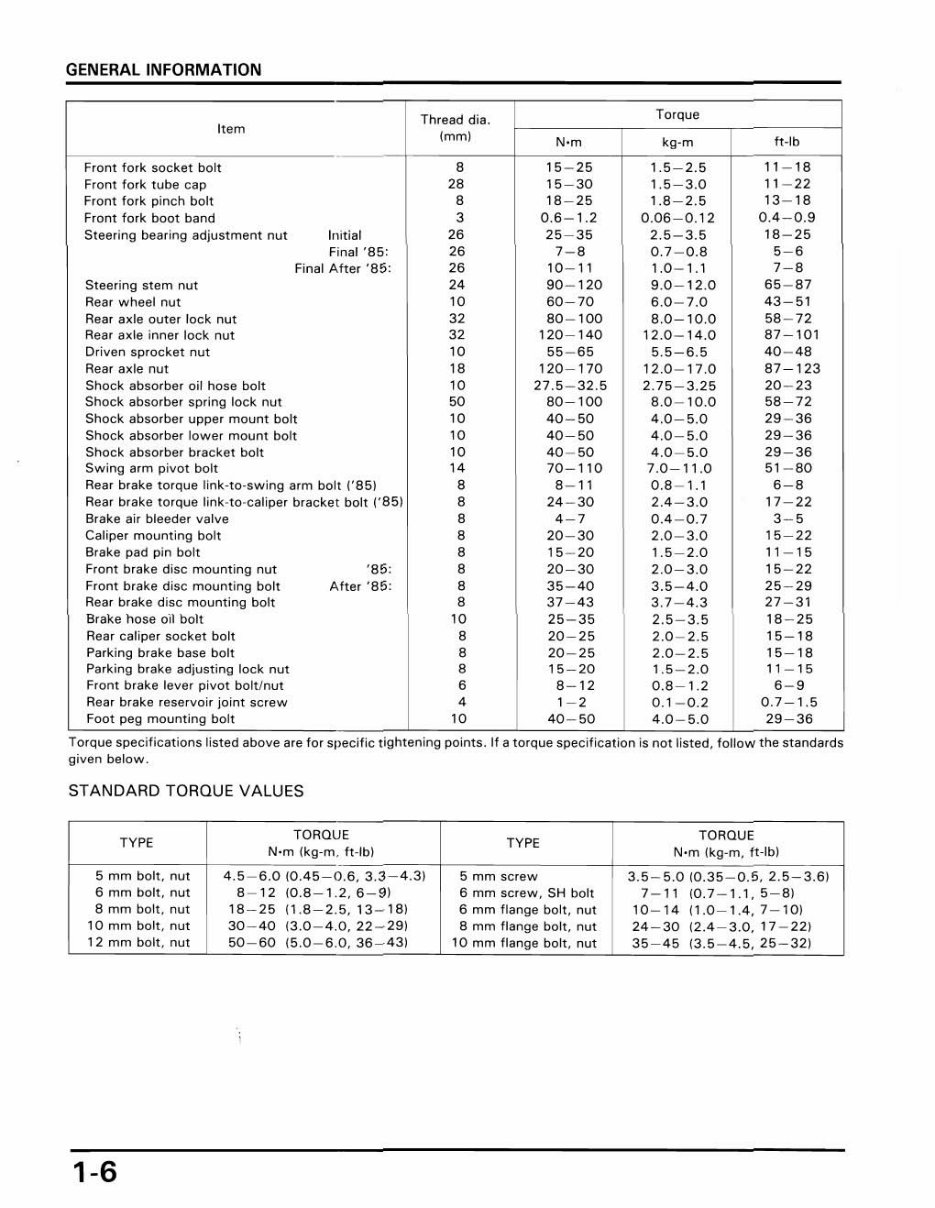
GEN ERAL INFORMATION
Thread dia.
Torq ue
Item
(mm)
N'm
kg-m It-Ib
From l ork socket bolt 8 15 25 1.5 2.5
"
18
Fronl fork lube cap 28 15-30 1. 5-3 .0 11 - 22
Front fork pinch bo ll 8 18-25 1.8-2.5 13 - 18
Front fork boot band 3 0.6- 1.2 0.06-0 . 12 0.4-0.9
Steer i ng bearing adjustment nut Ill itial 26 25 - 35 2.5 - 3.5 18 - 25
Final '85: 26 '-8
0 .7 - 0.8 5-8
Final After '85: 26 10 - 11 1.0 - 1. 1
'-8
Steer in g stem nut
"
90 -1 20 9.0-12 .0 65 - 87
Rear wheel nut
"
60-70 6.0 - 7.0 43 - 51
Rear axle outer lock nut 32 80 - 100 8.0 - 10.0 58 - 72
Reat axle inner lock nut 32 120 - 140 12 .0 - 14.0 87-101
Dri ve n sprocket nut
"
55 - 65 5.5- 6.5 40 - 48
Rear axle nut 18 120 - 170 12 .0 - 17.0 87 -1 23
Shoc k absorber oil hose bolt
"
27.5 - 32 .5 2.75-3 . 25 20 - 23
Shock absorber spr ing lock nut 50 80-100 8.0 - 10 .0 58-72
Shock absorber upper moun t bo ll
"
40 - 50 4.0-5.0 29 - 36
Shoc k absorber lower mount bo lt
"
40-50 4.0 - 5.0 29 - 36
Shock absorber bracket bolt
"
40 - 50 4.0 - 5.0 29-36
Swing arm pi vot bolt
"
70 -1 10 7.0-11.0 51 - 80
Rear brake torque link · to·swing arm bolt 1"851 8 8- 11 0.8 - 1.1 6- 8
Rear brake torque link·to·caliper bracket boll 1"851 8 24 - 30 2.4- 3.0 17 - 22
8ra ke air bleeder valve 8
,-,
0.4 - 0.7 3- 5
Caliper mounting bolt 8 20 - 30 2.0 - 3.0 15-22
Brake pad pin bo lt 8 15 - 20 1.5 - 2.0 11 - 15
Front brake di sc moum i ng nut '85 : 8 20-30 2.0-3 .0 15 - 22
From brake disc mo unt i ng bolt After '85: 8 35 - 40 3.5 - 4.0 25-29
Rear brake disc moun ting bolt 8 37-43 3.7 - 4.3 27 - 31
Brake hose oil bolt 10 25 - 35 2.5 - 3.5 18 - 25
Rear cali per socket bolt 8 20-25 2.0- 2.5 15 - 18
Parking brake base bolt 8 20 - 25 2.0- 2.5 15-18
Parking brake adjus ting lock nut 8 15-20 1.5 _ 2.0 11 - 15
Front brake lever pivot bo lU nut 6 8- 12 0.8 - 1.2 6- 9
Rear brake rese rvoir joint screw
,
1- 2 0.1- 0.2 0.7- 1.5
Foot peg mouming bolt 10 40- 50 4 .0 - 5 .0 29-36
Torque spec rfr cat lons hsted above are for spec./ ,c tIghtening pomts. If a torque SpeCI/ICaI I On IS no t li sted , fol l ow the standards
gi ven below.
STANDARD TORGUE VALUES
TYPE
TOROUE
TYPE
TORQUE
Nom (kg-m. ft -Ib ) N·m (kg·m. ft-Ib)
5 mm boh, 00>
"
6.0 (0. 45 0.6.3 .3 4.3) 5 mm screw 3.5 5.0 1 0.35 0.5. 2.5 3.61
6 mm bolt. nut 8 - 12 (0 .8-1 . 2.6-9 ) 6 mm screw. SH bolt 7- 11 1 0.7 - 1.1.5-81
8 mm bolt. nut 18-25 1 1.8-2 . 5.13 - 181 6 mm fl ange bolt. nut 10 - 14 (1.0 - 1.4.7 - 10 1
10 mm bolt, om 30 - 40 (3.0- 4.0.22 - 291 8 mm flange bolt, nut 24-30 12.4 - 3.0, 17 - 22 )
12 mm bolt. nul 50 - 60 15.0- 6.0,36 - 431 10 mm flange boll, nut 35 - 45 13 .5- 4.5 , 25 - 32)
1-6
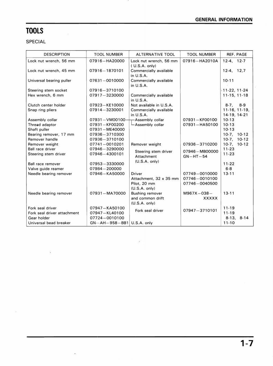
GENERAL INFORMATION
TOOLS
SPECIAL
DESCRIPTION TOOL NUMBER ALTERNATIVE TOOL TOOL NUMBER REF. PAGE
Lock nut wrench. 56 mm 07916 HA20000 Lad nut wrench. 56 mm 07916 HA2010A 12-4. 12·7
I U.S.A. onlyl
Lock nut wrench. 45 mm 07916 - 1870101 Commercially available 12-4. 12.7
in U.S.A.
Universal bearing puller 07631 - 0010000 Commercially available 10- 11
in U.S.A .
Steering stem socket 07916 - 3710100 . 11 - 22.11 · 24
He~ wrench. 6 mm 07917 - 3230000 Commercially available 11 - 15.11 · 18
in U.S.A,
Clutch center holder 07923 - KEloooo Not available in U.S.A. 8-7.
,.,
Snap ring pliers 07914-3230001 Commercially available 11_16,11_19.
in U.S.A. 14-19, 14- 21
Assembly collar 07931 - VMOOI 00 h-Assembly collar 07931 - KF00100 10- 13
Thread adaptor 07 9 31 - KF00200 I L...Assembly collar 07931 - HAS0100 10- 13
Shah puller 07931 - ME40000 10- 13
Bearing remove., 17 mm 07936 - 3710300 10- 7, 10 · 12
Remover handle 07936-3710100 10_7, 10·12
Remover weight 07741 - 0010201 Remover weight 07936 - 3710200 10·7. 10· 12
Ball race driver 07946-3290000
Steering stem driver 079 46- MBOOOOO
11-23
Steering stem driver 07946 - 4300101
Attachment GN-HT-54
11 · 23
Bal l race remOve. 07953 - 3330000
IU.S.A. only)
11 · 22
Valve guide reamer 07984-200000
,.,
Needle bearing remOver 07946 - KA5oooo Dr iver 07749 - 0010000 13· 11
Attachment. 32 x 35 mm 07746 - 0010100
Pilot. 20 mm 07746-0040500
IU.S.A. only)
Needle bearing remove, 07931 - MA7oooo Bushing remover M967X - 038 - 13- 11
and common drift XXXXX
(U.S.A. only)
Fork seal drive, 07947 - KA50100
Fork seal driver 07947-3710101
11 - 19
Fork seal driver al1achment 07947 - KL40100 11 -1 9
Gear holder 07724 - 0010100 8·13. 8· 14
Universal bead breaker GN--AH-958-BBI U.S.A. only 11·10
1-7
You're Reading a Preview
What's Included?
Fast Download Speeds
Online & Offline Access
Access PDF Contents & Bookmarks
Full Search Facility
Print one or all pages of your manual
$27.99
1985-1986 HONDA ATC 350x 3-Wheeler Service Repair Manual ATC350 - IMPROVED -
Viewed 18 Times Today

What's Included?
Fast Download Speeds
Online & Offline Access
Access PDF Contents & Bookmarks
Full Search Facility
Print one or all pages of your manual
$27.99

Secure transaction
What's Included?
Fast Download Speeds
Online & Offline Access
Access PDF Contents & Bookmarks
Full Search Facility
Print one or all pages of your manual
- This Complete Honda ATC350X two-stroke trike Official Factory Service Repair Technical Manual includes detailed diagrams and manufacturers specifications for maintaining and servicing your equipment.
- Improved manuals have bookmarks, searchable text, and improved quality.
- Models covered:
- 1985 Honda ATC 350X
- 1986 Honda ATC 350X
- Navigation is simple with convenient chapter bookmarks and the ability to search by keyword.
- Zoom it, print it, save it, and close it. Print a few pages at a time or the entire manual. No need to worry about dirty, torn, or missing pages.
- All diagnostic and repair procedures are covered.
- This Manual is a must for both professional mechanics and DIY enthusiasts!
- Instant access - no waiting
- Language: English
- Format: .PDF
- Compatible with all versions of Windows, Mac, iOS, BB, Android, etc
- Pages: 231
- Searchable, bookmarked, indexed
- Detailed illustrations, exploded diagrams, drawings, and photos guide you through the service repair procedures.
Contents:
- General Information
- Lubrication
- Maintenance
- Fuel System
- Engine Removal / Installation
- Cylinder Head / Valves
- Cylinder / Piston
- Clutch / Oil Pump / Kick Starter
- Alternator / Gearshift Linkage
- Crankcase / Transmission / Crank Shaft
- Front Wheel / Suspension / Steering
- Rear Wheels
- Rear Suspension
- Hydraulic Brakes
- Rear Fender / Seat / Exhaust System
- Electrical System
- Troubleshooting
- Index
Lots of pictures, diagrams, illustrations, and charts. Technical details and step-by-step instructions you will need are included.
Additional Information: Documents may require the newest version of Acrobat Reader to display correctly. Should you have any problems reading your document, please initially try upgrading to the latest version of Adobe Acrobat Reader. I have Thousands of Manuals - email me about any you might need.


