

BSA M20 500CC Workshop Repair Manual All Models Covered
What's Included?
Fast Download Speeds
Online & Offline Access
Access PDF Contents & Bookmarks
Full Search Facility
Print one or all pages of your manual

Book No. 100/BC2C
Air Publication No. 1657B, Vol.1. Parat2
Maintenance Manual
And
Instruction Book
For
MOTOR CYCLE (SOLO)
500 c.c. s.v.
Model M20
Downloaded from www.Manualslib.com manuals search engine

INDEX – GENERAL
Pages Pages
Brakes 28 Front Forks 23
Carburetter 10 Gearbox and Gearchange 25
Clutch 21 Hubs 27
Charging System 36 Ignition System 32
Electrical Wiring System 30-31 Lighting and Accessories 42
Engine Adjustments 8 Lubrication System 3
Engine – Complete dismantling 12 Lubrication Chart 4-5
Engine – Decarbonising 11 Steering Head 28
Engine – re-assembly 16 Transmission 20
Engine – removal from frame 12 Useful Data 2
INDEX – DETAILS
Pages Pages
BRAKES Ignition System - continued
Adjustment – Relining 28 Slipping clutch – sparking plug -
CARBURETTER Suppressor - immobiliser 33
Mixture – Needle position – Pilot adjustment – Re-assembling and testing slipping clutch 35
Throttle stop. 10 Lighting and Accessories
ENGINE ADJUSTMENTS Headlamp – Tail lamp – Cables - Lighting
Oil-pressure valves – Exhaust valve lifter 8 switch 42
Tappets – Ignition timing 8-9 Horn 43
ENGINE DISMANTLING Wiring diagrams 30-31
Cylinder head – Cylinder barrel – Valves 6-7
Valve grinding – Valve guides, removal FRONT FORKS
and replacement 11 Adjustment 28
Piston and Rings – Checking ring gap – Dismantling – fitting new spring – re-assembly 29
removing engine from frame 12
Removing Magdyno pinion 13 GEARBOX
Oil pump, removal and dismantling – Removal – dismantling 23
“Splitting” crankcase – removing Dismantling Gearchange – Re-assembling
Bearings 14 Gearbox 24
Removing cam spindles – dismantling Re-assembling gearchange 25
flywheels – reboring cylinder - fitting Replacing gearbox 26
new cylinder lining. 15
ENGINE RE-ASSEMBLY HUBS
Flywheel assembly and alignment 16 Rear – adjustment – dismantling and
Replacing oil pump – tappets – replacing Re-assembly 27
bearings – re-assembling crankcase - Front 27-28
Replacing timing gears & magdyno 17
Replacing piston – cylinder barrel - timing LUBRICATION
Cover – cylinder head – exhaust valve Engine lubricating system 3
lifter – refitting engine in frame. 18 Lubrication chart 4
ELECTRICAL EQUIPMENT Hubs – Brake cam spindles - Speedometer
Charging System Drive – Filters – Rear chain – Dynamo -
Dynamo Gearbox 5
Testing – Removal and Replacement 36 Oil pump – removal – dismantling and
Dismantling – Brushes - Commutator 37 Re-assembly 14
Field coil, testing and removing -
Armature – Bearings 38 TRANSMISSION
Re-assembly 39 Clutch – adjustment 20
Cut-out and Regulator 39 Clutch – dismantling 21
Cleaning contacts – setting regulator - Clutch – re-assembly 22
Cut-out 40 Chaincase - removal 12
Ammeter – Removal and Replacement 41 Chaincase - replacement 18
Battery – Care of 41 Chain adjustment 20
Ignition System Wheel alignment 21
Magneto lubrication – adjustment – testing -
Cleaning contact breaker – H.T. cable - SHOCK ABSORBER – Adjustment 28
Pick-up 32
Removal – dismantling – removing and STEERING HEAD
testing armature 34 Adjustment 28
Re-assembly 35 Dismantling – re-assembly 29
Downloaded from www.Manualslib.com manuals search engine

1
Downloaded from www.Manualslib.com manuals search engine

USEFUL DATA
Engine bore 82 mm
Engine stroke M20 94 mm
Engine stroke M21 112 mm
Engine Capacity 496cc
Petrol tank capacity 3 gallons
Oil tank capacity 5 pints
Gearbox capacity 1 pint
Inlet tappet clearance (cold) .010”
Exhaust tappet (cold) .012”
Compression M20 4,9:1
Compression M21 5:1
Tyres 3.25/3.50-19
Tyre Pressure 22psi
Piston ring gap .008 - .012”
Piston clearance Bottom of skirt .0035 - .0055”
Piston Ring side clearance .002" - .004"
Ignition timing 7/16” BTDC
Magneto point gap .012”
Spark plug gap .012 - .018”
Carburetter- Jet 170
Carburetter- Needle 2nd notch
Engine Sprocket 19 teeth
Clutch sprocket 43 teeth
Gearbox Sprocket 18 teeth
Rear Wheel Sprocket 42 teeth
Primary Chain 95 links
Gear Ratio- Top 5.3
Gear Ratio- 3rd 7.0
Gear Ratio- 2nd 10.9
Gear Ratio- 1st 15.8
Downloaded from www.Manualslib.com manuals search engine

2
Downloaded from www.Manualslib.com manuals search engine
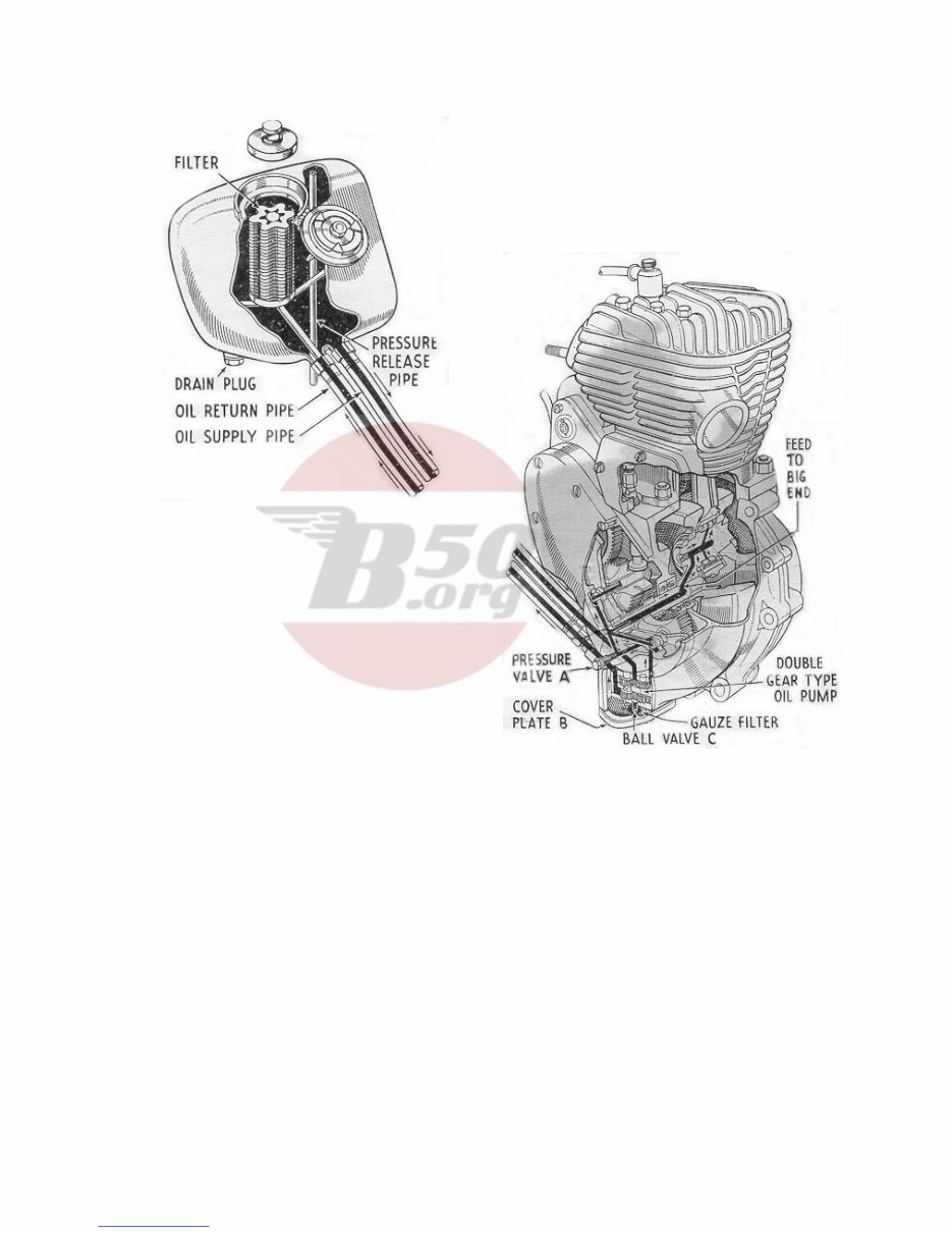
THE LUBRICATION SYSTEM
Fig. 1. Lubrication System
The engine lubrication system is of the dry sump type
operated by a double gear pump, situated in the
bottom of the crankcase on the right-hand side.
All oilways are internal except for the supply and
return pipes from the tank. The oil flows from the
tank to the supply pump (the top pair of gears) and
thence past the pressure valve (A) to the two oilways
feeding the cam spindles, and along the hollow
mainshaft to the big end bearing. After lubricating
the big end and circulating through the engine in the
form of a mist, the oil drains down through a filter in
the bottom of the crankcase, from which it is drawn
by the return pump (lower pair of gears) past ball
valve (C), and delivered up the return pipe to the
tank, where it passes through a fine mesh filter into
the tank itself.
Incorrect seating of the ball valve (A), will allow oil to
transfer from the tank to the engine, whilst the
machine is stationary. If the ball valve (C) should get
stuck in its seating, there will be no return of oil to the
tank. To check the oil circulation open the tank filler
cap and remove filter cap whilst the engine is
running. Oil should be seen issuing from the return
pipe from the crankcase. The tank and crankcase
should be drained every 2,000 miles and replenished
with clean oil.
Any restriction in the pressure release pipe in the
tank will cause an increase in pressure inside the oil
tank, and will result in leakage of oil at the filler cap.
This can be put right by inserting a length of flexible
wire into the pipe at its lower end (just in front of the
rear mudguard) and pushing the wire right up the
pipe, thus clearing any obstruction.
To remove the oil tank filter for cleaning, release the
tank filler cap, release the filter tap thus exposed, and
lift filter out. The filter should be placed in a can large
enough to cover it with petrol, and thoroughly
washed. Before replacing make sure that it is quite
dry of petrol.
The pump filter can be withdrawn after removing the
cover plate (B) and should be thoroughly washed
with petrol, dried and replaced.
NOTE. It is not advisable to remove the oil pump
unless the pump is definitely faulty.
3
Downloaded from www.Manualslib.com manuals search engine
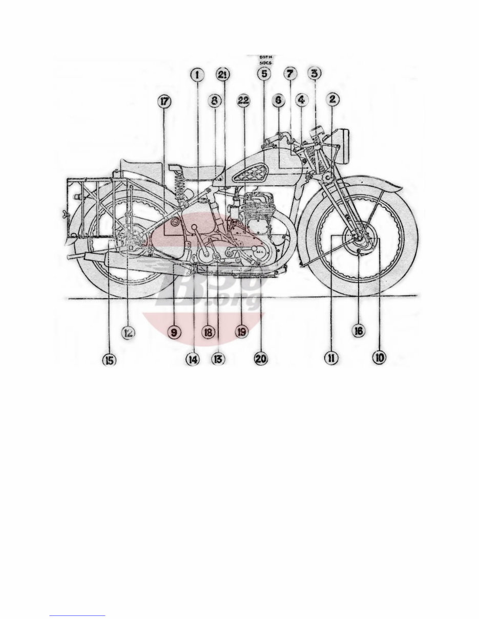
LUBRICATION
Fig 2. – Lubrication Chart
Downloaded from www.Manualslib.com manuals search engine

4 LUBRICATION CHART
No PART Lubricant Type of
Lubrication
Daily 250 Miles
(Inclusive)
General
FRAME GROUP
3 Front fork (top) CG-1 (AL) 1 nipple Grease Gun
2 Front fork (centre) CG-1 (AL) 1 nipple Grease Gun
4 Steering Stem (top) CG-1 (AL) 1 nipple Grease Gun
5 Steering Stem (bottom) CG-1 (AL) 2 nipple Grease Gun
7 Steering Head (top) CG-1 (AL) 1 nipple Grease Gun
6 Steering Head (bottom) CG-1 (AL) 1 nipple Grease Gun
8 Saddle nose pivot CG-1 (AL) 1 nipple Grease Gun
11 Front wheel hub CG-1 (AL) Re pack - Re pack w shops every 5000 miles
12 Rear wheel hub CG-1 (AL) Re pack - Re pack w shops every 5000 miles
BRAKE GROUP
9 Brake pedal CG-1 (AL) 1 nipple Grease Gun
16 Brake cam (front) CG-1 (AL) 1 nipple Grease Gun
15 Brake cam (rear) CG-1 (AL) 1 nipple Grease Gun
Bowden control wire OE-30 Oil Can Few Drops
Foot brake linkage OE-30 Oil Can Few Drops
ENGINE GROUP
1 Engine oil tank OE50 5 pints Replenish Replenish Drain & refill at 1000 miles (AO17)
19 Primary chain case OE50 Reservoir Replenish Replenish Drain & refill at 1000 miles (AO17)
1/20 Oil Filters OE50 Wash in petrol every 2000 miles
IGNITION GROUP
Advance Retard Cable etc OE30 Oil Can Few drops
Contact breaker tappet OE30 Oil Can One drop
22 Contact breaker cam CG-1 (AL) Hand smear Slight smear
Generator (drive end) WB-2 Re pack Re pack w shops
21 Generator (commutator end) OE30 Oil Can Few drops
FUEL GROUP
Air cleaner N/A
Carburetter control cables OE30 Oil Can Few drops
Throttle handle bar grip OE30 Oil Can Few drops
TRANSMISSION GROUP
10 Speedometer drive CG-1 (AL) 1 nipple Grease Gun
Speedometer cable OE30 Oil can Few drops
14 Gear box GO-90 1 pint Replenish Drain & refill each 6000 miles No 18
12 Clutch push rod OE-50 Oil can Few drops
Clutch bowden control wire OE30 Oil can Few drops
Clutch handle bar grip OE30 Oil can Few drops
Rear chain OE30 Oil can Few drops Wash in paraffin and soak in oil OE-
50 every 2000 miles. Workshops
5
Downloaded from www.Manualslib.com manuals search engine
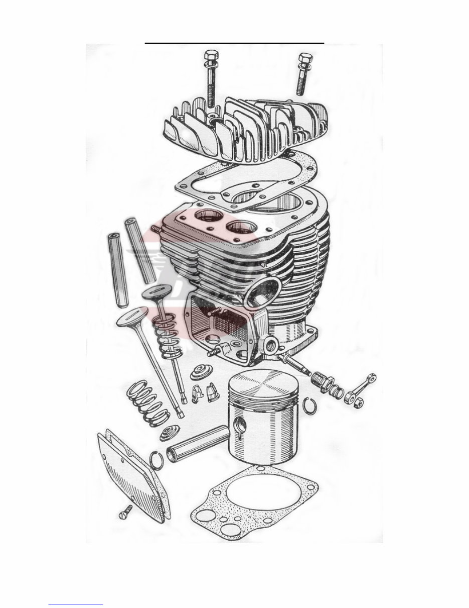
THE ENGINE – EXPLODED VIEW
Fig. 3. Top half of engine (exploded view)
6
Downloaded from www.Manualslib.com manuals search engine
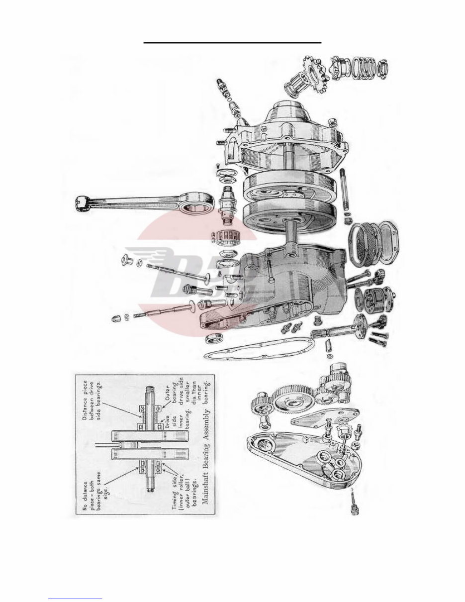
THE ENGINE – EXPLODED VIEW
Fig.4. Crankcase half of engine (exploded view)
7
Downloaded from www.Manualslib.com manuals search engine
You're Reading a Preview
What's Included?
Fast Download Speeds
Online & Offline Access
Access PDF Contents & Bookmarks
Full Search Facility
Print one or all pages of your manual
$30.99
Viewed 50 Times Today


Secure transaction
What's Included?
Fast Download Speeds
Online & Offline Access
Access PDF Contents & Bookmarks
Full Search Facility
Print one or all pages of your manual
$30.99
This Workshop Service Repair Manual is an essential resource for both professional mechanics and DIY enthusiasts. It contains all the technical information required to perform a wide range of repairs on BSA M20 500CC models. The manual includes detailed repair procedures, easy-to-read exploded views, diagrams, illustrations, specifications, step-by-step instructions, and much more, making service and repairs simple and accurate. Whether it's servicing, teardowns, overhauls, adjustments, or complete specifications, this top-quality Workshop Manual provides comprehensive repair information. It is available in instant PDF format, compatible with all computers, including PC and Mac.


