2013-2016 BMW R 1200 GS Electrical Wiring Diagrams Manual
What's Included?
Lifetime Access
Fast Download Speeds
Online & Offline Access
Access PDF Contents & Bookmarks
Full Search Facility
Print one or all pages of your manual
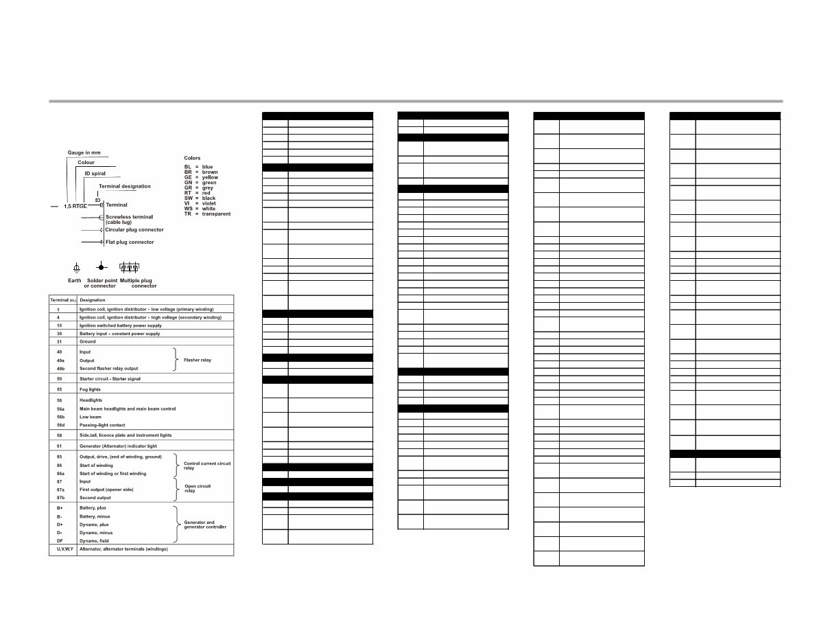
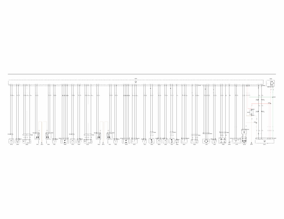
Wiring - 1/2 R 1200 GS Te rm in a l D e s ig n a tio n s & E le c tric a l C o m p o n e n t L egends R 120 0 G S Intro d u c tio n A A9001 In s tru m en t c lu s ter A9006 O n -b o ard co m pu ter (B C) A9190 AB S c o n tro l u n it A92 7 0 Z FE c o n tro l m o d u le A95 00 B M S K C o n tro l M o d u le A97 00 T heft a la rm (D W A) c o n tro l B B 9193 F ro n t AB S s en s o r B 9194 Rea r AB S s en s o r B 92 10 V ehic le s peed s en s o r B 92 2 0 F u el lev el s en s o r B 93 2 5 K nock S en s o r C y l 1 B 93 2 6 E n g in e s peed & Referen c e S en s o r B 95 3 1 C am s ha ft P o s itio n S en s o r B 95 5 0 T em pera tu re s en s o r, a ir in ta k e B 95 6 2 T em pera tu re s en s o r, en g in e o il B 95 8 4 K nock S en s o r C y l 2 B 96 90 O xygen sensor 1 B 97 3 8 O xygen sensor 2 B 97 3 9 C y lin d er H ea d T em p S en s o r C y l 1 B 97 4 0 C y lin d er H ea d T em p S en s o r C y l 2 E E 9010 H ea d lig ht E 9011 Low b ea m hea d lig ht E 9012 H ig h b eam head lig ht E 9013 T a il lig ht E 9015 S id e lig ht G G 92 3 0 B a ttery G 92 4 0 Altern a to r H H 903 0 F ro n t left tu rn s ig n a l in d ic a to r H 903 5 Rea r left tu rn s ig n a l in d ic a to r H 904 0 F ro n t rig ht tu rn s ig n a l in d ic a to r H 904 5 Rea r rig ht tu rn s ig n a l in d ic a to r H 905 0 B ra k e lig ht H 915 0 H o rn H 93 4 0 Rea r lig ht K K 913 0 S ta rter re la y L L 95 5 3 E W S Rin g An ten n a M M 9100 F u el pu m p M 913 0 S ta rter M 95 5 2 Id le S p ee d S te p p e r M o to r C y l 1 M 95 7 9 Id le S p ee d S te p p e r M o to r C y l 2 P P 9002 Rev o lu tio n c o u n ter P 92 10 S peed o m eter R R95 7 0 T hro ttle po ten tio m eter (D KP) R993 1 L eft hea ted ha n d leb a r g rip R993 2 Rig ht hea ted ha n d leb a r g rip R994 3 G ea rb o x P o s itio n S en s o r S S 902 1 H azard w arning sw itc h S 905 1 B ra k e lig ht s w itc h, ha n d S 905 2 B ra k e lig ht s w itc h, fo o t S 906 0 Ig n itio n lig ht s w itc h S 906 3 B ra k e flu id lev el s e n s o r S 906 4 B ra k e flu id lev el s e n s o r S 907 0 L eft m u lti-fu n c tio n s w itc h S 907 1 H ig h b eam s w itc h S 907 2 H orn sw itc h S 907 3 L eft tu rn s ig n a l s w itc h S 907 4 H ea d lig ht fla s her S 907 5 B C s w itc h S 908 0 Rig ht m u lti-fu n c tio n s w itc h S 908 2 Rig ht tu rn s ig n a l s w itc h S 908 3 E m ergency stop sw itc h S 908 4 S ta rter s w itc h S 908 5 T u rn in d ic a to r c a n c el s w itc h S 9091 C lu tc h s w itc h S 9093 S id e- s t a n d s w itc h S 9095 O il pres s u re s w itc h S 9195 AB S b u tto n S 993 0 S w itc h fo r hea ted ha n d leb a r g rips T T 95 06 M a in Ig n itio n C o il C y l 1 T 95 07 M a in Ig n itio n C o il C y l 2 T 95 17 Au x ilia ry Ig n itio n C o il C y l 1 T 95 18 Au x ilia ry Ig n itio n C o il C y l 2 X X 9001 S T V B in s tru m en t c lu s ter X 9010 S TV B hea d lig ht X 9013 S TV B rea r lig h t - X 9014 S TV B ta il lig ht X 9018 S TV B s id e lig ht X 903 1 S T V B fro n t left tu rn s ig n a l - X 903 2 S T V B fro n t left tu rn s ig n a l + X 903 6 S TV B rea r left t u rn s ig n a l - X 903 7 S TV B rea r left t u rn s ig n a l + X 904 1 S T V B fro n t rig ht tu rn s ig n a l in d ic a to r - X 904 2 S T V B fro n t rig ht tu rn s ig n a l in d ic a to r + X 904 6 S TV B rea r rig h t tu rn s ig n a l in d ic a to r - X C o n tin u ed X 904 7 S TV B rea r rig h t tu rn s ig n a l in d ic a to r + X 905 1 S TV B b ra k e lig ht s w itc h, ha n d X 905 2 S TV B b ra k e lig ht s w itc h, fo o t X 905 4 S TV B b ra k e lig ht + X 906 0 S TV B Ig n itio n lig ht s w itc h X 906 3 S TV B b ra k e flu id level s en s o r X 906 4 S TV B b ra k e flu id level s en s o r X 907 0 S TV B le ft m u lti-fu n c tio n s w itc h X 908 0 S T V B rig ht m u lti-fu n c tio n s w itc h X 9091 S TV B c lu tc h s w itc h X 9093 S TV B p ro p s ta n d s w itc h X 9095 S T V B o il pres s u re s w itc h X 9100 S T V B fu el pu m p X 913 0 S TV B s ta rter rela y X 913 5 S T V B s ta rter ter. 5 0 X 913 6 S T V B s ta rter ter. 3 0 X 915 7 S T V B ho rn X 9190 S T V B AB S c o n tro l u n it X 9193 S T VB fro n t AB S s en s o r X 9194 S TV B rea r AB S s en s o r X 92 10 S T V B v ehic le s peed s en s o r X 92 2 0 S TV B fu el lev el in d ic a to r X 92 3 0 B a ttery po s itiv e X 92 3 1 B a ttery g ro u n d X 92 3 8 G ro u n d X 92 4 1 S TV B a ltern a to r + X 92 4 2 S TV B a ltern a to r X 92 7 0 S T VB Z F E C o n tro l M odule X 93 2 1 S T V B s o c k et X 93 2 5 K nock S en s o r C y l 1 X 93 2 6 S T V B C ra n k s ha ft en c o d er X 93 4 0 S TV B lig htin g / rea r d irec tio n in d ic a to r X 93 4 9 S T VB o ptio n a l a c c es s o ry X 94 01 C o n n ec to r 3 1 I X 94 12 C o n n ec to r 3 1 X 94 3 0 C o n n ec to r 3 0U X 94 5 0 C o n n ec to r 15 U X 94 6 8 C o n n ec to r 15 X 94 7 2 C o n n ec to r L o w b ea m hea d lig ht X 95 00 S T V B c o n tro l u n it, en g in e elec tro n ic s X 95 06 S TV B M a in Ig n itio n C o il C o n n ec to r C y l 1 X 95 07 S TV B M a in Ig n itio n C o il C o n n ec to r C y l 2 X 95 12 Ig n itio n c o il g ro u n d , c y lin d er N o . 1 X 95 14 Ig n itio n c o il g ro u n d , c y lin d er N o . 2 X 95 17 S TV B A u x ilia ry Ig n itio n C o il C onn C y l 1 X C o n tin u ed X 95 18 S TV B A u x ilia ry Ig n itio n C o il C onn C y l 2 X 95 3 1 C am s ha ft P o s itio n S en s o r C o n n ec to r X 95 5 0 S T V B tem pera tu re s en s o r, in d u c ted a ir X 95 5 2 Id le S p ee d S te p p e r M o to r C y l 1 X 95 5 3 S T V B E W S An ten n a Rin g X 95 6 2 S T V B tem pera tu re s en s o r, en g in e o il X 95 7 0 S T V B thro ttle po ten tio m eter X 95 7 2 P u rg e V a lv e C o n n ec to r X 95 7 9 Id le S p ee d S te p p e r M o to r C onn C y l 2 X 95 8 4 K nock S en s o r C o n n ec to r C y l 2 X 95 90 D ia g n o s is plu g X 96 01 S TV B in jec t io n v a lv e 1 X 96 02 S TV B in jec t io n v a lv e 2 X 96 2 7 C o n n ec to r W L X 96 3 0 S T V B c o n tro l u n it, en g in e elec tro n ic s II X 96 90 S T VB oxygen sensor X 97 00 S T V B D W A I X 97 3 8 O xygen S en s o r C o n n ec to r C y l 2 X 97 3 9 C y lin d er H ea d T em p S en s o r C y l 1 X 97 4 0 C y lin d er H ea d T em p S en s o r C y l 2 X 97 6 1 C o n n ec to r M -C AN -L O W I X 97 6 2 C o n n ec to r M -C AN -H IG H I X 97 6 3 C o n n ec to r M -C AN -L O W II X 97 6 4 C o n n ec to r M -C AN -H IG H II X 97 6 5 C o n n ec to r M -C AN -L O W III X 97 6 6 C o n n ec to r M -C AN -H IG H III X 993 1 S T V B L eft hea ted ha n d leb a r g rip X 993 2 S T V B Rig ht hea ted ha n d leb a r g rip X 994 3 C o n n ec to r G earbox P o sitio n S en s o r Y Y 95 7 2 E v a po ra tiv e S y s tem P u rg e V a lv e Y 96 01 In jec tio n v a lv e 1 Y 96 02 In jec tio n v a lv e 2
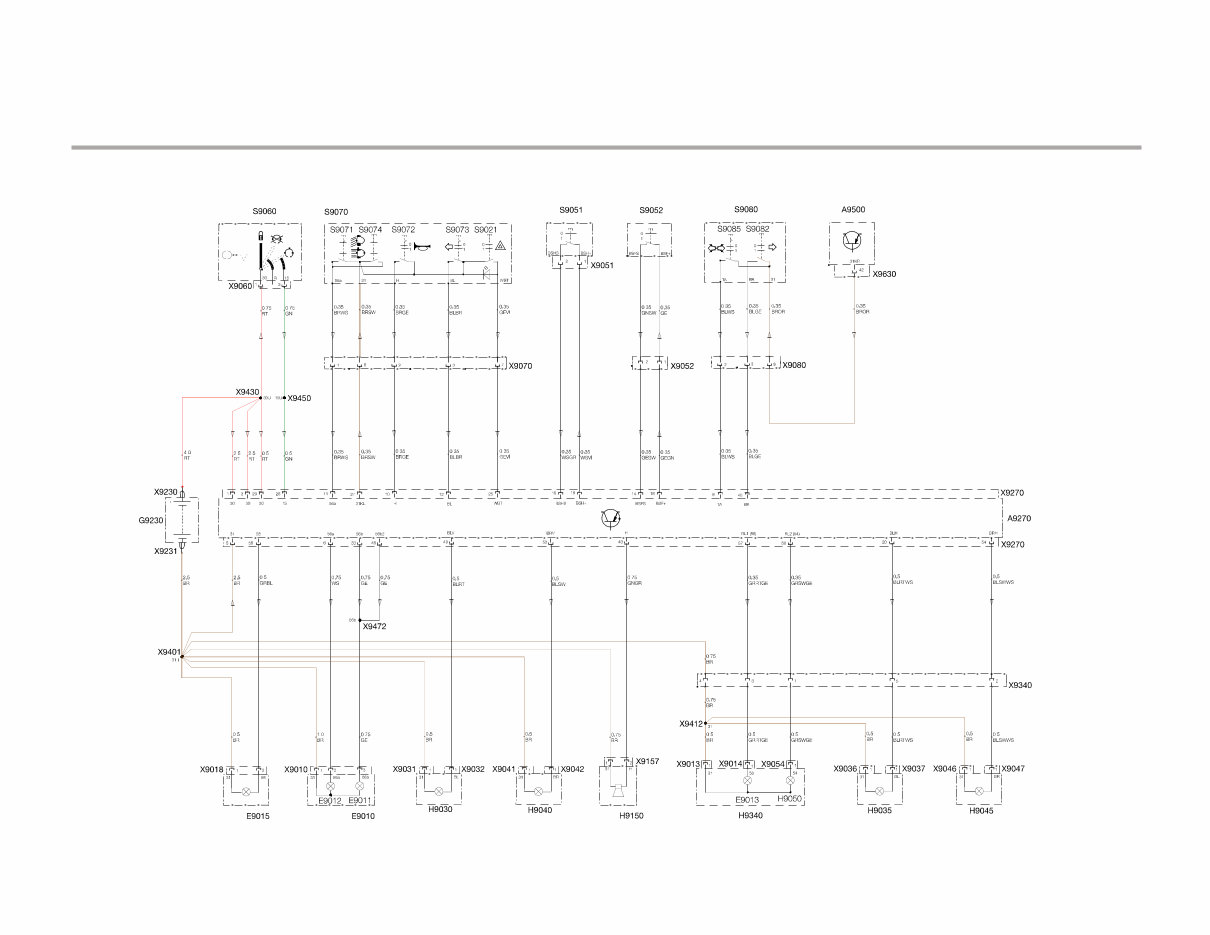
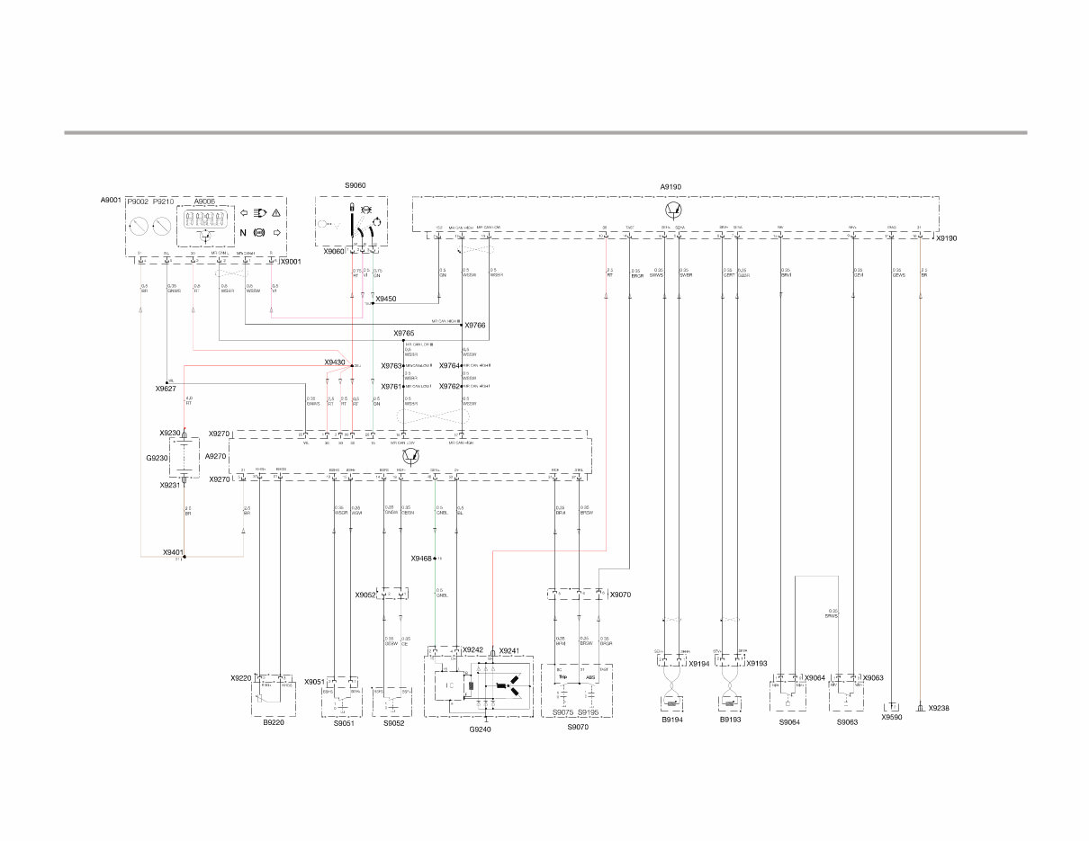
Wiring - 3/4 R 1200 GS Ligh ting/ Tu rn Signals/ H orn ( Z F E) ( Sch ematic I ) Ignition S w itch L e ft M u ltifu nc tion S w itc h F r ont B rake S w itch R e a r B rake S w itch R igh t M u ltifu nc tion S w itch ZFE C ontrol M od u le B a tte ry S id e L igh t H e a d ligh t F r ont L e ft B link e r F r ont R igh t B link e r H orn T a il L igh t R e a r L e ft B link e r R e a r R igh t B link e r B M S K R 1200 GS Introduction
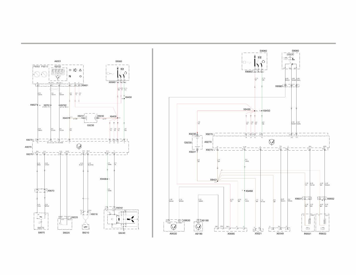
Wiring - 5/6 R 1200 GS P ow er Distrib ution and Grounds (Schematic II) BMS K Control Module I A BS Control Module A lternator Starter Starter Relay Ignition Switch Battery ZFE Control Module R 1200 GS Introduction
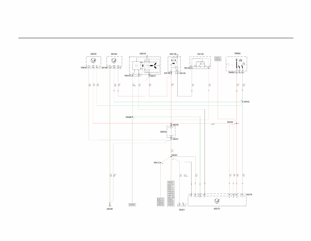
Wiring - 7/8 R 1200 GS Starter/A lternator (Schematic III) BMS K Ignition Switch ZFE Control Module Alternator Starter Starter Relay Starter Switch Clutch Switch Side Stand Switch G ear P os ition Sens or R 1200 GS Introduction
R 1200 GS B M S K - E n g in e M a n a g e m e n t (Sc h e m a tic IV ) Wiring - 9/10 Cylinder Head Tem p S ens o r (Cyl 1 ) K no c k S ens o r (Cyl 1 ) K no c k S ens o r (Cyl 2 ) O x yg en S ens o r (Cyl 1 ) O x yg en S ens o r (Cyl 2 ) M ain Ig nitio n Co il (Cyl 1 ) M ain Ig nitio n Co il (Cyl 2 ) A u x iliary Ig nitio n Co il (Cyl 1 ) A u x iliary Ig nitio n Co il (Cyl 2 ) F u el Injec to r ( Cyl 1 ) F u el Injec to r ( Cyl 2 ) Idle S p eed S tep p er M o to r (Cyl 1 ) Idle S p eed S tep p er M o to r (Cyl 2 ) Th ro ttle P o tentio m eter P u rg e V alv e P u rg e V alv e Intak e A ir Tem p S ens o r O il Tem p S ens o r O il P res . S w itch Cam s h aft P o s itio n S ens o r E ng ine S p eed & R eferenc e S ens o r G earb o x p o s itio n S ens o r S ide S t and S w itc h E W S A ntenna R ing Clu tc h S w itch R ig h t M u ltifu nc tio n S w itch D iag no s tic Co nnec to r S tarter R elay F u el P ump M o to r A9100 F u el Pump D riv er M o du le Z F E Co ntro l M o du le B attery Ig nit io n S w itc h B M S K Co ntro l M o du le Cylinder Head Tem p S ens o r (Cyl 2 ) R 12 00 G S Intro d u c tio n
Wiring - 11/12 R 1200 GS Integral AB S / I- Cluster (Schematic V ) Integral ABS Control Modulator Ignition Switch Battery ZFE Control Module I- Cluster Fuel Lev el Sensor Front Brake Switch Rear Brake Switch Alternator Left Multifunction Switch Rear W heel Sp eed Sensor Brake Fluid Lev el Switches D iagnostic Connector Front W heel Sp eed Sensor R 1200 GS Introduction
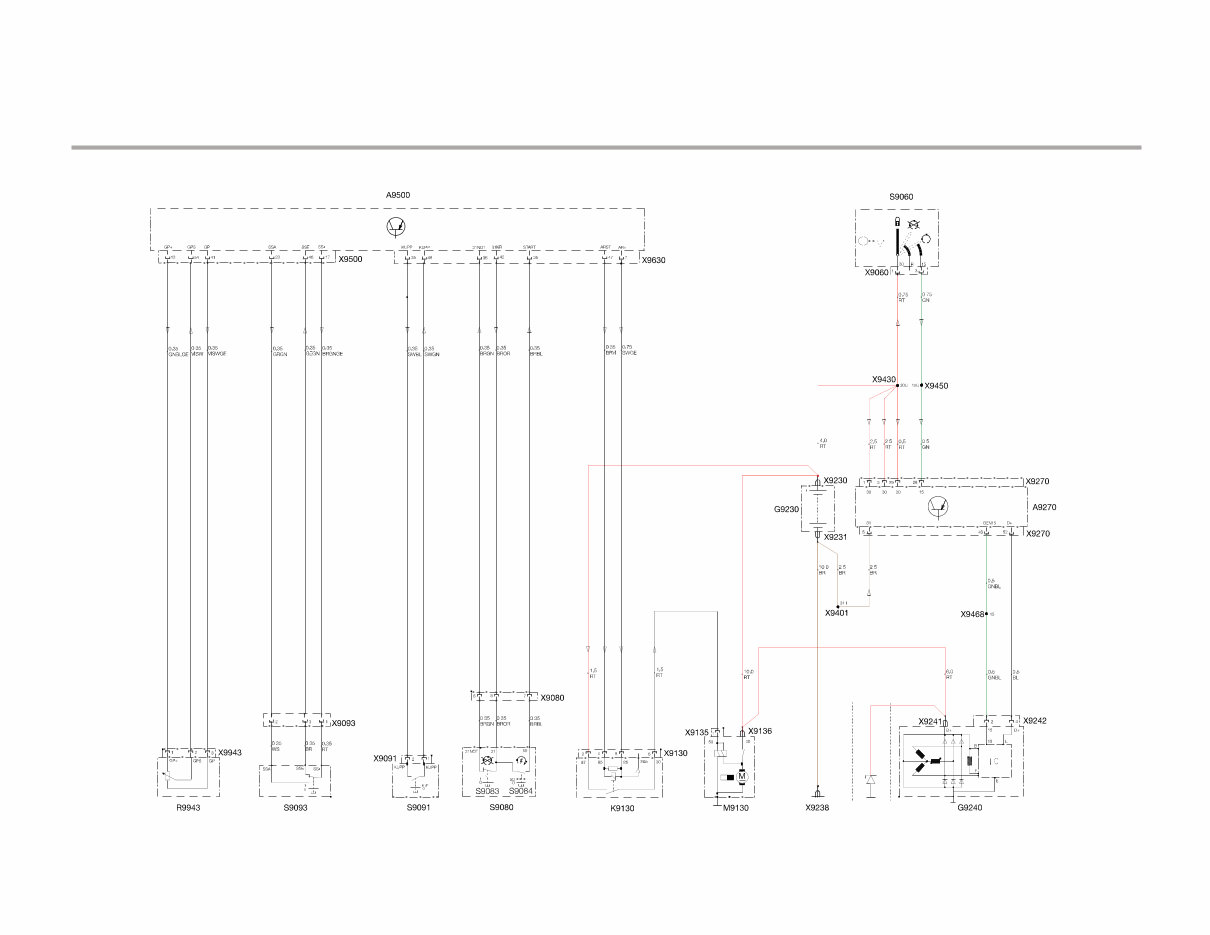
Wiring - 13/14 R 1200 GS I-Cluster w/out I ABS (Schematic VI) R 1200 GS Sock et/Heated Handgrips/ Diagnosis Plug/O ptional Accessory Sock et (Schematic VII) Ignition Switch Ignition Switch Right Multifunction Switch ZFE Control Module Battery (L) Heated Handgrips (R) O ptional Accessory Socket Accessory Socket Diagnostic Connector BMS K Control Module I ABS Control Modulator Battery ZFE Control Module I-Cluster Left Multifunction Switch Fuel Level Sensor Speed Sensor Alternator R 1200 GS Introduction
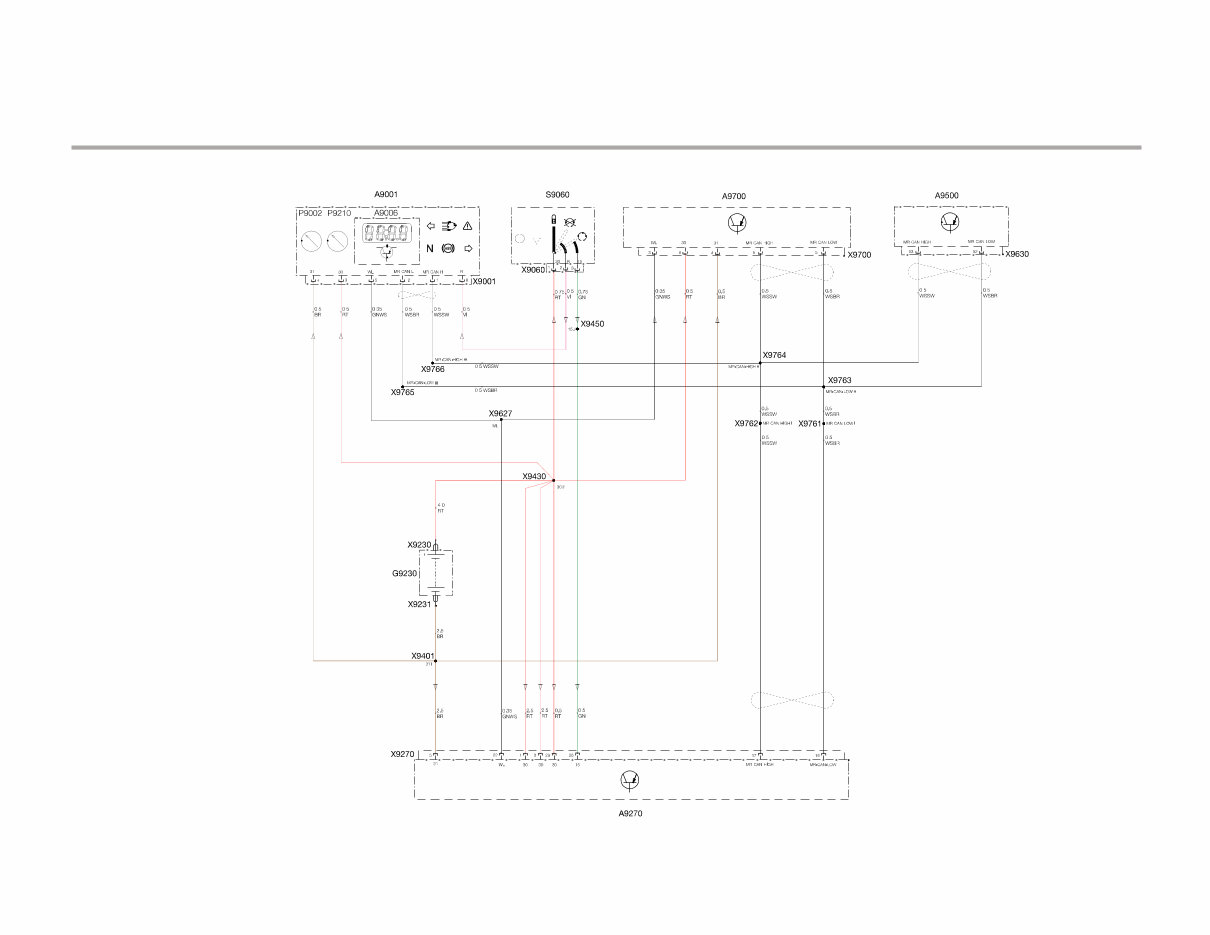
Wiring - 15/16 R 1200 GS Anti Thef t Alarm System (DW A VI) (Schematic VIII) ZFE Control Module DWA V I (Anti Theft System Control Module) Battery I Cluster Ignition Switch BMS K Control Module R 1200 GS Introduction
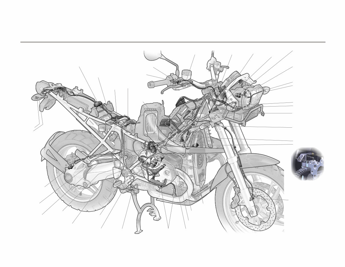
Wiring - 17/18 R 1200 GS Electrical Component Locations Diagram I R 1200 GS Introduction H ea dligh t a nd C onnector E 9 010, X 9 010 - L ow B ea m E 9 011 - H igh B ea m E 9 012 E WS Ring A ntenna L 9 553, X 9 553 F ront B ra k e Sw itch S9 051, X 9 051 Ignition Sw itch S9 060, X 9 060 H orn H 9 150, X 9 150 P a rk ing L igh t & C onnector E 9 015, X 9 018 L eft F ront B link er L igh t H 9 030 - X 9 031 (-) - X 9 032 (+ ) Righ t F ront B link er L igh t H 9 040 - X 9 041 (-) - X 9 042 (+ ) Righ t Rea r B link er H 9 045 - X 9 047 (+ ) - X 9 046 (-) F ront A B S Wh eel Sp eed Sens or H a rnes s C onn. X 9 19 3 E ngine O il Tem p Sens or B 9 562, X 9 562 E ngine Sp eed/Ref Sens or -X 9 326 (connector) -B 9 326 (s ens or) F ront Wh eel Sp eed Sens or B 9 19 3 O x y gen Sens or 1 B 9 69 0, X 9 69 0 Rea r B ra k e Sw itch S9 052 C am s h a ft P os ition Sens or B 9 531 C am s h a ft P os ition Sens or C onnector X 9 531 C y linder H ea d Tem p Sens or 1 B 9 739 C y linder H ea d Tem p Sens or 1 C onn., X 9 739 Idle Sp eed Step p er M otor 1 M 9 552, X 9 552 F uel Injector 1 Y 9 601, X 9 601 Rea r Wh eel Sp eed Sens or, B 9 19 4 Rea r B ra k e Sw itch H a rnes s C onn X 9 052 Righ t M ultifunction Sw itch S9 080, X 9 080 Sta rter Rela y, K 9 130, X 9 130 Rea r A B S Wh eel Sp eed Sens or H a rnes s C onn. X 9 59 0 D ia gnos tic C onnector X 9 59 0 Righ t H ea ted Grip R9 9 32, X 9 9 32 I A B S C ontrol M odula tor A 9 19 0, X 9 19 0 Ignition C oils Ground X 9 512 K nock Sens or 1 B 9 325, X 9 325 M a in Ignition C oil 1 T9 506, X 9 506 A ux ilia ry Ignition C oil 1 T9 517, X 9 517
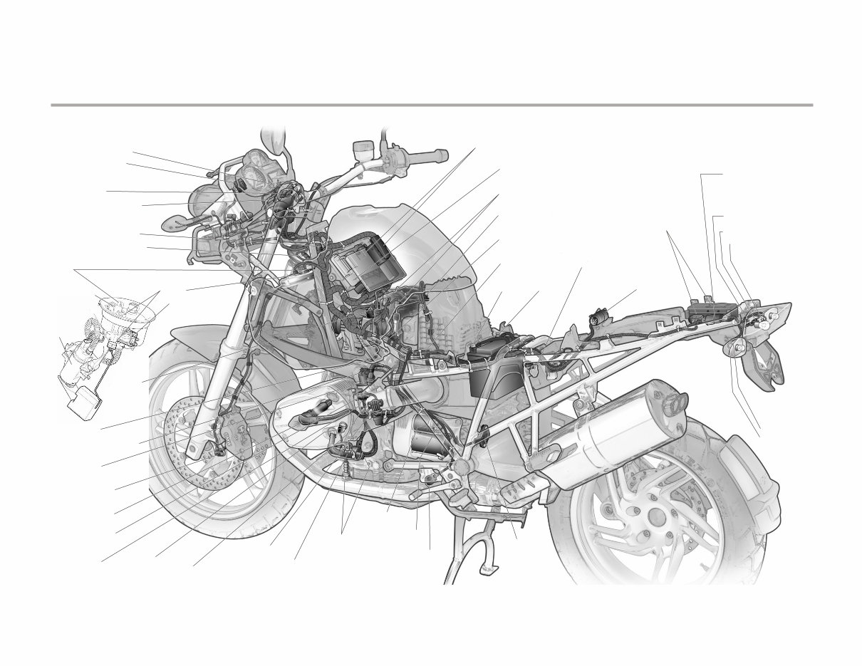
Wiring - 19/20 R 1200 GS Electrical Component Locations Diagram II R 1200 GS Introduction I Cluster A9001 X9001 Clutch Switch S9091 X9091 Horn H9150 X9157 Left Multifunction Switch S9070 X9070 Left Heated Grip R9931 X9931 Accessory Connector (Opt) X9349 Fuel Pump System X9100 Fuel Lev el Sensor X9220 B9220 DWA V I Alarm Module A9700, X9700 Taillight/Blinker Harness Connector X9340 Battery G9230 X9231(-), X9230 (+) Standard Accessory Socket X9321 Diagnostic Connector X9590 Ev aporativ e Purge V alv e Y9572, X9572 Side Stand Switch Connector X9093 Intake Air Temp Sensor B9550, X9550 I ABS Brake Fluid Lev el Switches and connectors Front: S9063, X9063 - Rear: S9064, X9064 BMS K Module and Connectors (b eneath Z FE) A9270, X9270 Z FE Module and Connector A9500, X9500, X9630 Fuel Pump Driv er Module A9100 Fuel Pump Motor M9100 Alternator G9240 X9241 X9242 Ground X9238 Idle Speed Stepper Motor 2 M9579, X9579 Fuel Injector 2 Y9602, X9602 Front Wheel Speed Sensor B9193 Main Ignition Coil 2 T9507, X9507 Cylinder Head Temp Sensor 2 T9507, X9507 Ignition Coils Ground X9514 Throttle Potentiometer R9570, X9570 Knock Sensor 2 B9584, X9584 Oil Pressure Switch S9095, X9095 Auxiliary Ignition Coil 2 T9518, X9518 Oxygen Sensor 2 B9738, X9738 Side Stand Switch S9093 Starter M9130, X9135, KL50 Starter M9130, X9136, KL30 Gearb ox Position Sensor R9943, X9943 Left Rear Blinker H9035 - X9036 (-) - X9037 (+) Rear Light Assemb ly E9340 - Taillight fillament E9013 - Connector X9014 - Brake light filament H9050 - Connector X9054 - Ground X9013
2013-2016 BMW R 1200 GS Electrical Wiring Diagrams Manual
The 2013-2016 BMW R 1200 GS Electrical Wiring Diagrams Manual is a vital resource for technicians and enthusiasts working on the electrical systems of this iconic adventure motorcycle. It provides detailed and precise wiring diagrams covering every circuit, from the ignition and lighting systems to advanced electronics and control units.
Each diagram is clearly labeled and structured to help you trace electrical pathways, identify connections, and troubleshoot issues with accuracy. Whether you’re diagnosing a fault or performing repairs, this manual offers the technical clarity needed to handle the intricate electrical systems found in the R 1200 GS.
In a digital format for easy access, this manual allows you to quickly reference wiring schematics whether you're in the garage or on the road. It's an indispensable tool for ensuring the electrical integrity and reliability of your 2013-2016 BMW R 1200 GS, supporting everything from routine maintenance to complex repairs.
Printable: Yes Language: English Compatibility: Pretty much any electronic device, incl. PC & Mac computers, Android and Apple smartphones & tablet, etc. Requirements: Adobe Reader (free)
Recently Viewed
5,521,897Happy Clients
2,594,462eManuals
1,120,453Trusted Sellers
15Years in Business
Price:
Actual Price:
2013-2016 BMW R 1200 GS Electrical Wiring Diagrams Manual