

Aprilia SR 50 Factory Service Repair Manual
What's Included?
Fast Download Speeds
Online & Offline Access
Access PDF Contents & Bookmarks
Full Search Facility
Print one or all pages of your manual
Service and repair manual
SR 50 -
964X
aprilia part # 8140222
1
SR 50
-
&/2%7/2$
– This manual contains information covering normal
servicing procedures.
– The information and illustrations contained in this man-
ual are current as of the manual’s publication. Since
aprilia s.p.a. strives to always improve the quality and
usefulness of its vehicles, changes may be made to the
vehicles at any time. Thus, it is imperative that users
of this manual understand that some information may
be out of date for some vehicles. Be sure that the in-
formation in this manual applies to the vehicle that you
are servicing before you begin any service operations.
– This publication is intended for aprilia dealers and their
trained and qualified mechanics. The description of
many service and repair operations is intentionally
omitted, as it is assumed that the users of this manual
have basic mechanical training, basic knowledge of the
procedures regarding motor vehicle repair, and have
available to them all current information published by
aprilia concerning the vehicle. Without these things,
the repair or servicing of the vehicle could be affected
and could lead to a dangerous condition or accident for
the servicing mechanic or the operator.
This manual does not describe all of the procedures
necessary to repair and service the vehicle in detail.
Therefore, it is important to be particularly careful in or-
der to avoid any damage to the vehicle, its parts, or to
cause injury to the mechanic or the rider.
Changes in the technical specifications and servicing
procedures that become necessary as a result of
changes to aprilia vehicles will be documented and
distributed to all aprilia dealers. Therefore, it is neces-
sary that the latest aprilia information be kept available
to the servicing mechanics.
If you have questions regarding repair and servicing
procedures, contact the aprilia Consumer Service
(A.C.S.). A.C.S. technical counselors will be able to
assist you with any problems that you might face.
For further information refer to:
– ENGINE SERVICE AND REPAIR MANUAL # 921
(I-UK-F-D-E);
– ENGINE SPARE PARTS CATALOGUE # 715;
– ENGINE SPARE PARTS CATALOGUE 1 # 716;
– “CHASSIS PARTS” SPARE PARTS CATALOGUE
# 515V.
– “CHASSIS PARTS” SPARE PARTS CATALOGUE
1 # 516V.
aprilia s.p.a. reserves the right to modify any of its models
in any manner at any time.
This manual is protected by copyright in all countries. Re-
production by any means, print or electronic, is prohibited.
The mention of products or services supplied by entities
other than aprilia is made for information purposes only.
aprilia is not responsible for the performance or use of
any product not specifically recommended or endorsed by
aprilia.
First edition: july 1999
Second edition:
Reprint: june 2000
Produced and printed by:
editing division
Soave (VERONA) - Italy
Tel. +39 - 045 76 11 911
Fax +39 - 045 76 12 241
E-mail: customer@stp.it
www.stp.it
On behalf of:
aprilia Consumer Service s.p.a.
via Noalese, 156 - 30036 Santa Maria di Sala (VE) - Italia
Tel. +39 - 041 57 86 101
Fax +39 - 041 57 86 100
www.aprilia.com
).42/$5#4)/.
This manual is divided into sections, chapters and para-
graphs, by subject. The procedures described are laid out
in single operation, and each operation is indicated by a
◆
.
The numbered parts shown in the figures are identified in the
text with the number in parentheses or with the symbol repre-
senting them.
Example: (the following text is generic and does not refer to
this specific vehicle):
3!&%497!2.).'3
Throughout this manual, you will see the following sym-
bols:
aWARNING
When you find this symbol on the vehicle or in the ve-
hicle, this indicates that a potential for serious per-
sonal injury or death exists. Failure to follow this
warning may result in serious risk of personal injury
or death, of the mechanic working on the vehicle, the
operator of the vehicle, or the general public. It also
indicates that serious and permanent damage to the
vehicle is possible.
aCAUTION
This statement indicates a potential hazard which
may result in some personal injury, or damage to the
vehicle.
NOTE The word “NOTE” in this manual precedes im-
portant information or instructions to which special atten-
tion must be given.
section
chapter
safety
warning
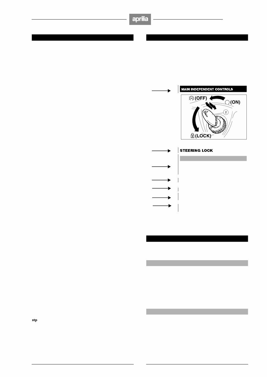
aWARNING
Never turn the key to position “s” while
the vehicle is being operated. If you do
so, you will lose control of the vehicle,
and a crash will ensue.
paragraph
OPERATION
operation
To lock the steering:
◆
Turn the handlebar completely to the left.
position (2)
◆
Turn the key (2) to position “m” (OFF)
and press it.
symbol “s”
◆
Release the key and rotate it to position “ s”
(LOCK).
◆
Remove the key.

2
SR 50
-
'%.%2!,3!&%4925,%3
#!2"/.-/./8)$%
If it is necessary to let the engine run in order to carry out
some work, make sure that the area in which you are op-
erating is properly ventilated. Never run the engine in en-
closed spaces.
If it is necessary to work indoors, use an exhaust evacua-
tion system.
aWARNING
The exhaust fumes contain carbon monoxide, a poi-
sonous gas that can cause loss of consciousness
and even death.
Run the engine in an open area or, if it is necessary to
work indoors, use an exhaust evacuation system.
'!3/,).%
Work in a well ventilated area. Keep cigarettes, flames or
sparks away from the work area and from the place where
gasoline is stored.
aWARNING
Gasoline is extremely flammable and becomes explo-
sive under certain conditions.
KEEP AWAY FROM CHILDREN.
(/4#/-0/.%.43
aWARNING
The engine and the components of the exhaust sys-
tem become very hot and remain hot for some time
after the engine has been stopped. Before handling
these components, wear insulating gloves or wait un-
til the engine and the exhaust system have cooled
down.
53%$%.').%/),
aWARNING
Use latex gloves for the maintenance operations that
require contact with used oil. Used engine oil may
cause skin cancer if repeatedly left in contact with
the skin for prolonged periods. Although this is un-
likely unless you handle used oil on a daily basis, it is
advisable to thoroughly wash your hands with soap
and water after handling used oil.
KEEP AWAY FROM CHILDREN.
"2!+%&,5)$
aCAUTION
The brake fluid can damage painted, plastic or rubber
parts. When performing maintenance operations on
the braking system, put a clean shop towel on these
parts.
Always wear goggles when servicing the brake sys-
tem with brake fluid. Brake fluid is extremely de-
structive to your eyes. If you should accidentally get
brake fluid in your eyes, flush immediately with a
large quantity of cool clear water and seek profes-
sional medical assistance immediately.
KEEP AWAY FROM CHILDREN.
#//,!.4
In certain conditions, the ethylene glycol contained in the
engine coolant is flammable: its flame is invisible, but you
can be burned anyway.
aWARNING
Avoid spilling the engine coolant on the exhaust sys-
tem or on the engine components. They may be hot
enough to cause the coolant to ignite and burn with-
out a visible flame.
The coolant (ethylene glycol) can cause skin irritation
and is poisonous if swallowed.
Engine coolant is extremely attractive to animals and
pets, as well as being extremely toxic to them. Do not
leave coolant in an open container where animals
may be able to drink it.
KEEP AWAY FROM CHILDREN.
Do not remove the radiator cap when the engine is
hot. The coolant is under pressure and may cause
burns.
"!44%29(9$2/'%.'!3!.$
%,%#42/,94%
aWARNING
The battery gives off explosive gases; keep ciga-
rettes, flames and sparks away from the battery. Pro-
vide adequate ventilation when operating or recharg-
ing the battery.
The battery contains sulphuric acid (electrolyte).
Contact with the skin or the eyes may cause serious
burns.

3
SR 50
-
Always wear tight fitting goggles and protective
clothing when handling battery electrolyte. It is par-
ticularly important for you to protect your eyes, since
even a minuscule amount of battery acid can destroy
your vision. Should you accidentally get even the
smallest amount of battery acid on your skin or eyes,
immediately flush with large quantities of clear cool
water and immediately seek professional medical at-
tention.
The electrolyte is poisonous.
If the electrolyte is accidentally swallowed, drink
large quantities of water or milk and then milk of
magnesia or vegetable oil. Seek professional medical
attention immediately.
KEEP AWAY FROM CHILDREN.
02%#!54)/.3
!.$'%.%2!,).&/2-!4)/.3
Follow with care these recommendations when repairing,
disassembling and reassembling the vehicle.
aWARNING
The use of naked flames is forbidden for any type of
operation.
Before commencing any service or inspection opera-
tion on the vehicle, switch off the engine and remove
the key, wait until the engine and the exhaust system
have cooled down and, if possible, raise the vehicle
with the suitable equipment onto firm flat ground.
The brakes also get quite hot in operation. Be sure
that the brakes have cooled thoroughly before begin-
ning any service operations.
In order to avoid burns, be careful not to touch any
parts of the engine or exhaust systems which have
not cooled down completely.
Avoid the temptation to hold any hardware or other
part of the vehicle in your mouth while working on
the motorscooter.
No part of the motorscooter is edible and some of the
coatings, plastics, and platings, etc. are noxious if
not outright toxic.
If not expressly described, the reassembly of the
units is carried out by reversing the order of opera-
tions.
Handle fuel with the greatest caution. See gasoline
warning above.
Never use fuel as a solvent for cleaning the vehicle.
Disconnect the negative cable (–) from the battery
when electric welding.
When two or more persons are working together,
make sure that each is working in safe conditions.
Be sure that all the mechanics working on any one
vehicle are thoroughly briefed as what each will be
doing, and insure that one mechanic is responsible
for insuring that all safety related items, such as
tightening torques, are properly considered.
BEFORE DISASSEMBLY
– Remove any dirt, mud, dust and foreign matters from
the vehicle before disassembling the components.
– Use, when necessary, the special tools designed for
this vehicle.
DISASSEMBLING THE COMPONENTS
– Before disconnecting the joints (pipes, cables, etc.),
mark the positions on all of them and mark them with
different distinguishing signs.
Each piece must be marked clearly, in order not to
have problems during installation.
– Clean and wash carefully any disassembled parts with
low inflammability detergents.
– Keep the parts that are used in pairs together, since
they have adapted to each other following the normal
wear. Some components must be used together or re-
placed completely.
– Keep away from heat sources.
REASSEMBLING THE COMPONENTS
aCAUTION
Never use a circlip twice. When a circlip is removed,
it must be replaced with a new one.
When assembling a new circlip be careful not to
stretch its ends more than strictly necessary to put it
on the shaft.
After installing a circlip, make sure that it is com-
pletely and firmly inserted in its seat.
Do not use compressed air to clean the bearings.
NOTE The bearings must rotate freely, without halting
or noise otherwise they must be replaced.
– Use only original aprilia SPARE PARTS.
– Use the recommended lubricants.
– Always lubricate parts before reassembly.
– When tightening screws, nuts, and bolts, start with the
largest diameter fasteners. When several fasteners
are arranged in a pattern, start with the innermost fas-
teners, and tighten diagonally across the pattern.
Tighten each fastener successively before applying the
final tightening torque.
– Always replace gaskets, grommets, circlips, O-rings
and split pins (cotter pins) with new ones.
Before assembling, clean all mating surfaces carefully,
removing all traces of the old gasket and gasket seal-
ing compound. Also carefully clean any oil seal you
plan to reuse. It is recommended that all oil seals be
replaced each time they are disassembled. Gaskets
should never be reused.
Apply a thin film of lithium based grease to all oil seals
before assembling.
Install oil seals and bearings with the identification
mark or serial number facing outward (visible).
Copiously lubricate bearings before installation and be-
fore assembly.
– Make sure that each component has been reassem-
bled correctly.
– After any repair or periodic maintenance operation is
carried out, the vehicle must be test ridden in an area
away from traffic and other hazards.
4
SR 50
-
(/74/53%
9/523%26)#%!.$2%0!)2-!.5!,
ADVICE FOR CONSULTATION
– This manual is divided into chapters, each one of which
corresponds to a category of main components. To
consult them, see the general index, p. 8 (TABLE OF
CONTENTS).
– If not expressly indicated otherwise, for the reassembly
of the units repeat the disassembly operations in re-
verse order.
– The terms “right” and “left” are referred to the rider
seated on the vehicle in the normal riding position.
– For normal maintenance operations and for the use of
the vehicle, consult the “USE AND MAINTENANCE”
manual.
The operations preceded by this symbol must be
repeated on the opposite side of the vehicle.
NOTE When asking your Dealer for spare parts, specify
the spare parts code indicated on the SPARE PARTS
IDENTIFICATION LABEL.
Write down the identification code in the space here be-
low, in order to remember it also in case of loss or deteri-
oration of the label.
The label is stuck on the right beam of the frame; to be
able to read it, remove the right inspection cover, see
p. 20 (REMOVING THE RIGHT AND LEFT INSPECTION
COVERS).
In this manual the various versions are indicated by the
following symbols:
&
optional
1
liquid-cooled version
3
drum brake version
VERSION:
I
Italy
V
Poland
U
United Kingdom
%
Israel
A
Austria
K
South Korea
P
Portugal
M
Malaysia
"
Finland
R
Chile
B
Belgium
Q
Bermuda
D
Germany
-
United States of America
F
France
^
Australia
E
Spain
Í
Brazil
G
Greece
°
South Africa
O
Holland
Î
New Zealand
C
Switzerland
[
Canada
Denmark
`
Croatia
J
Japan
Ñ
Slovenia
S
Singapore
★
5
SR 50
-
%,%#42)#!,#/..%#4/23
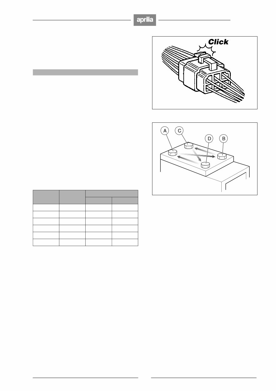
The electrical connectors must be disconnected as fol-
lows. Failure to follow these procedures will irreparably
damage the connector and wiring.
◆
Press in the click tab.
aCAUTION
Do not pull the cables to disconnect the two connec-
tors.
◆
Grasp the two connectors and disconnect them by
pulling in opposite directions.
◆
If dirt, rust, dust, or moisture is seen on the connector,
blow out the connector with air.
◆
Make sure that the cables are correctly crimped to the
terminals positioned inside the connectors.
NOTE The two halves of the connector fit together
properly in only one orientation. Ensure that the connec-
tor is properly aligned before attempting to assemble it.
◆
Press the connectors firmly together, listening for the
typical “click” sound for those connectors provided with
a click tab. Ensure that both halves of the connectors
are firmly pressed together.
4)'(4%.).'4/215%3
The table below shows tightening torques for screws and
bolts with metric ISO threads, as is used in this vehicle.
These are general values to be used if no specific value is
given in this manual or other aprilia service literature.
For specific fasteners, see p. 11 (TIGHTENING TOR-
QUES). If not otherwise indicated, the tightening torques
shown should be used for clean and dry threads, at room
temperature
NOTE To avoid damage to the threads, tighten screws
and bolts as follows:
◆
Run up the fasteners finger tight.
◆
Applying half the prescribed tightening torque, tighten
the fasteners that are diametrically opposite each oth-
er: (A) and (B); (C) and (D).
◆
Repeat, applying the prescribed tightening torque.
NOTE In this way the pressure exerted by the fasten-
ing elements will be uniformly distributed on the joint sur-
face.
Screw or
bolt thread
Spanner
Tightening torque
ftlb (Nm)
M 6 10 4.34 6
M 8 12 10.84 15
M 10 14 21.70 30
M 12 17 39.79 55
M 14 19 61.49 85
M 16 22 94.03 130
6
SR 50
-
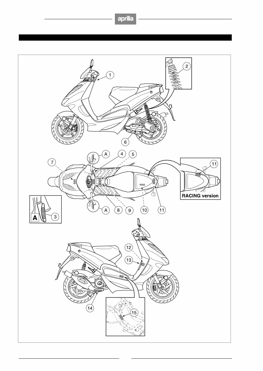
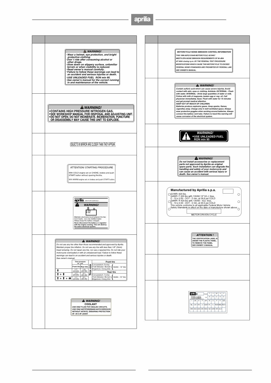
0/3)4)/./&4(%7!2.).'!$(%3)6%,!"%,3
7
SR 50
-
Ref. Description
1
2
3
4
5
6
7
8
9
10
11
12
13
14 Muffler stamping.
15
Ref. Description

8
SR 50
-
4!",%/&#/.4%.43
FOREWORD ............................................................................................ 1
INTRODUCTION ...................................................................................... 1
SAFETY WARNINGS............................................................................... 1
GENERAL SAFETY RULES .................................................................... 2
CARBON MONOXIDE.............................................................................. 2
GASOLINE ............................................................................................... 2
HOT COMPONENTS ............................................................................... 2
USED ENGINE OIL .................................................................................. 2
BRAKE FLUID .......................................................................................... 2
COOLANT ................................................................................................ 2
BATTERY HYDROGEN GAS AND ELECTROLYTE ............................... 2
PRECAUTIONS
AND GENERAL INFORMATIONS ........................................................... 3
BEFORE DISASSEMBLY ........................................................................ 3
DISASSEMBLING THE COMPONENTS ................................................. 3
REASSEMBLING THE COMPONENTS .................................................. 3
HOW TO USE
YOUR SERVICE AND REPAIR MANUAL ............................................... 4
ELECTRICAL CONNECTORS................................................................. 5
TIGHTENING TORQUES......................................................................... 5
POSITION OF THE WARNING ADHESIVE LABELS ............................. 6
TECHNICAL DATA................................................................................... 9
TIGHTENING TORQUES....................................................................... 11
LUBRICANT CHART .............................................................................. 11
TROUBLESHOOTING ........................................................................... 12
REGULAR SERVICE INTERVALS CHART .......................................... 14
IDENTIFICATION DATA........................................................................ 15
ARRANGEMENT
OF THE MAIN ELEMENTS.................................................................... 15
ARRANGEMENT OF THE INSTRUMENTS .......................................... 16
INSTRUMENTS AND INDICATORS ..................................................... 16
THROTTLE ............................................................................................ 16
CHECKING THE OPERATION
OF THE THROTTLE CONTROL ............................................................ 16
IDLING ADJUSTMENT .......................................................................... 17
ADJUSTING THE THROTTLE CONTROL ............................................ 18
FAIRINGS .............................................................................................. 19
REMOVING
THE PASSENGER GRAB HANDLE ...................................................... 19
REMOVING THE NUMBER PLATE-HOLDER....................................... 19
REMOVING THE LOWER GUARD
OF THE REAR PART OF THE FAIRING ............................................... 19
REMOVING THE REAR PART OF THE FAIRING ................................ 19
REMOVING THE RIGHT AND LEFT INSPECTION COVERS .............. 20
REMOVING THE LOWER SHIELD COVER .......................................... 20
REMOVING
THE COVER SUPPORT ELEMENT ..................................................... 21
REMOVING THE FRONT COVER........................................................ 21
REMOVING THE BATTERY / TOOL KIT COMPARTMENT COVER... 21
REMOVING
THE FRONT INNER SHIELD ................................................................. 22
REMOVING
THE REAR-VIEW MIRRORS ................................................................. 22
REMOVING THE FOOTBOARD ............................................................ 23
REMOVING THE FRONT MUDGUARD ................................................ 23
REMOVING THE LOWER HANDLEBAR COVER ................................. 24
PARTIAL REMOVAL OF THE UPPER HANDLEBAR COVER.............. 24
REMOVING THE CRASH
HELMET COMPARTMENT complete with saddle ................................. 25
REMOVING THE FRONT SHIELD COVER........................................... 25
REMOVING THE REAR MUDGUARD................................................... 26
INSTALLING THE REAR MUDGUARD EXTENSION .......................... 27
REMOVING THE COVER
OF THE REAR PART OF THE FAIRING ............................................... 27
REMOVING THE FRONT OUTER SHIELD ........................................... 28
REMOVING THE LOWER SHIELD........................................................ 28
FUEL TANK ........................................................................................... 29
FUEL ...................................................................................................... 29
CHECKING THE FUEL VALVE.............................................................. 30
DRAINING THE FUEL TANK ................................................................. 30
REMOVING THE FUEL VALVE ............................................................. 31
CHECKING THE FUEL LEVEL GAUGE UNIT....................................... 32
REMOVING THE FUEL LEVEL GAUGE UNIT ...................................... 32
REMOVING THE COMPLETE FUEL TANK .......................................... 32
2 STROKE OIL TANK............................................................................ 33
CHECKING............................................................................................. 33
DRAINING .............................................................................................. 33
REMOVAL .............................................................................................. 33
BLEEDING THE 2 STROKE OIL TANK ................................................. 34
COOLING SYSTEM 1 ....................................................................... 35
COOLANT 1....................................................................................... 35
CHECKING THE COOLANT LEVEL
AND TOPPING UP 1 ......................................................................... 36
DRAINING THE COOLANT SYSTEM 1 ............................................ 37
CHANGING THE COOLANT 1 .......................................................... 38
BLEEDING THE COOLANT SYSTEM 1 ........................................... 39
REMOVING THE RADIATOR 1......................................................... 40
REMOVING THE COOLANT PUMP 1 .............................................. 40
REMOVING THE EXPANSION TANK 1............................................ 41
REMOVING THE COOLANT
TEMPERATURE TERMISTOR 1....................................................... 41
BULBS ................................................................................................... 42
HEADLIGHT........................................................................................... 42
ADJUSTING THE HEADLIGHT
BEAM VERTICALLY ............................................................................. 42
ADJUSTING THE HEADLIGHT
BEAM HORIZONTALLY ........................................................................ 43
CHANGING THE HEADLIGHT BULBS ................................................ 44
REMOVING THE HEADLIGHT .............................................................. 45
FRONT AND REAR
DIRECTION INDICATORS .................................................................... 45
CHANGING THE BULB ......................................................................... 45
REAR LIGHT.......................................................................................... 46
CHANGING THE BULBS ....................................................................... 46
REMOVING THE REAR LIGHT ............................................................. 46
CHANGING THE LICENSE PLATE BULB ............................................ 47
DASHBOARD ........................................................................................ 47
CHANGING THE BULBS ....................................................................... 47
REMOVING THE COMPLETE DASHBOARD ....................................... 48
REMOVING THE DASHBOARD GLASS............................................... 48
ELECTRIC CONTROL SUPPORTS...................................................... 48
REMOVING THE HANDLEBAR CONTROLS........................................ 48
BRAKES ................................................................................................ 49
DISC BRAKES....................................................................................... 50
FRONT AND REAR BRAKE ................................................................. 50
CHECKING ............................................................................................ 51
TOPPING UP ......................................................................................... 51
REAR DRUM BRAKE 3 ................................................................... 53
FRONT WHEEL ..................................................................................... 54
DISASSEMBLY ...................................................................................... 54
CHECKING ............................................................................................ 55
REASSEMBLY ....................................................................................... 55
REAR WHEEL ....................................................................................... 57
DISASSEMBLY ...................................................................................... 57
GREASING
THE REAR BRAKE CAM PIN 3....................................................... 58
BRAKE CALIPERS ............................................................................... 59
REMOVING THE FRONT BRAKE CALIPER......................................... 59
REMOVING THE REAR BRAKE CALIPER ........................................... 60
BRAKE PADS........................................................................................ 61
CHECKING WEAR OF THE BRAKE PADS ......................................... 61
CHANGING THE BRAKE PADS............................................................ 61
BLEEDING THE BRAKING SYSTEM................................................... 62
BRAKE SHOES 3 ............................................................................. 63
CHECKING THE SHOE WEAR 3...................................................... 63
CHECKING THE THICKNESS
OF THE FRICTION MATERIAL 3...................................................... 64
REPLACING THE SHOES 3 ............................................................. 64
TRANSMISSION.................................................................................... 65
CHECKING THE TRANSMISSION OIL LEVEL..................................... 65
CHANGING THE TRANSMISSION OIL................................................. 65
CHECKING THE ENGINE FULCRUM AXIS ......................................... 66
WHEELS / TIRES .................................................................................. 66
INSPECTING THE WHEELS ................................................................. 66
TIRES..................................................................................................... 67
TIRE PRESSURE .................................................................................. 68
FORK HEAD .......................................................................................... 69
CHECKING THE STEERING ................................................................ 69
ADJUSTING THE BEARING PLAY ....................................................... 69
REMOVING THE FORK HEAD BEARINGS .......................................... 70
FRONT FORK........................................................................................ 71
CHECKING THE FORK OIL LEVEL ...................................................... 71
REMOVING THE COMPLETE FORK.................................................... 71
REMOVING THE LOWER FORK LEG
(with installed fork) .............................................................................. 72
DISASSEMBLING THE LOWER FORK LEG ....................................... 72
REAR SUSPENSION............................................................................. 73
REMOVAL.............................................................................................. 73
EXHAUST SILENCER ........................................................................... 73
DISASSEMBLY ...................................................................................... 73
AIR CLEANER....................................................................................... 74
REMOVAL.............................................................................................. 74
CLEANING THE AIR FILTER ................................................................ 74
IGNITION SWITCH / STEERING LOCK................................................ 74
REMOVAL.............................................................................................. 74
BATTERY............................................................................................... 75
BATTERY STORAGE ........................................................................... 76
CHECKING AND CLEANING
THE TERMINALS .................................................................................. 76
REMOVING THE BATTERY ................................................................. 76
CHECKING THE ELECTROLYTE LEVEL ............................................. 77
RECHARGING THE BATTERY ............................................................. 77
INSTALLING THE BATTERY................................................................. 77
ENGINE.................................................................................................. 78
REMOVING THE ENGINE FROM THE FRAME ................................... 78
ENGINE 1
(liquid-cooled version) ......................................................................... 80
REMOVING
THE ENGINE FROM THE FRAME 1................................................ 80
ENGINE MOUNTING BUSHINGS ......................................................... 81
REMOVAL.............................................................................................. 81
ELECTICAL SYSTEM ........................................................................... 82
CONTENTS............................................................................................ 82
CHECKING
THE THERMISTOR OPERATION 1 ................................................. 94
9
SR 50
-
4%#(.)#!,$!4!
DIMENSIONS
Max. length 70.47 in (1,790 mm)
Max. length (with rear mudguard extension) 74.02 in (1,880 mm)
Max. width 28.35 in (720 mm)
Max. height (front part of the fairing included) 45.67 in (1,160 mm)
Seat height 32.68 in (830 mm)
Wheelbase 49.21 in (1,250 mm)
Min. ground clearance 6.30 in (160 mm)
Curb weight 207.23 lb (94 kg)
Curb weight 1 218. 26 lb (99 kg)
ENGINE
Type 2-stroke with controlled ignition
Number of cylinders 1
Total displacement 3.01 cu in (49.26 cm )
Bore / stroke 1.57 in / 1.54 in (40 mm / 39.2 mm)
Compression ratio 12.5 ± 0.5:1
Starting electric + kick starter
Engine idling rpm 1800 ± 100 rpm
Clutch automatic centrifugal dry clutch
Change gear Automatic stepless variator
Cooling with forced air
Cooling 1
liquid cooled
CAPACITY
Fuel (reserve included) 2.11 US gal (8 L )
Fuel reserve 0.53 US gal (2 L )
Transmission oil 3.72 US fl oz (110 cm )
2 stroke oil (reserve included) 1.69 US qt (1.6 L )
2 stroke oil reserve 0.53 US qt (0.5 L )
Coolant 1 0.32 US gal (1.2 L )
(50% water + 50% antifreeze with ethylene glycol)
Seats 2
Vehicle max. load
(driver+passenger+luggage) 396.83 lb (180 kg)
Gross weight limit (GVWR) (*) 620 lb (281 kg)
Permissible wheel loads (GAWR) (*)
– front 200 lb (91 kg)
– rear 420 lb (190 kg)
(*) These two weights: Gross Vehicle Weight Rating (GVWR) and Gross Axle Vehicle Weight Rating (GAWR); are stamped on the certi-
fication plate positioned on the front part of the frame, see pag. 15 (IDENTIFICATION DATA) (FRAME NUMBER).
TRANSMISSION
Speed change gear automatic and stepless
Primary V-belt
Ratios minimum for stepless change: 2.6
maximum for stepless change: 0.862
Secondary with gears
You're Reading a Preview
What's Included?
Fast Download Speeds
Online & Offline Access
Access PDF Contents & Bookmarks
Full Search Facility
Print one or all pages of your manual
$36.99
Viewed 28 Times Today


Secure transaction
What's Included?
Fast Download Speeds
Online & Offline Access
Access PDF Contents & Bookmarks
Full Search Facility
Print one or all pages of your manual
$36.99
The Aprilia SR 50 Factory Service Repair Manual is a comprehensive guide that includes a maintenance schedule and detailed repair procedures. Whether you are a professional mechanic or a DIY enthusiast, this manual provides the necessary information to address issues in a cost-effective manner.
- Important Information
- Engine removal
- Engine Disassembly
- Electric starter
- Cylinder head
- Cylinder Removal
- Piston removal
- Ignition unit
- Oil pump
- Clutch
- Water pump
- Crankshaft
- INDIVIDUAL COMPONENT MAINTENANCE
- ENGINE REASSEMBLY
- ENGINE INSTALLATION
This manual is available in English and can be printed. It comes in a file format compatible with both WINDOWS and MAC operating systems. To access the manual, you will need Adobe Reader. Simply click on the instant payment button to complete your purchase using PayPal or a credit card, and receive the download link immediately.


