Operator’s Manual Garden Tractors S, T and V Series Models S150H, S1500H, T1600H, T1800H, T1600-4WD, T25-4WD and V25-50HE 366007300 B Downloaded from www.Manualslib.com manuals search engine
Safety Instructions Page 1 Training 1. Read the instructions carefully. Be familiar with controls and the use of equipment. 2. Never allow children or people unfamiliar with these instructions to operate the mower. 3. Never mow while people, especially children or pets, are nearby. 4. The operator or user is responsible for accidents or hazards occurring to other people or their property. 5. Do not carry passengers. 6. All drivers should seek to obtain professional and practical instruction. In addition the following should be noted: • The need for care and concentration when working with this machine. • Control of a tractor sliding on a slope; control will not be regained by applying the brake. • The main reasons for loss of control are: i. Insufficient wheel grip ii. Driving too fast iii. Operating on steep slopes (max 15º) iv. Incorrect load distribution Preparation 1. Check that the machine complies with all applicable regulations, including those in force when used on the public highway. 2. When mowing, always wear substantial footwear and long trousers. Do not operate when barefoot or with sandals. 3. Thoroughly inspect the area where the tractor is to be used and remove all stones, sticks, wires and bones or any other foreign objects. 4. WARNING – petrol is highly flammable: • Store fuel in containers specifically designed for this purpose. • Re-fuel outdoors only and do not smoke while refuelling. • Add fuel before starting the engine. Never remove the cap from the fuel tank or add diesel while the engine is running or when engine is hot. • If fuel is spilled, do not attempt to start the engine but move the machine away from the area of spillage and avoid creating any source of ignition until petrol or diesel vapours have dissipated. • Replace the fuel cap securely. 5. Replace faulty silencers. 6. Before using, always inspect to see that the blades, bolts and cutter assembly are not worn or damaged. 7. Check the condition of the tyres and ensure that they are inflated to the correct pressures (refer to pages 25-26). This is particularly important if the machine is to be taken on the public highway. 8. Check that the mower is in good working order, paying special attention to brakes, steering, water and oil. 9. Check that all linkages, connections and pivot nuts are secure and that the wheel nuts are tightened correctly. Contents Safety Instructions Page 1 Operating Instructions Page 2 Controls Page 3 – 8 Powered Grass Collector Page 9 – 10 Using your Tractor Page 11 Cutter decks Page 12 – 13 Routine maintenance Page 14 – 16 Troubleshooting: Cutting Page 17 Cutter Levelling Page 18 – 19 Grass Collecting Page 20 Tyres & Wheels Page 21 Starting & Running Page 22 Electrics Page 23 – 24 Specifications Page 25 – 26 Personal Service Record Page 27 Certificate of Conformity Page 28 Please Note: The information contained on this, and the following pages is given on the understanding that Westwood accepts no responsibility for work carried out by a customer or for any damage thus caused, whether or not the service instructions have been misunderstood. To be sure that your warranty terms are not breached, service work should only be carried out by your dealer. Downloaded from www.Manualslib.com manuals search engine
Page 2 Operating Instructions Safety 1. Read the instructions carefully. Be familiar with controls and the use of equipment. 2. Do not operate the engine in a confined space where dangerous fumes can collect. 3. Mow only in daylight or in very good artificial light. 4. Before starting the engine, disengage blade and attachment drives and make sure handbrake is engaged. 5. Take care on slopes – maximum 15º. 6. Remember, there is no such thing as a ‘safe slope’. Travel on grass slopes requires particular care to guard against overturning: • Do not stop or start suddenly when going up or downhill. • Engage drive slowly. Always keep the machine in drive when travelling up or down a slope. • Machine speed should be kept low on slopes and in tight turns. • Stay alert for humps and hollows and other hidden hazards. • Avoid mowing across the face of a slope. 7. Watch out for traffic when crossing or working near roadways. 8. Stop the blades rotating before crossing roadways. 9. When using the machine, never direct discharge or material towards bystanders or allow anyone near the machine while in operation. 10. Never operate the mower with defective guards, shields or without protective safety devices in place and in good working order. 11. Do not change governor settings to increase the speed of the engine. Operating an engine at excessive speed increases the risk of injury. 12. Before leaving the operator’s position: • Disengage the drive to the cutter blades and attachments, then lower the attachments. • Apply the Parking Brake. • Stop the engine and remove the ignition key. 13. Always disengage drive to attachments, stop the engine and remove the ignition key before: • Cleaning blockages. • Checking, cleaning or working on the mower. • Refuelling. • Removing the Grass Collector. Also: • After striking a foreign object inspect the mower for damage and make any repairs before restarting the tractor. • If the machine starts to vibrate abnormally, check immediately and call your dealer if necessary. 14. Disengage drive to attachments when transporting or not in use. 15. Reduce the throttle setting during engine run-out. 16. Never work on the mower when the engine is running. Always: Use good common sense at all times and to ensure this tractor is safe and serviceable fit only original manufacturer’s supplied spares. • Inspect the area to be cut, note the position of any stumps, drain covers, bumps or depressions and avoid them to prevent damaging the blades. • Ensure the fuel tank is full before you start the machine. • ONLY use the specified fuel for your machine. • Disconnect both battery terminals before attempting any work in the engine compartment. Never: • Leave the tractor unattended and running. • Put hands near moving blades, belts or the Power Take- Off pulley while they are rotating. Powered Grass Collector (PGC) Collector Height Adjustment Lever Cutter Deck Anti-scalp Wheel PGC Net PGC Connection Lever Power Take-Off (PTO) Engage Lever Tractor Drive Pedals Downloaded from www.Manualslib.com manuals search engine
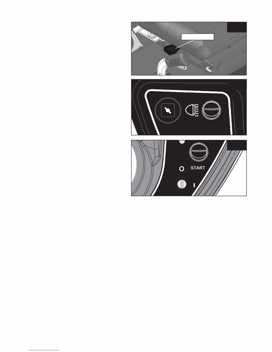
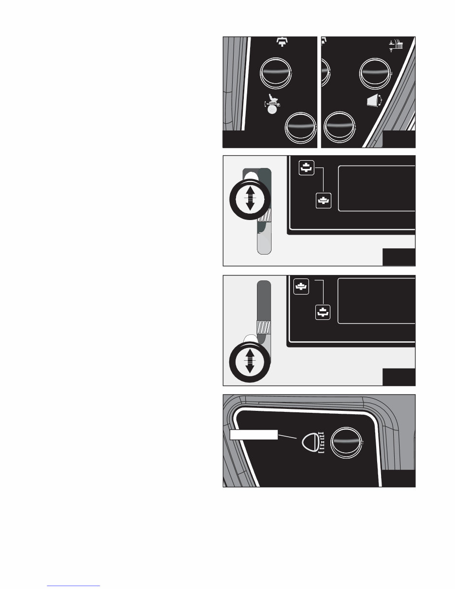
Page 3 Operating Instructions, Controls Seat Adjustment (Fig. 1) The seat on your tractor is adjustable forward and backward to suit the operator. Simply lift the seat latch at the side of the seat and slide the seat forward or backward as appropriate. Always ensure the seat is latched back into position before driving off. Choke (Fig. 2) An independent choke is fitted to some models. This choke should be used in conjunction with a fast throttle setting when starting the engine from cold. It should be cancelled as soon as possible. Do not use the choke when starting a warm engine. Ignition (Figs. 3, 6 & 11) The key start controls the ignition and the start button engages the starter. The engine cannot be started without the park brake being on; the “P” light (Fig. 11) indicates the brake is engaged (not applicable to the Mini). When starting your tractor from cold, turn the key to the I position. Once the cycle has finished press the start button to start the Tractor. Release the button when the engine starts. To stop the engine, turn the key to the left (having first switched off both the cutter and Power Take- off). To prevent unauthorised use, always remove the key after use. THE IGNITION MUST ALWAYS BE TURNED OFF AND LEFT FOR AT LEAST TWO SECONDS BEFORE THE TRACTOR CAN BE RE- STARTED. fig. 1 fig. 2 fig. 3 Seat Lever Downloaded from www.Manualslib.com manuals search engine
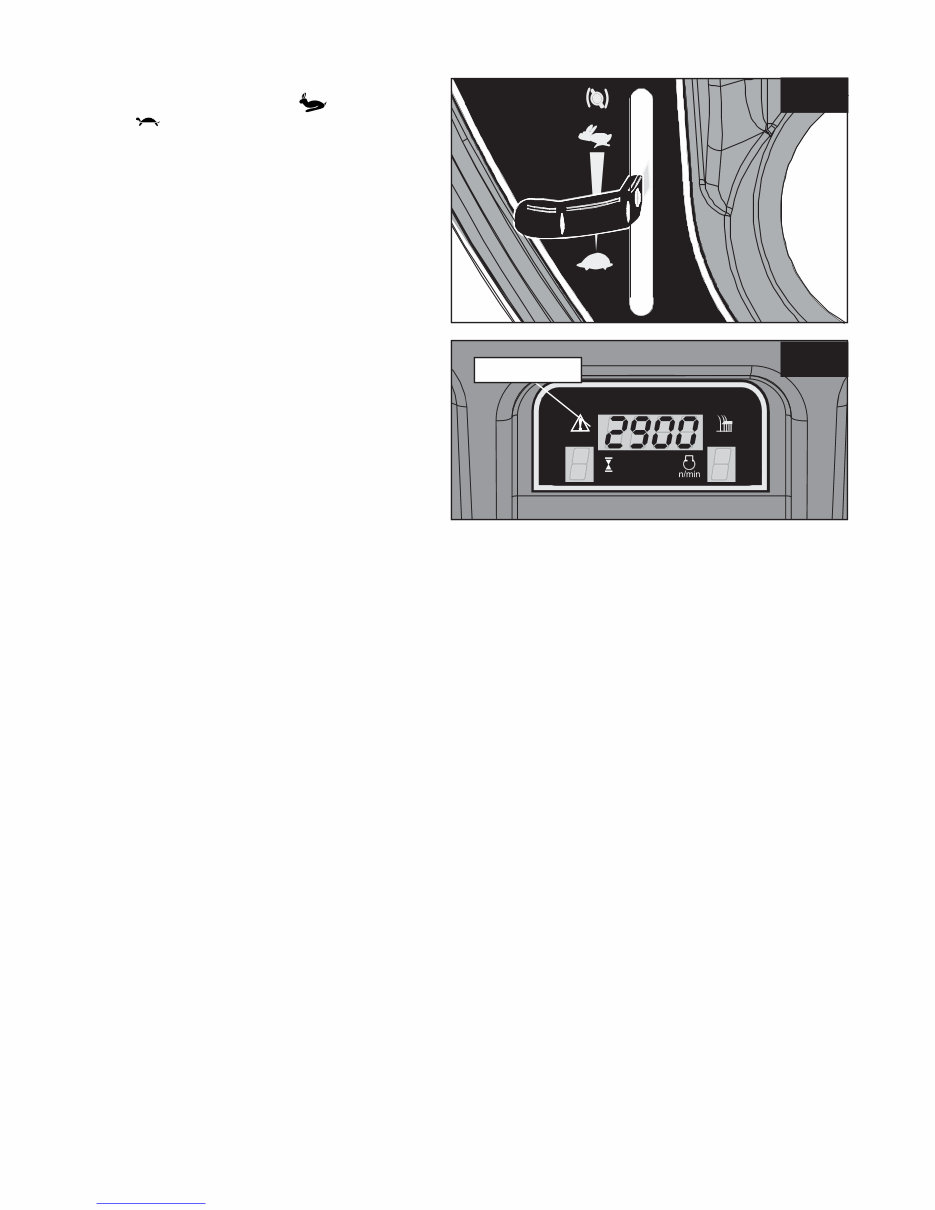
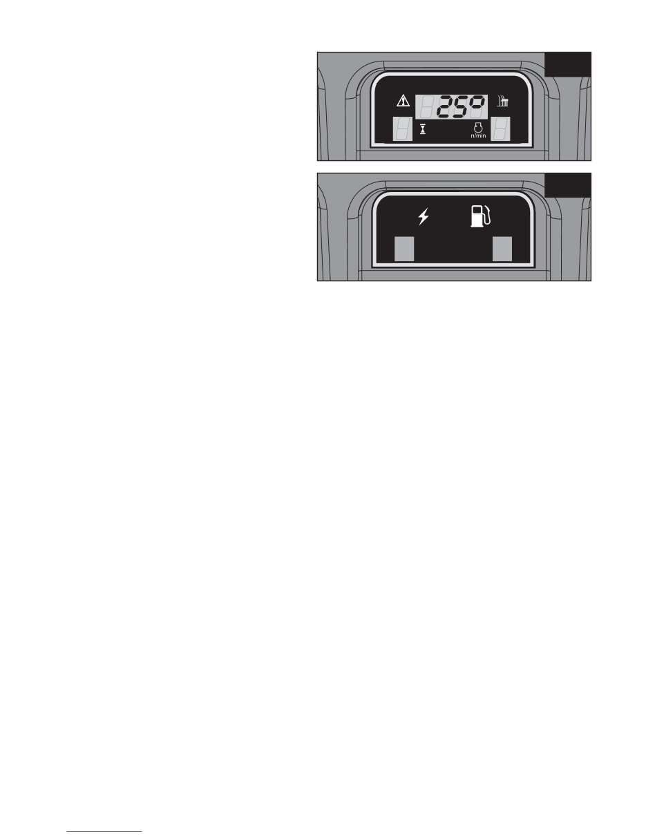
RPM Meter fig. 5 Operating Instructions, Controls Engine Speed Control (Fig. 4) The lever is pushed up for FAST ( ) and down for SLOW ( ). On some models the choke control is above the fast setting, a cold engine is started on the Choke setting, a warm one on the FAST setting. The Choke setting should be cancelled as soon as possible. The engine should be operated on the FAST setting at all times. RPM Meter (not applicable to Mini tractor) (Fig. 5) The RPM monitor on the electronic display indicates the engine speed. This feature should be used when the cutter deck is engaged and in conjunction with the forward speed. To ensure complete cutting and collection the engine speed should not be allowed to fall below 2600rpm, the display will flash should this happen. If, when in use, the display does flash indicating that the engine speed has dropped below 2600rpm, there are two options: a) Reduce forward speed b) Raise the cutting height. fig. 4 Page 4 Downloaded from www.Manualslib.com manuals search engine
Page 5 Operating Instructions, Controls Drive Controls (Fig. 6) The forward speed of the tractor is controlled by foot pedal ‘A’. Reversing is controlled by foot pedal ‘B’. Moving Off / Reversing (Figs. 6 & 7) To move off, ensure your feet are off pedals ‘A’ and ‘B’ and then release the parking brake by pushing the hand lever ‘C’ (Fig. 7) to the forward position. Now gently depress pedal ‘A’ and you will move off. The further you depress pedal ‘A’ the faster you will go. Its function is similar to that of a car accelerator except that it controls the hydrostatic transmission and does not affect the speed of the engine. To reverse simply depress pedal ‘B’ and the tractor will begin to reverse. As with the forward pedal, the speed of reversing is increased as the pedal is pushed further. Stopping To stop the tractor simply release either pedal ‘A’ or ‘B’ and the natural braking of the hydrostatic system will bring the tractor to a standstill. For smooth braking release either pedal gradually, for an emergency stop remove foot rapidly. Parking (Figs. 6 & 7) Remove your foot from pedals ‘A’ or ‘B’ (as you would to stop normally) and then simply pull the parking brake lever ‘C’ to the upright position - a ‘P’ will be indicated on the dashboard display (Page 6 Fig. 11). When you turn off the engine, the natural braking of the hydrostatic system will add to the effect of the brake. It’s like leaving your car in gear. Neutral Valve (Fig. 8) The natural braking of hydrostatic transmission means that it is not possible to easily push or freewheel the tractor. To disengage, first make certain that the machine is on a flat even surface. Release the parking brake by moving lever ‘C’ forward. Locate the Neutral Valve, situated on the back plate near the towing bracket. Engage by pulling out the lever. You will now be able to push the tractor at a speed not exceeding 2 mph. Make sure you disengage the Neutral Valve by pushing the lever back BEFORE starting your tractor. Differential Lock (where fitted) (Fig. 9) Your tractor may be fitted with a differential lock. This should only be used in situations where one wheel is slipping and the other is not. In a situation when one wheel starts to slip and extra traction is required release the forward pedal so the wheels stop going around, depress the Differential Lock pedal (Fig. 9 pedal D), and then the forward pedal slowly. The differential will lock both wheels to drive at the same speed. As soon as the differential lock is not required release the engage pedal ‘D’ and as soon as the wheels are rotating at the same speed and not under load (i.e. on a slope) the lock will automatically release. IMPORTANT – DO NOT ATTEMPT TO STEER THE TRACTOR WHEN THE DIFFERENTIAL LOCK IS ENGAGED. ALWAYS ENSURE THE DIFFERENTIAL LOCK IS RELEASED BEFORE MANOEUVRING IN A CLOSED AREA. Lever C Pedal A Pedal B Pedal D Neutral Valve fig. 6 fig. 7 fig. 8 fig. 9 Downloaded from www.Manualslib.com manuals search engine
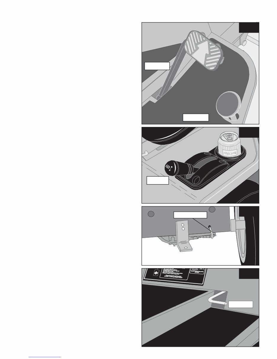
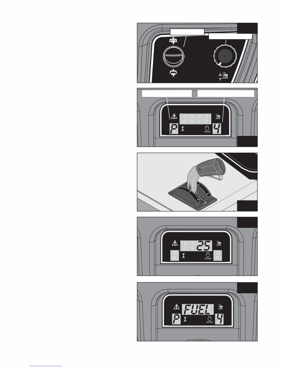
Page 6 Operating Instructions, Controls Cutter On/Off Switch (Figs. 10 & 11) The cutter switch controls the electromagnetic blade clutch. To switch the cutter on, push the switch and then release it, this will engage the cutter deck. To indicate that the Cutter Deck is engaged, the Cutter Deck Height Indicator will flash (Fig. 11). To stop the Cutter Deck, push the switch again. Although the Cutter Deck is automatically switched off when the engine is stopped or when the operator gets off the seat, it is not good practice to rely on these features, the Cutter Deck should always be switched OFF as soon as you have finished cutting and certainly BEFORE stopping the engine or getting off the tractor. The Cutter will only work whilst the operator is sat on the seat. NOTE: The headlights will flash whilst the Cutter Deck is running if they are not being used. If the headlights are in use they will not flash but function as normal. Electric Lifts (not applicable to Mini tractor) (Figs. 10 & 11) Electric deck height adjustment (where fitted) The cutting height is adjusted by turning the rotary switch anti-clockwise to lower the deck and clockwise to raise the deck (Fig. 10). The height indicator on the electronic display (Fig. 11) shows the deck position (0 – lowest to 9 – highest). To get the best from this refinement use it to continuously adjust cutting height to suit ground and grass conditions. Do not make downward adjustments on the move until you are familiar with the height control, this will avoid “scalping” the lawn. Manual Deck Lift (where fitted) (Fig. 12) Your tractor may be fitted with a manual deck lift. To operate, simply push the trigger in until the weight of the deck can be felt and pull back to the desired cutting height (numbered 1-9). To lower, hold the trigger in and push forward. Exercise caution when operating lift lever. Hour Meter (not applicable to Mini tractor) (Fig. 13) Your tractor is fitted with an hour meter to assist you in adhering to the recommended service intervals. The hour meter only operates whilst the engine is actually running. Clocked hours will show up on the RPM display prior to starting the engine. Recommended service intervals are shown on page 25. NOTE: 50 hours of mowing at 5 mph equates to 250 miles of grass cutting! Low Fuel Warning (not applicable to Mini tractor) (Fig. 14) When the tractor is low on fuel a warning will appear where the RPM display is saying ‘FUEL’, this is a warning to tell you to fill up again as the tractor is about to run out of petrol or diesel. Electric Deck Lift Park Brake Indicator Cutting Height Indicator fig. 10 fig. 11 fig. 12 fig. 13 fig. 14 Cutter On/Off Downloaded from www.Manualslib.com manuals search engine
Page 7 Operating Instructions, Controls Auxiliary Lift Switch (where fitted) (Fig. 15) Raising the Auxiliary (Grass Collector) Lift is achieved by pressing a switch (Fig. 15) on the dashboard – UP to raise, DOWN to lower. Emptying the Powered Grass Collector is achieved UP To engage the PTO drive, the PTO lever is lifted up and out of its locator and then moved to the left and released to find its own height. To disengage the PTO use. DO NOT PUT HANDS NEAR MOVING PULLEYS disengage. Always have this lever in the ‘disengaged’ Pressing the rocker switch turns ON the headlights. switch again. The headlights will not operate without Light Switch fig. 18 fig. 17a fig. 17 fig. 16 fig. 15 Auxiliary Lift Switch (where fitted) (Fig. 15) Raising the Auxiliary (Grass Collector) Lift is achieved by pressing a switch (Fig. 15) on the dashboard – UP to raise, DOWN to lower. Net Empty Switch (where fitted) (Fig. 16) Emptying the Powered Grass Collector is achieved by pressing a switch (Fig. 16) on the dashboard – UP to open, DOWN to close. Power Take-Off (Mini and S & T Series) (Fig. 17) To engage the PTO drive, the PTO lever is lifted up and out of its locator and then moved to the left and released to find its own height. To disengage the PTO pull the lever up and to the right. Always have this lever in the ‘disengaged’ position when it is not in use. DO NOT PUT HANDS NEAR MOVING PULLEYS AND BELTS. Power Take-Off (V Series) (Fig. 17a) To engage the PTO, push the lever down and to the left and release lever upwards. The PTO lever is pushed down and to the right into its locator to disengage. Always have this lever in the ‘disengaged’ position when it is not in use. DO NOT PUT HANDS NEAR MOVING PULLEYS AND BELTS. Lights (Fig. 18) Pressing the rocker switch turns ON the headlights. Turn the headlights OFF by pressing the rocker switch again. The headlights will not operate without the ignition switch turned on. Downloaded from www.Manualslib.com manuals search engine
fig. 18a fig. 18b Page 8 Operating Instructions, Controls Electronic Slope Alert (ESA) (not applicable to Mini tractor) (Figure 18a) Should your tractor be fitted with 4WD it will have ESA. This is set to an angle of 25° at the factory. If this angle is exceeded then the display will flash 25° and a warning siren will sound. The exceptional traction of 4WD will allow you to cut in very slippery conditions, and it also allows the tractor to ascend very steep slopes. If the slope alarm sounds DO NOT attempt to cut or drive at a greater angle than the one you are on. As all terrains and conditions vary, great care should be maintained when operating the tractor. DO NOT take the tractor into an area where it could become unstable. On no account should slopes steeper than 25° be driven on. Battery and Fuel (MIni tractor) (Figure 18b) The Mini has a simple dashboard arrangement. The two red filtered squares show the charge (Left hand) and the fuel level (right hand). When the ignition is turned on the charge light is lit. The only time the charge light goes off is when there is a failure with charging. If this happens you should ring your nearest dealer. When the fuel level is running low the fuel warning light will appear. The tractor will need to be refuelled A.S.A.P. Downloaded from www.Manualslib.com manuals search engine
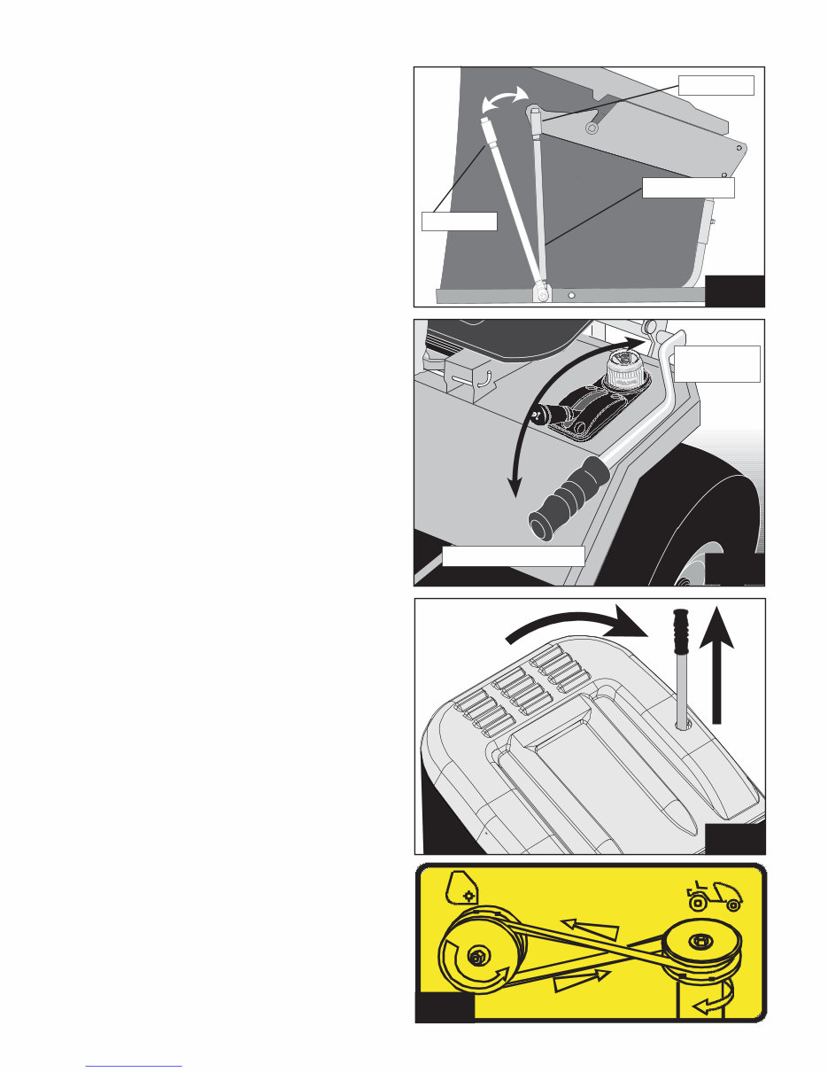
Operating Instructions, Powered Grass Collector Page 9 fig. 20 Net Rod Position X Position Y fig. 18c Transport Position Collecting Position fig. 19 fig. 19a Fitting the Net (Mini, S & T Series) (Fig. 18c) Fit the Net as shown in Figure 18c with the net rod in position ‘X’. To remove the net, release the net rod and secure in the removal position ‘Y’. Manual PGC Lift Lever (Fig. 19) Using the lever (figure 19) raise or lower the Powered Grass Collector to either the Transport position or the Collecting position. To Tip Cuttings (Mini, S & T Series) (Fig. 19a) First turn off the engine. When the collector is full, raise the collector to the transport position. Drive to your tipping area, reverse to the grass pile, and select neutral if the tractor is manual. Then extend the tipping lever and pull it towards the seating position. This pivots the collector and so empties the collector. Once the grass is off-loaded return the collector to the upright position and put the tipping lever in its original position. Installing the Drive Belt (Fig. 20) First turn off the engine. Place the drive belt over the PTO pulley of the Powered Grass Collector, and then feed it underneath the PTO flap. Then feed around the PTO pulley. Be sure that this is installed the right way round otherwise the brush will work in reverse and collection will be poor. Lock the Locating Lever over the Lift Arm Lugs (this also tightens the PTO Drive Belt). Rotate the Locking Clips over the Locating Lugs to securely lock the Powered Collector in place. To disconnect, reverse this procedure. ALWAYS CHECK BELT TENSION IS 19mm DEFLECTION AT 2KGs PRESSURE. Refer to page 15 for adjustment instructions. Downloaded from www.Manualslib.com manuals search engine
When it comes to maintaining and repairing lawnmower motors, having the right manual is essential for both professional mechanics and DIY enthusiasts. The Westwood Garden Tractors Owners Manual is a valuable resource for anyone looking to perform routine maintenance or repairs at home.
With its reliable design and simple construction, lawnmower motors are relatively easy to work with, making repairs quick and trouble-free for most home mechanics. Regular maintenance, including oil changes, spark plug replacements, and filter inspections, is crucial for ensuring the longevity and optimal performance of your lawnmower motor.
Having a quality service manual specific to your lawnmower motor is invaluable for identifying its parts and assisting you during routine maintenance. This manual contains 29 pages of essential information, allowing you to print only what you need. It covers a wide range of topics, including safety precautions, controls and switches, preparation, adjustments, service checklists, lubrication, maintenance, electrics, wiring diagrams, specifications, storage, powered grass collector, vacuum collector, and accessories.
By performing routine maintenance and occasional repairs at home, you not only save money but also gain a better understanding of your lawnmower motor's working components. This manual will be a valuable asset in prolonging the life of your lawnmower motor and ensuring its continued reliable use.