Turbo 400 Transmission Hydramatic Turbine 400 Service Manual
What's Included?
Lifetime Access
Fast Download Speeds
Online & Offline Access
Access PDF Contents & Bookmarks
Full Search Facility
Print one or all pages of your manual
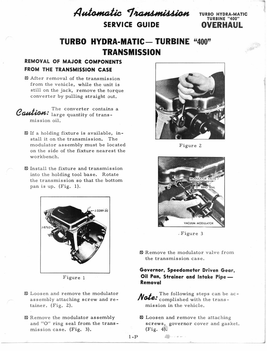
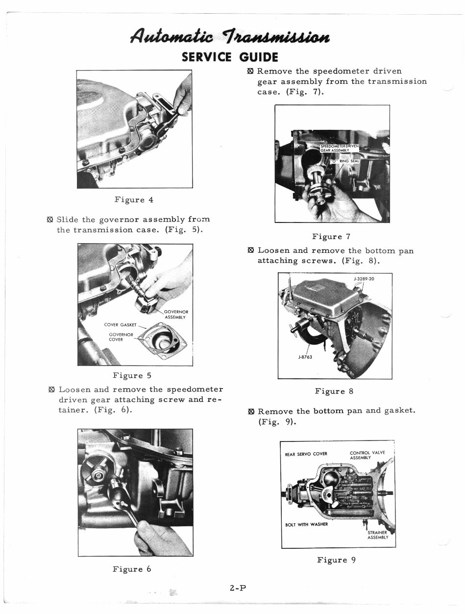
1/ uttUH4Uc <1-'KWJ~d44(,j~ SERVICE GUIDE TURBO HYDRA-MATIC TURBINE "400" OVERHAUL "400" Fig ur e 2 . Fig ure 3 Governor. Speedometer Driven Gear, Oil Pan. Strainer and Intake Pipe- Removal ~ Remo ve the modulator valve fro m the transm iss ion case. ~ After removal of the transmission from the vehi cl e, while the unit is still on the jack, remove the torque converter by pulling straight out. Figure I TURBO HYDRA-MATIC- TURBINE TRANSMISSION REM OVAL OF MAJOR COMPONENTS FROM THE TRANSMISSION CASE ~ Install the fix ture and transmission into the holdi ng tool base. Rotate the transmis sion so that the bottom pan is up. (Fig. I) . ~ If a holding fixt ur e is a vailable, in- stall it on the transmission. The modulator asse mbly must be located on the side of th e fixture nearest the workbench. e -- ~ · The converter contains a ~I,(J.H, : large quantity of trans- mission oil. ~ Loos en and re move the modulator assembly attac hing screw and re- tainer. (Fig. 2). AJ_ ~ • Th e followin g steps can be ac - /rCJ4,B. complish ed with the trans- mission in the vehicle . ~ Remove the modulator assembly and "0" ring seal from the trans- mission case . (Fig. 3). ~ Loosen and remov e the attachin g screws , governor cover and gasket. (Fig. 4). I-P
IIuttJ.lH4Uc <J.'UUlfJ4'If4d44Ci~ SERVICE GUIDE REAR SERVO COVER Figur e4 ~ Slide the governor assembly fr om the t ra nsmission case. (Fig. 5) . Fig ure 5 ~ Lo o se n and remov e the speedometer drive n gear att aching screw and re- tai n er. (Fig. 6). Figu re 6 2-P ~ Remove the speedome ter dr iven gear assembly from th e transmission case. (Fig. 7). Figure 7 ~ Loosen and remove th e bottom pan attaching screws. (Fi g. 8). Figure 8 ~ Remove the bottom pan and gasket . (Fig. 9) • .-------- ---- -----, I Figure 9
II~Uc ~~CH'IN<J44Cj~ SERVICE GUIDE TURBO HYDRA.MATle TURBINE "400" OVERHAUL ~ Remove the pump intake pipe and strainer ass embly. (Fig. 10). Figure 10 ~ Remove the intake p ipe to case "0" ring seaL Control Val ve Assembly. Governor Pipes and Detent Spring Assembly - Removal _ J. The foll owing steps can be ac- NCJ4,e: compli shed with the trans- mission in the vehicle. ~ Loosen and remove the control valve body attachi ng screws. Remove the control valv e body and detent roller and spring assembly. (Fig. 11). Fi gure 11 /'.J J. • Do not remove the solenoid / -- v (i"l44, t, fJ.ItJ : attac hing screws. ~ Remove the control valve body as- sembly and governor pipes. (Fig. 12). Figur e 12 eGMt. Use care that the manual t,Q.ItI,: valve doe s not fall out of the control valve assembly. ~ Remove the governor pipes from the control valve as sembly . (Fi g. 13 ). Figure 13 ~ Remove the control valve assemb ly to spacer gasket . (Fig . 14). Figu re 14 3-P
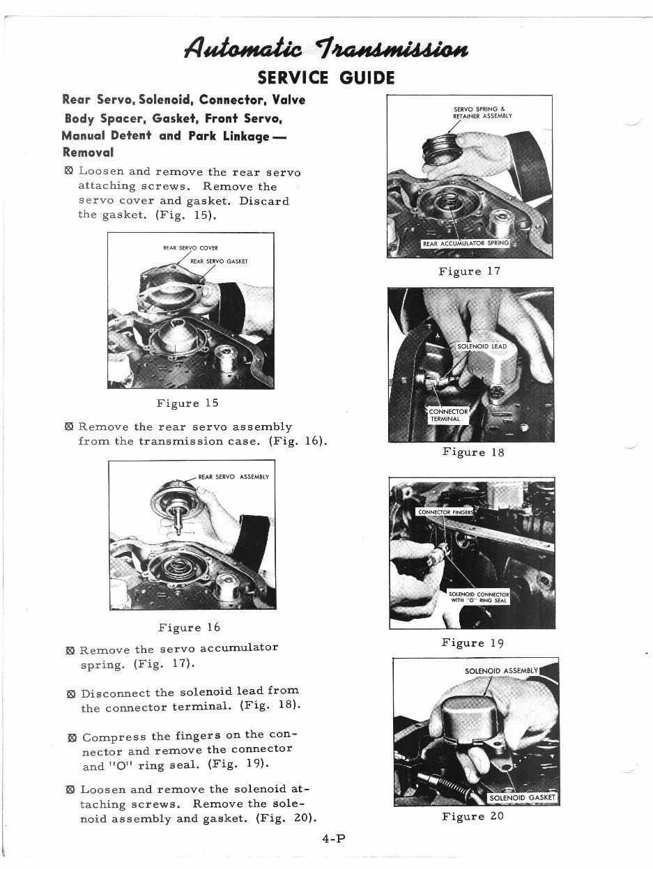
SERVO SPRING & RETAINER ASSEMBLY Figure 18 Figure 20 Figure 19 Figure 17 ~ Disconnect the solenoid lead from the connector terminal. (Fig. 18). Fig ure 15 ~ Compress the fingers on the con- nector and re m ov e the connector and "OIl ring sea l. (Fig. 19). ~ Loosen and re move the solenoid at- taching screws. Remove the sole- noid assembly a nd gasket. (Fig. 20). Fi gure 16 ~ Remove the ser vo accumulator spring. (Fig. 17 ) . REARSERVO COVER ~ Remove the re ar servo assembly from the trans mission case. (Fig. 16). ~ Loosen and re move the rear servo attaching screw s. Remove the servo cover an d gasket. Discard the gasket. ( Fi g. 15). lJid tuH4tk ~~ldMI~W#J SE RVICE GUIDE Rear Servo. Solenoid. Connector. Valve Body Spacer. Gasket. Front Servo. Manual Detent and Park Linkage- Removal 4-P
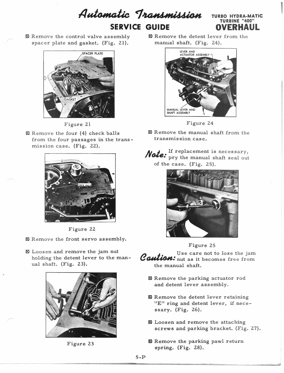
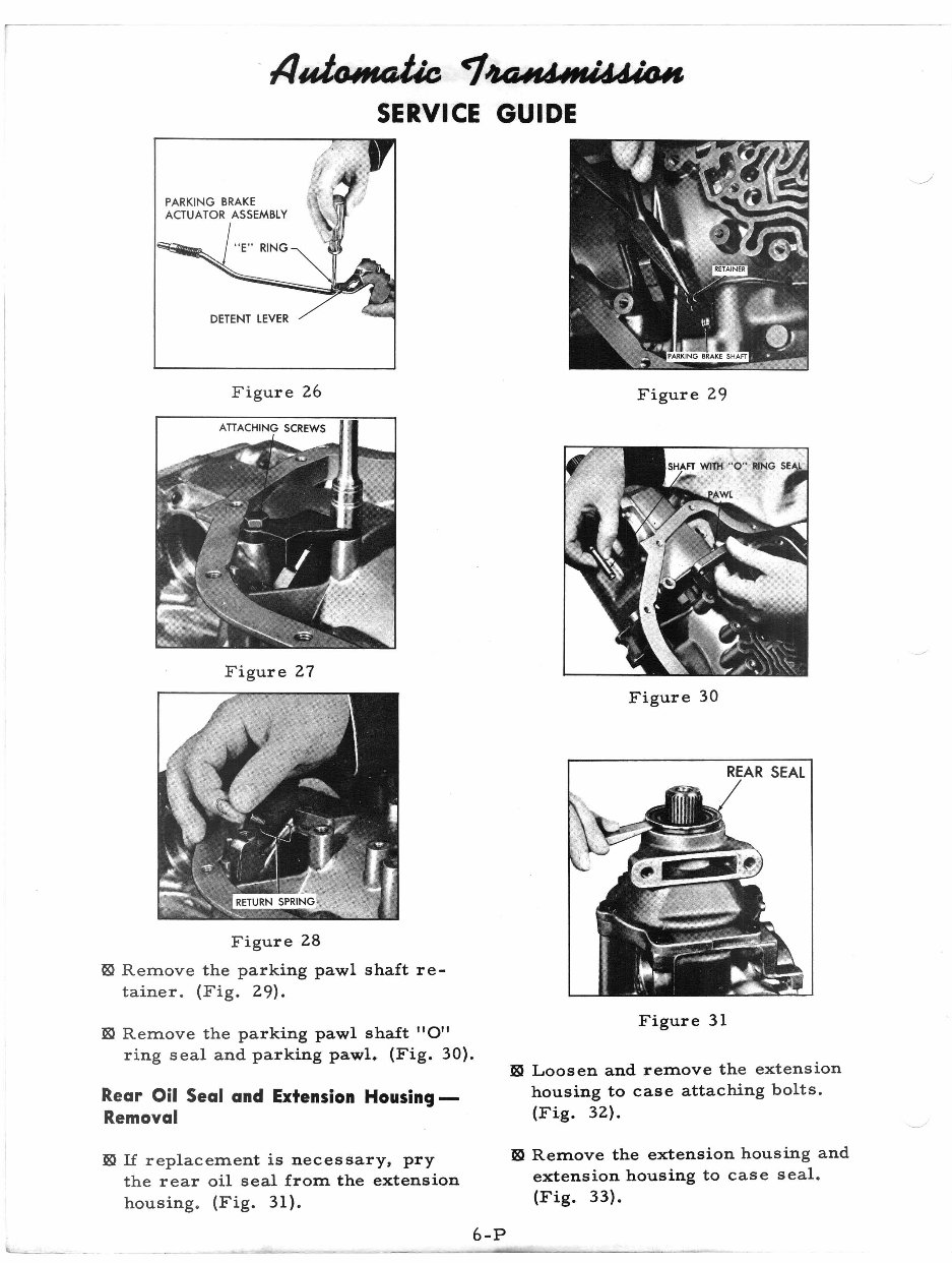
TURBO HYDRA.MATIC TURBINE "400" OVERHAUL • II~ e-t~fU'lUd44Ci1olf SERVICE GUIDE ~ Remove the control valve assembly spacer pl ate and gasket. (Fig. 21). ~ Remove the det ent lever from the manual shaft. (F ig. 24) . Fi gur e 21 ~ Remove the four (4) check balls from the fou r passages in the trans- mission case . (Fig. 22) . Figure 22 ~ R emove the front servo assembly. Figure 24 ~ Remove the manual shaft from the transmission case . Not If replacement is necessar y, e: pry the manu al shaft seal out of the case. (Fig . 25). ~ Loosen and remove the jam nut h olding t he detent lever to the man- ual shaft. (Fig. 23). Figure 25 e -__ .I. Use care no t to lose the jam Q,/44,I,fJ.#fI: nut as it be comes free from the manual shaft. Figure 23 l8J Remove the parking actuator rod and detent lever assembly. ~ Remove the det ent lever retaining "E'I ring and detent lever, if nece- ssary. (Fig . 26). ~ Loosen and remov e the attaching screws and parking bracket. (Fig . 27). ~ Remove the parking pawl return spring. (Fig. 28). 5-P
- IJ~ <7.~tI4I'N~1.II SERVICE GUIDE DETENT LEVE R Figur e 26 ATIACHI NG SCREWS Figu re 27 Figur e 28 ~ Remove the parking pawl shaft re- tainer. (Fig. 29). ~ Remove the parki ng pawl shaft "0" ring seal and pa rk in g pawL (Fig. 30). Rear Oil Seal and Extension Housing- Removal ~ If replacement is ne cessary, pry the rear oil seal f 'r orn the extension housing. (Fig. 31). 6-P Figure 29 Figure 30 REAR SEAL Figure 31 ~ Loosen and remove the extension housing to case attac hi ng bolts. (Fig. 32). m Remove the extensio n housing and extension housing to case seal. (Fig. 33).
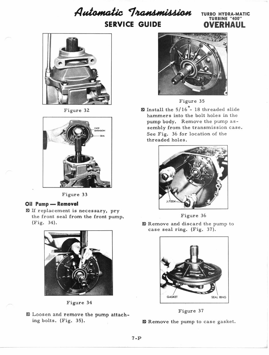
llui~ ~'UUlfJ4II'U~Jn SERVICE GUIDE TURBO HYDRA·MATIC TURBINE "400" OVERHAUL SEAL RING GASKET Figur e 35 I, ~ Install the 5/16 - 18 threa ded slide hammer s into the bolt hole s in the pump body . Re m ov e the p ump as - sembly from th e transm is sian case. See Fig. 36 for locatio n of the threaded hole s. Figure 36 ~ Remove and d is card the pump to case seal ring . (Fig . 37). F igure 32 Fi gure 33 Oil Pump - Removal ~ If replacement is neces sary, pry the front seal from the front pump. (F ig. 34). Figure 34 ~ Laos en and remove the pump attach- ing bolts. ( Fi g. 35). Fi gur e 37 ~ Remove the pump to cas e ga ske t. 7-P
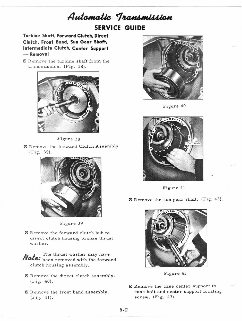
Figure 40 Figure 41 ~ Remove the sun gear sh af t. (Fig. 42 ). Fig ur e 38 ~ R emove the for ward Clutc hA ss embl y ( Fig . 39). llui~ <7.~~~ SERVICE GUIDE Turbine Shaft. Forward Clutch. Direct Clutch. Front Band. Sun Gear Shaft. Intermediate Clutch. Center Support - Removal ~ R emove the tur bi ne s haft from the transmission. (F i g. 38 ). Fi gur e 39 ~ Remove the for ward clutc hh ub to direct clutch housing bronze thrust washer. AJ_ ~ The thru st wa sh er may have .IJ0£8: been rem oved with the forward clutch housing ass embl y. ~ Remove the dir ect cl utch assembly . (Fig. 40). ~ Remove the fr ont b and assembly. (Fig. 41). Figure 42 ~ Remove the case c enter support to case bolt and center supp ort lo c ati ng screw. (Fig. 43) . 8-P
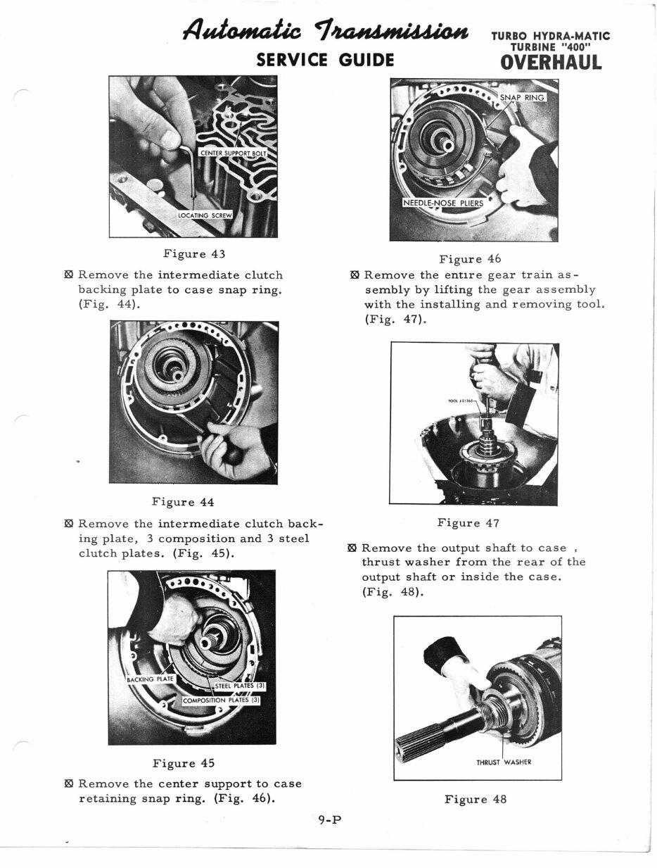
IItdtUH4tk et.~UWft~1IfU'I, SERVICE GUIDE TURBO HYDRA·MATIC TURBINE "400" OVERHAUL Figure 43 ~ Remove th e intermediate clutch backing plat e to case snap ring. (Fig. 44). Figure 44 ~ Remove the intermediate clutch back- ing plate, 3 composition and 3 steel clutch plates. (Fig. 45). Figure 45 ~ Remove th e center support to case retaining snap ring. (Fig . 46). 9-P Figure 46 ~ Remove the errti re gear train as- sembly by lifting the gear assembly with the installing and removing tool. (Fig. 47) . Figure 47 ~ Remove the output shalt to case , thrust washer fro m the rear of the output shalt or ins ide the case. (Fig. 48). Figure 48
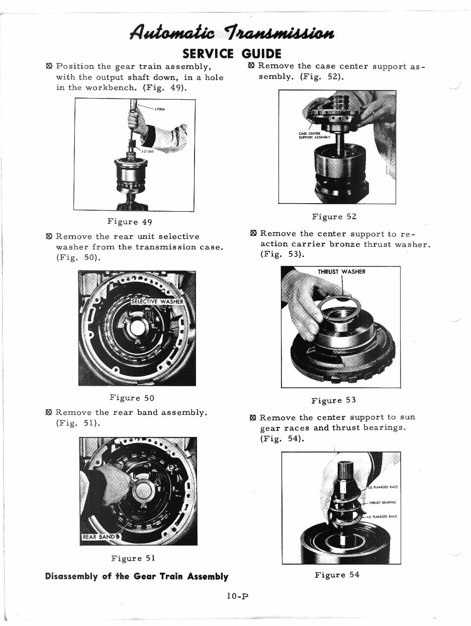
• II~ ~'UUt'44lf4id4«UI SERVICE GUIDE ~ Position th e gear t rain assembly , with the out put shal t down , in a hole in the workbe nch. (Fig. 49). Fi gur e 49 ~ Remove the rear unit se lec t ive washer from th e transmis si on case . (Fig. 50). ~ Remove the case center support as- sembly. (Fig. 52). Figure 52 ~ Remove the center support to re- action carrier bronz e th rust washer. (Fig. 53). Fi gure 50 ~ Remove the rear band assembly. (Fig. 51). F igure 51 Figure 53 ~ Remove the center support to sun gear races and thrus t bea rings. (Fig . 54). Disassembly of the Gear Train Assembly Figure 54 10-P
A fully text-searchable version of this manual is available for the TurboHydramatic / Turbine 400 transmission. It is designed to provide detailed technical information and reference, including a transmission identification chart and auto trans fundamentals. The manual also covers the disassembly and reassembly of the transmission, with easy-to-read exploded views for identification, careful disassembly, accurate adjustment, and correct repairs.
All sections are neatly organized in Adobe Acrobat, featuring clean, sharp images that are scalable to several times normal size. The manual includes crystal clear illustrations, specifications, lots of pictures, step-by-step instructions, and special tool info. It is designed for easy access - you can zoom in, print, save, and close it. No need to carry a bulky binder around; simply print the necessary pages as you need them.
Recently Viewed
5,521,897Happy Clients
2,594,462eManuals
1,120,453Trusted Sellers
15Years in Business
Price:
Actual Price:
Turbo 400 Transmission Hydramatic Turbine 400 Service Manual