

Meritor forward tandem drive axles maintenance service manual
What's Included?
Fast Download Speeds
Online & Offline Access
Access PDF Contents & Bookmarks
Full Search Facility
Print one or all pages of your manual
Maintenance Manual 5L
Single-Reduction Forward Differential
Carriers on Tandem and Tridem Axles
Revised 08-15

Service Notes
Information contained in this publication was in effect at the time the publication was
approved for printing and is subject to change without notice or liability. Meritor Heavy
Vehicle Systems, LLC, reserves the right to revise the information presented or to
discontinue the production of parts described at any time.
Meritor Maintenance Manual 5L (Revised 08-15)
About This Manual
This manual provides maintenance and service information for the
Meritor forward tandem drive axles, including the RT-140; -144;
-145; -149; -160; -169; RZ-166; -186 and -188 Series models.
Before You Begin
1. Read and understand all instructions and procedures before
you begin to service components.
2. Read and observe all Warning and Caution hazard alert
messages in this publication. They provide information that can
help prevent serious personal injury, damage to components,
or both.
3. Follow your company’s maintenance and service, installation,
and diagnostics guidelines.
4. Use special tools when required to help avoid serious personal
injury and damage to components.
Hazard Alert Messages and Torque
Symbols
WARNING
A Warning alerts you to an instruction or procedure that you
must follow exactly to avoid serious personal injury and
damage to components.
CAUTION
A Caution alerts you to an instruction or procedure that you
must follow exactly to avoid damage to components.
@ This symbol alerts you to tighten fasteners to a specified torque
value.
How to Obtain Additional Maintenance,
Service and Product Information
Visit Literature on Demand at meritor.com to access and order
additional information.
Contact the Meritor OnTrac™ Customer Call Center at
866-668-7221 (United States and Canada); 001-800-889-1834
(Mexico); or email OnTrac@meritor.com.
If Tools and Supplies are Specified in
This Manual
Contact Meritor’s Commercial Vehicle Aftermarket at
888-725-9355 to obtain Meritor tools and supplies.
SPX Kent-Moore, 28635 Mound Road, Warren, Michigan, 48092.
Call the company’s customer service center at 800-345-2233, or
visit their website at spxkentmoore.com.
Kiene Diesel Accessories, Inc., 325 S. Fairbanks Street, Addison, IL
60101. Call the company’s customer service center at
800-264-5950, or visit their website at kienediesel.com.
SPX/OTC Service Solutions, 655 Eisenhower Drive, Owatonna, MN
55060. Call the company’s customer service center at
800-533-6128, or visit their website at otctools.com.

pg. pg.
Contents
1 Section 1: Exploded Views
Single-Reduction Forward Differential Carrier
4 Section 2: Introduction
Description
Forward Tandem Axle
Axle Models Covered in This Manual
Optional Pressurized Lubrication System
Optional Driver-Controlled Main Differential Lock (DCDL)
5 Inter-Axle Main Differential (IAD)
Stall-Testing Can Damage a Drive Axle
Use of Traction Chains
Identification
Model Number
7 Section 3: Removal and Disassembly
Removal
Axle Shafts
Axle Shaft Removal Methods
9 Axle Shafts from the Axle Housing
10 Thru-Shaft
11 Differential Carrier from the Axle Housing
12 Disassembly
Thru-Shaft and Output Bearing Cage Assembly
13 Removal
Bearing Cone from the Thru-Shaft
Measure Ring Gear Backlash
14 Input Shaft and Inter-Axle Differential Assembly
16 Disassembly
Input Shaft, Bearing Cage, Oil Pump and Inter-Axle
Differential
19 Removal
Inter-Axle Differential Lock IAD Shift Unit
20 Driver-Controlled Main Differential Lock (DCDL)
Main Differential Case and Ring Gear Assembly
21 Disassembly
Main Differential Case and Ring Gear
22 Removal
Ring Gear from the Differential Case
23 Drive Pinion Assembly
Before You Work on a Differential Carrier
Assembly Procedures
25 Section 4: Prepare Parts for Assembly
Clean, Dry and Inspect Parts
Clean and Inspect Yokes
26 Clean Ground and Polished Parts
Clean Rough Parts
Clean Axle Assemblies
26 Drying Parts After Cleaning
Prevent Corrosion on Cleaned Parts
Inspect Parts
28 Repair or Replace Parts
Welding on Axle Housings
29 Do Not Bend or Straighten a Damaged Drive Axle Housing
Removing Fasteners Secured with Adhesive
30 New Fasteners with Pre-Applied Adhesive
Original or Used Fasteners
Meritor Specification 2297-T-4180 Adhesive in the
Differential Bearing Bores
Carrier-to-Housing Joint Sealing Procedure
32 General Yoke and U-Joint Reassembly
Identification
Gear Sets
33 Check for Mismatched Ratios on Tandem Axles
Hypoid Gear Set Ratios Listed on the Identification Tags
Rotate the Forward Drive Shaft to Check the Hypoid Gear
Set Ratio
34 Hypoid Gear Set Teeth Numbers Stamped on the Forward
and Rear Axle Drive Pinions
35 Verify the Actual Hypoid Gear Set Ratios
Inspection
Yoke
36 Tire Matching for Tandem and Tridem Axles
37 Section 5: Assembly and Installation
Installation
Installing the Drive Pinion and Adjusting Pinion Depth and
Preload
Adjustment
Shim Pack Thickness for a New Drive Pinion
38 Assembly
Drive Pinion Assembly
40 Installation
Drive Pinion Assembly
41 Adjustment
Drive Pinion Bearing Preload
45 Assembly
Main Differential and Ring Gear
47 Check the Rotating Resistance of the Differential Assembly
48 Installation
Main Differential Case and Ring Gear Assembly Into the
Carrier
50 Adjustment
Differential Bearings Preload
52 Ring Gear Runout
Ring Gear Backlash

Contents
pg. pg.
53 Gear Set Tooth Contact Patterns, Backlash
57 Installation
Thrust Screw (If Equipped)
Air Shift Unit for the Inter-Axle Differential Lock
59 Assembly
Input Shaft, Bearing Cage, Oil Pump and Inter-Axle
Differential
63 Installation
Input Shaft Assembly
64 Inspection
Adjust the Input Bearing End Play
67 Installation
Driver-Controlled Main Differential Lock
Output Bearings and Thru-Shaft
68 Inspection
Adjust the Output Bearing End Play
Installation
Unitized Pinion Seal
71 Installing a Multiple-Lip Seal (MLS)
75 Clean and Inspect the Yoke After Installing a Unitized
Pinion Seal
76 Tight Fit Yokes and POSE™ Seal
77 Output Yoke or Flange and Oil Seal for the Output Bearing
Cage
78 Differential Carrier into the Axle Housing
81 Axle Shaft
83 Fill the Axle with Lubricant
84 Section 6: Driver-Controlled Main
Differential Lock
Description
Removal
Differential Carrier from the Axle Housing
85 Engagement or Lockout of the DCDL
86 Differential and Gear Assembly and Main Differential Lock
89 Installation
Differential Shift Assembly
94 Differential Lock Assembly Cover Plates
Differential Carrier Into the Forward Axle Housing
96 Check the Differential Lock
DCDL Driver Caution Alert Label
97 Driver Instruction Information Available
98 Section 7: Lubrication
Specifications
100 Section 8: Specifications
105 Section 9: Adjustment
107 Section 10: Special Tools
Specifications
Carrier Repair Stand
108 How to Make a Yoke Bar
109 How to Make a Drive Flange Retainer Tool
110 Unitized Pinion Seals and Seal Drivers
112 Section 11: Vehicle Towing Instructions
Type of Axle
Forward Tandem Axle, with Driver-Controlled Main
Differential Lock (DCDL — Screw-In DCDL Shift
Assembly) and with Inter-Axle Differential (IAD)
116 Forward Tandem Axle, with Driver-Controlled Main
Differential Lock (DCDL — Bolt-On DCDL Shift
Assembly) and with Inter-Axle Differential (IAD)
119 Forward Tandem Axle, without Driver-Controlled Main
Differential Lock (DCDL), with Inter-Axle Differential
(IAD)
121 Section 12: Diagnostics
Troubleshooting
Vehicle Will Not Move
123 Differential Making Noise
125 Oil Leak
126 Contaminated Lubricant Found During Preventive
Maintenance

1 Exploded Views
1 Meritor Maintenance Manual 5L (Revised 08-15)
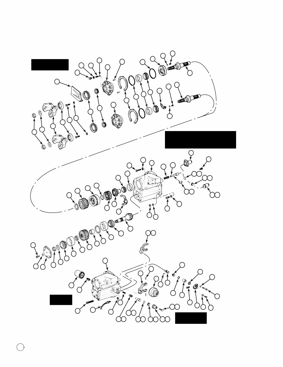
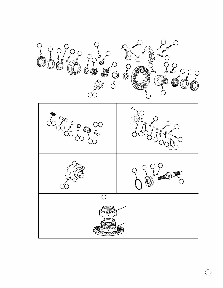
1 Exploded Views
Single-Reduction Forward Differential Carrier
Item Description
1 Nut — Input Yoke
1A Washer — Input Yoke
2 Input Yoke
3 Deflector
4 Capscrew — Cage-to-Carrier
5 Washer — Cage-to-Carrier
6 Oil Seal — Triple-Lip (Main) Seal
6A POSE™ Seal
7 Input Bearing Cage
8 Shims
9 O-Ring — Input Bearing Cage
10 Bearing Cup — Input Shaft
11 Bearing Cone — Input Shaft
12 Oil Baffle (Units Without Oil Pump)
13 Washer — Oil Baffle
14 Capscrew — Oil Baffle
15 Input Shaft
16 Thrust Washer — Helical Drive Gear
17 Helical Drive Gear
18 Inter-Axle Differential Case
Assembly
19 Snap Ring — Inter-Axle Differential
Case
20 Clutch Collar — Inter-Axle
Differential Case
21 Rear Side Gear
22 Shift Fork
23 Bearing Cone — Rear Side Gear
24 Bearing Cup — Rear Side Gear
25 Adjusting Screw — Shift Shaft
26 Jam Nut — Adjusting Screw
27 Spring — Shift Shaft
28 Shift Shaft and Piston
28A “E” Clip (Reverse Shift IAD Only)
29 Air Shift Chamber Assembly —
Bolt-On IAD
29A Air Shift Chamber Assembly —
Screw-In IAD
30 Capscrew — Air Shift Chamber
Assembly
31 Differential Carrier and Caps
32 Washer — Differential
Carrier-to-Axle Housing
33 Nut — Differential Carrier-to-Axle
Housing
34 Capscrew — Differential
Carrier-to-Axle Housing
35 Ring Gear and Drive Pinion
36 Inner Bearing Cone — Drive Pinion
37 Inner Bearing Cup — Drive Pinion
38 Shims
39 Inner Spacer
40 Helical Driven Gear
41 Outer Spacer
42 Outer Bearing Cup — Drive Pinion
43 Outer Bearing Cone — Drive Pinion
44 Washer — Drive Pinion
45 Nut — Drive Pinion
46 Cover — Drive Pinion
47 Washer — Drive Pinion Cover
48 Capscrew — Drive Pinion Cover
49 Bearing Adjusting Ring
50 Cup — Main Differential Bearing
51 Cone — Main Differential Bearing
52 Capscrew — Main Differential Case
Halves
53 Washer — Main Differential Case
Halves
54 Main Differential Case Assembly
55 Bolt — Ring Gear (145 and 160
Series)
56 Washer — Differential Bearing Cap
57 Capscrew — Differential Bearing
Cap
58 Roll Pin, Cotter Pin or Capscrew —
Differential Bearing Cap
59 Thrust Washer — Main Differential
Side Gear
60 Side Gear — Main Differential
61 Spider — Main Differential
62 Pinion Gear — Main Differential
63 Thrust Washer — Main Differential
63A NoSPIN
Main Differential
1
64 Washer — Ring Gear (145 and 160
Series)
65 Nut — Ring Gear (145 and 160
Series)
66 Sensor Switch — Main Differential
Lock
67 Locknut — Main Differential Lock
Sensor Switch (Early Design)
68 Spring — Main Differential Lock
68A Spring — Main Differential Lock —
Current Design
69 Lock Pin — Spring Retaining (Early
Design)
70 Shift Shaft — Main Differential Lock
Item Description
70A Shift Shaft — Main Differential Lock
— Current Design
71 Piston — Main Differential Lock
71A Piston — Main Differential Lock —
Current Design
72 O-Ring — Piston
72A O-Ring — Piston — Current Design
73 DCDL Cylinder — Shift Shaft
73A DCDL Cylinder — Shift Shaft —
Current Screw-In DCDL Design
74 Copper Gasket — Cover (160
Series)
75 Capscrew — Manual Engaging
75A Capscrew — Manual Engaging —
Current Design
76 Cover — Main Differential Lock
(Early Design)
77 Plug — Manual Engaging (Early
Design)
78 Washer — Manual Engaging
Capscrew
79 Capscrew — Cover (Early Design)
80 Washer — Cover (Early Design)
81 Shift Collar — Main Differential
Lock
82 Shift Fork — Main Differential Lock
82A Shift Fork — Main Differential Lock
— Current Design
83 Roll Pin — Shift Fork (Early Design)
84 Oil Filter Shield
85 Plug — Oil Pressure Relief Valve
86 Washer — Oil Pressure Relief Valve
87 Spring — Oil Pressure Relief Valve
88 Oil Pressure Relief Valve
89 Dowel — Input Cage to Oil Pump
(Early Design)
90 O-Ring — Oil Pump
91 Oil Pump
92 Washer — Oil Pump
93 Capscrew — Oil Pump
94 Oil Filter
95 Adapter — Oil Filter
96 Oil Screen and Plug Assembly
1
NoSPIN
is a registered trademark of Tractech, a
division of Dyneer Corp.
Item Description
1 Exploded Views
2 Meritor Maintenance Manual 5L (Revised 08-15)
Figure 1.1
L.H. SIDE
INPUT WITH
OIL PUMP PARTS
STANDARD DIFFERENTIAL
CARRIER WITHOUT DIFFERENTIAL
LOCK AND WITHOUT OIL PUMP
OIL PUMP
PARTS
DIFFERENTIAL
LOCK PARTS
93
92
15
91
90
15
14
12
13
11
10
9
8
7
6
6A
5
4
3
2
1A
1
84
85
86 87
88
7
89
30
29
28
27
31
26
25
24
23
22
21
20
19
18
17
16
48
47
46
45
44
43
42
41
40
39
38
37
36
35
94
95
96
66
67
68
31
33
32
34
32
82
83
81
69
70
71
72
73
74
75
76
78
77
79
80
75 A
73 A 71 A 72 A
70 A
68 A
28 A
29 A
82 A
71 A
72 A
1003392a
1 Exploded Views
3 Meritor Maintenance Manual 5L (Revised 08-15)
Figure 1.2
R.H. SIDE
PLAIN
CASE HALF
GEAR
CASE HALF
49
54 MAIN DIFFERENTIAL
CASE ASSEMBLY
49
50
51
65
64
54
59
60
63
62
61
60
59
31
58 58
57
56
55
53
52
49
50
51
54
35
EARLY DESIGN DCDL
68
71
74
80
79
77 78
76
75
73
72
70
69
67
OIL PUMP
90
91
92
93
15
CURRENT DCDL
68 A
70 A
72 A
71 A
73 A
75 A
NoSPIN
®
ASSEMBLY
63 A
63 A
1002701c
2 Introduction
4 Meritor Maintenance Manual 5L (Revised 08-15)
2 Introduction
Description
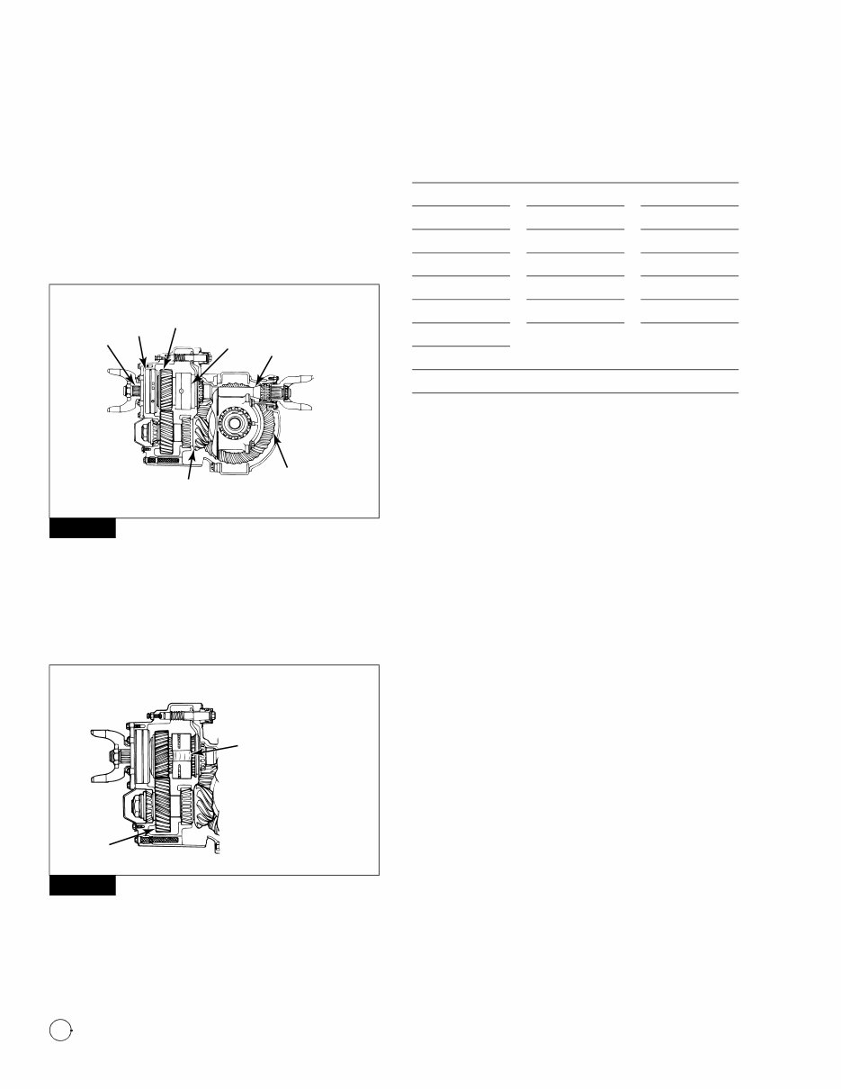
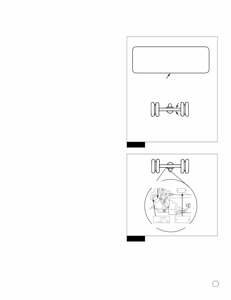
Forward Tandem Axle
The inter-axle differential is located behind the helical gear on the
input shaft. The forward side gear of the inter-axle differential is part
of the upper helical gear hub. The thru-shaft is splined to the rear
side gear of the inter-axle differential. Figure 2.1.
Figure 2.1
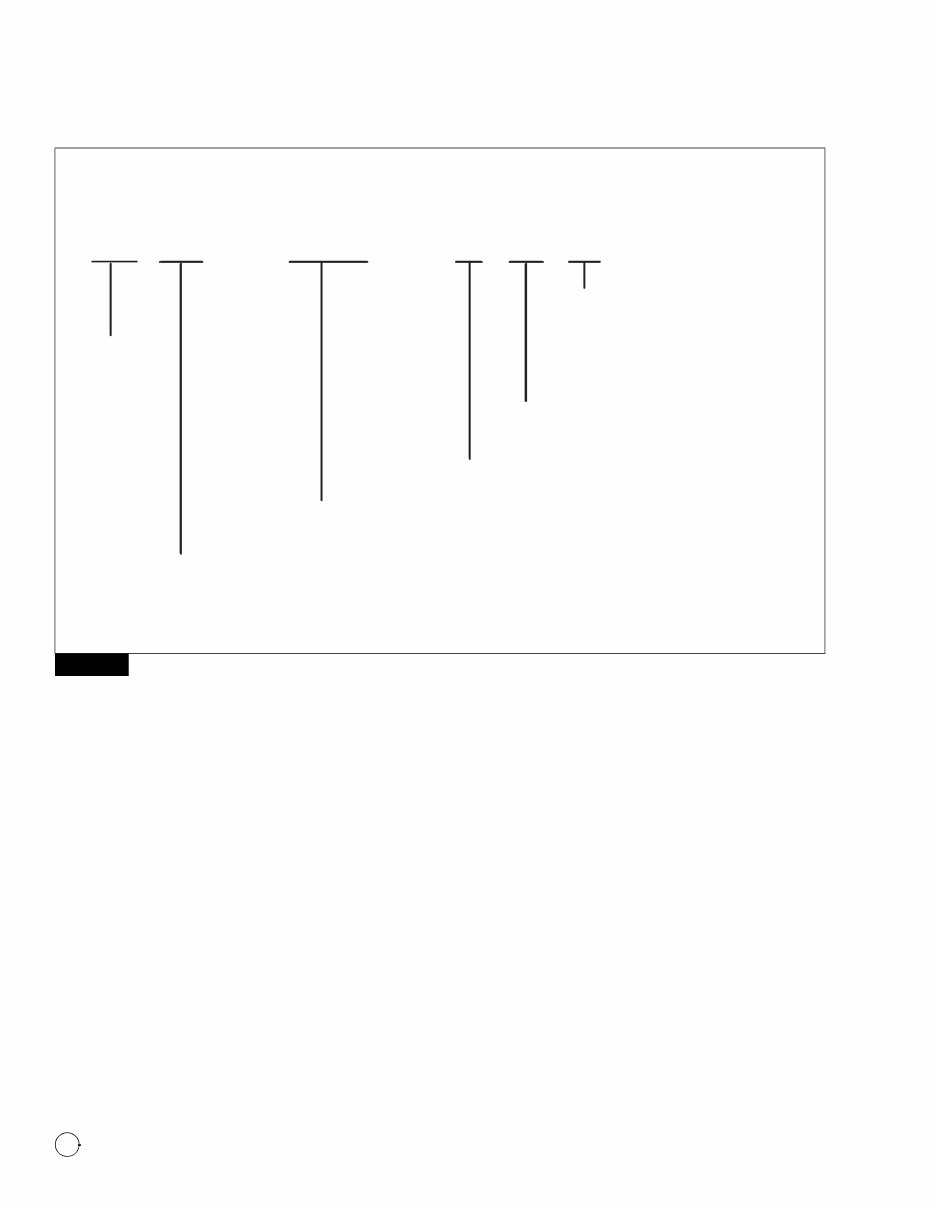
The Meritor 140, 145 and 160 forward tandem axles use a
single-reduction, thru-drive carrier. The drive gearing is a
two-helical gear train and a hypoid ring gear and pinion. Bevel gears
are used in the main differential and the inter-axle differential.
Figure 2.1 and Figure 2.2.
Figure 2.2
Axle Models Covered in This Manual
NOTE: For service procedures on rear carriers, refer to
Maintenance Manual 5, Single-Reduction Differential Carriers, for
models preceding RS-, RT- and RF-Series, and Maintenance Manual
5A, Single-Reduction Differential Carriers, for MX-, RS-, RT- and
RF-Series. To obtain these publications, refer to the Service Notes
page on the front inside cover of this manual.
Optional Pressurized Lubrication System
The forward axles can be equipped with an optional pressurized
lubrication system. This filtered system has an oil pump driven by
the input shaft. The pump circulates lubricant to the journals in the
forward and rear input shaft bearings and directly to the inter-axle
differential.
Optional Driver-Controlled Main Differential
Lock (DCDL)
Both the forward and rear axles can be equipped with an optional
driver-controlled main differential lock (DCDL). The differential lock
is operated by an air-actuated shift unit located on the forward axle
carrier.
When the differential lock is activated, the shift collar moves
along the splines of the axle shaft toward the differential case.
When the collar splines engage with the splines on the
differential case, the axle shaft and the differential assembly lock
together.
When the carrier operates with the DCDL in the locked position,
there is no differential action between the wheels.
When the carrier is operated in the unlocked position, there is
normal differential action between the wheels at all times.
Figure 2.1
Figure 2.2
OIL
PUMP
HELICAL
GEAR
INTER-AXLE
DIFFERENTIAL
OUTPUT
SHAFT
RING
GEAR DRIVE
PINION
INPUT
SHAFT
1002702c
Notch on inter-axle
differential case.
Notches are provided
for clearance in
assembly and
disassembly.
HELICAL
DRIVEN
GEAR 1002703c
RT-160 SERIES SHOWN
Tandem Models
RT-34-140 RT-40-145P RT-46-160
RT-34-144 RT-40-149 RT-46-160EH
RT-34-145 RT-40-160 RT-46-160P
RT-34-145P RT-40-169 RT-46-169
RT-40-140 RT-44-145 RT-50-160
MT-40-143 RT-44-145P RT-50-160P
RT-40-145 RT-46-16H EH RT-52-160P
RT-40-145A
Tridem Models
RZ-166 RZ-186 RZ-188
2 Introduction
5 Meritor Maintenance Manual 5L (Revised 08-15)
Inter-Axle Main Differential (IAD)
The Meritor inter-axle differential (IAD) is a driver-controlled,
air-actuated traction device. The IAD allows for speed differences
between the forward and rear axles in a tandem while also providing
equal pulling power from each axle of the tandem. By activating the
IAD switch located in the vehicle dash, improved traction is provided
for each axle.
The inter-axle differential is also known as a power divider or third
differential.
Stall-Testing Can Damage a Drive Axle
Stall-testing is a procedure used to troubleshoot transmissions,
evaluate vehicle performance, and test the service and park brakes.
During stall-testing, or any similar procedure, the drive axle input
receives multiplied torque, which can exceed the specified torque
rating. Excessive torque can damage a drive axle, which will affect
axle performance and component life. A drive axle damaged by
stall-testing will void Meritor’s warranty.
Call the Meritor OnTrac™ Customer Call Center at 866-668-7221 if
you have questions regarding stall-testing.
Use of Traction Chains
Meritor recommends that if you are using traction chains, you
should install chains on both tires on each side of all drive axles on
the vehicle.
Identification
Model Number
An identification tag is riveted on the axle housing or on the
differential carrier. Figure 2.3 and Figure 2.4. Use the model
number and the ratio number marked on the identification tag and
the number on the carrier to order replacement parts.
Figure 2.3
Figure 2.4
Refer to Figure 2.5 for an explanation of the model number.
Figure 2.3
Figure 2.4
Model No. . . . . . . . . . . . . . . . . . . .
Customer No. . . . . . . . . . . . . . . . .
Serial No. . . . . . . . . Plant . . . . . . . .
Ratio . . . . . . . . . . . .
IDENTIFICATION TAG
LOCATION OF THE IDENTIFICATION TAG, OR STAMP
NUMBER, FOR THE AXLES. LOCATION IS
DETERMINED FROM THE LEFT DRIVER SIDE
LOOKING TOWARD THE FRONT OF THE VEHICLE.
A — FRONT ENGINE DRIVE — RIGHT REAR, NEXT
TO COVER
B — REAR ENGINE DRIVE — LEFT OR RIGHT REAR,
NEXT TO DRIVE UNIT
A
B
1002704c
AXLE IDENTIFICATION TAG INFORMATION
CARRIER PART NO.
CUSTOMER NO.
SERIAL NO.
RATIO
Model No.
Customer No.
Serial No. Plant
Ratio Date
CARRIER PART NO.
CUSTOMER NO.
SERIAL NO.
RATIO
Model No.
Customer No.
Serial No. Plant
Ratio Date
AXLE
IDENTIFICATION TAG
CARRIER
IDENTIFICATION TAG
AXLE HOUSING
IDENTIFICATION TAG
4000625a
2 Introduction
6 Meritor Maintenance Manual 5L (Revised 08-15)
Figure 2.5
Figure 2.5
Axle Design V ariation: Indicates
axle design level or variation,
(e.g., RS-23-161 has a thicker
wall housing than RS-23-160).
For information, refer to the Bill
of Materials for that specific
axle model.
Carrier Type: Carrier size. Larger numbers
indicate a higher GCW rated Carrier; i.e.,
larger ring gear, etc.
Gearing Type:
1 = Single Speed
Nominal Axle Load Rating (GAWR): In thousands of pounds.
Individual forward and rear axles of a tandem set (D, N, P) are rated
as single axles. A tandem set (T) is rated as the combination of the
two axles.
Meritor
M T - - 1 4 X
Axle Type
D = Forward-Rear Axle of a Drive T andem with Inter-Axle Differential
N = Forward-Rear Axle of a Drive T andem without Inter-Axle Differential
P = Forward-Rear Axle of a Drive T andem with Inter-Axle Differential and Pump
T = T andem Drive Axle Set
40
CARRIER MODEL TAG NUMBER INFORMATION
1002705e
You're Reading a Preview
What's Included?
Fast Download Speeds
Online & Offline Access
Access PDF Contents & Bookmarks
Full Search Facility
Print one or all pages of your manual
$55.99
Viewed 12 Times Today


Secure transaction
What's Included?
Fast Download Speeds
Online & Offline Access
Access PDF Contents & Bookmarks
Full Search Facility
Print one or all pages of your manual
$55.99
This manual contains essential maintenance and service details for the Meritor forward tandem drive axles. It covers a range of models including the RT-140, -144, -145, -149, -160, -169, RZ-166, -186, and -188 Series models.


