

Engine SWAP GUIDE 1985-1992 GM TPI EFI system engine into a 1970 - 1981 Camaro - NOW
What's Included?
Fast Download Speeds
Online & Offline Access
Access PDF Contents & Bookmarks
Full Search Facility
Print one or all pages of your manual

This guide is designed specifically to swap a 1985-1992 GM TPI EFI
system/engine into a 1970-81 Camaro. Though, for the most part, it can be used
to swap in a TBI or LT1/LT4 engine/EFI system as well. All three engines install
like a conventional engine on the existing motor mounts and they have the same
transmission bell housing flange. The newest LS1/LS6 is a completely different
animal altogether requiring extensive chassis modifications to install and will not
be covered in this article.
The first thing you need to take stock of is your vehicle and the system
you will be installing. You need to also consider the emissions regulations in
your state and how you will meet those requirements. I’ll touch on the emissions
system briefly, telling how to hook it up. The emissions control systems are not
essential to engine operation (save for maybe PCV and canister purge), but
again, the emissions regulations will dictate their necessity from a legal
standpoint. In California, there is a rolling 30 year exemption meaning that
currently 1973 and older cars are exempt from smog. As such, I am not using
EGR, AIR injection, or any of the other late model smog devices. However, I did
retain my 1971 charcoal canister purge and PCV system.
This article will cover two possible scenarios. The first is that you have
bought an entire engine/transmission assembly or just the engine. You may or
may not have the factory wiring harness and computer, you may or may not all of
the sensors, injectors, and relays, or have bought new sensors to replace old or
damaged ones. In this scenario, you have already taken out your old engine and
or transmission and installed the new one in its place. You now need to
reconfigure the rest of the vehicle to run the new power plant. If you are
installing an LT1, this is your only scenario since the intake manifold cannot be
bolted on to an older small block without extensive modifications. However, if
you’re bent on doing something like that, visit the www.thirdgen.org site and do a
search. Several people have adapted LT1 manifolds to work the TPI. I will touch
briefly on the installation of a TH700R4 and how to adapt it in to a 2
nd
gen since
this is what I did. However, I will not discuss converting to a later model stick
shift since I have no experience in that area.
The second scenario is that you are putting the TPI/TBI system onto an
older engine. In this scenario, you have already removed the old carbureted
intake manifold and bolted on the new manifold. If you have TPI, only bolt on the
base plate at this point. It’ll be easier to wire and plumb the system with the
upper manifold and runners off (and the distributor out). Again, you now need to
reconfigure the rest of the vehicle to run the system. I’m kind of glossing over the
TPI base plate or TBI manifold installation part because putting on an intake
manifold or installing an engine is pretty generic and can be found in any repair
manual. The only caveat I have for this scenario is putting TPI or TBI on a
seriously modified engine- that is, one that has a camshaft over 214° intake
duration, cylinder heads with 180cc or more intake ports, full length headers and
free flowing exhaust systems, etc. Stock TPI/TBI engines were extremely
restricted as far as heads, cams, and exhaust systems go. Putting a bone stock
EFI system onto a modified engine like this will result in poor, disappointing

performance if you do not get the EPROM recalibrated for the new combination.
This will either require you to have a professional tuning shop do it, or you can
learn to do it yourself.
One thing to note before you get started is that I highly recommend using
the 1990-1992 system. So much so, that I’m going to focus solely on installing
this type of system. For reasons that will become apparent later in the guide,
1990-92 MAP systems are much more practical for EFI swaps than earlier 1985-
1989 MAF ones (see sensor section for definitions of MAP and MAF). If you
have a 1989 or earlier MAF system, you can upgrade it to the 1990-92
configuration very easily. I’ll cover that later on.
Another thing is that I would HIGHLY, HIGHLY suggest is buying a good
automotive scanner! I use an AutoXray. It’s a very nice tool. It will read trouble
codes, allow you to view real time operational data from the ECM (Electronic
Control Module, aka, computer) as well as record it for future reference. You can
also download this data into your PC and export it into Microsoft Excel for
graphing and further analysis. This tool is invaluable for diagnosing malfunctions
as well as for tuning, if you decide to get into that later. Actron also has a nice
scanner, but it cannot record data.
The main objective in an EFI swap is properly configuring the vehicle to
work with the system. This involves two areas- fuel and electrical systems. Both
need to be brought up to date. We’ll start with the fuel system.
Vehicle Fuel System Preparation
TPI/LT1 engines require a constant pressure of upwards of 40 psi to run
properly as well as a return line to the tank. TBI’s operate on a much lower
pressure of about 15 psi, but even they require a return line. In both cases, it
means you will need an electric fuel pump. This presents you with two choices-
either an in-tank pump or an external pump.
At first glance, the external pump may appear to be the easier method, but
it has several draw backs. The most obvious and complained about one is noise.
Since you will be mounting the pump to the chassis, the humming of the pump
will be transmitted through the frame and will be audible inside the vehicle. While
only a mild annoyance, it takes away from the “factory-ness” of the swap. The
second drawback is the heat generation. Cooling is mainly by convection
(whereas an in-tank pump is submerged in a cooling medium, the fuel). Since
there’ll be a lot of rubber (thermally insulating) padding to keep the pump
mechanically isolated from the frame (to reduce vibration noise transmission) the
heat conduction away from the pump is significantly reduced. Therefore,
overheating the pump is a possibility. The third problem is fuel starvation.
Unless internal baffling is added to the tank, low fuel levels combined with hard
braking/acceleration and/or hard cornering can uncover the fuel pickup allowing
the pump to suck air. Electric fuel pumps do not like to suck air since it reduces
the life of the pump significantly.
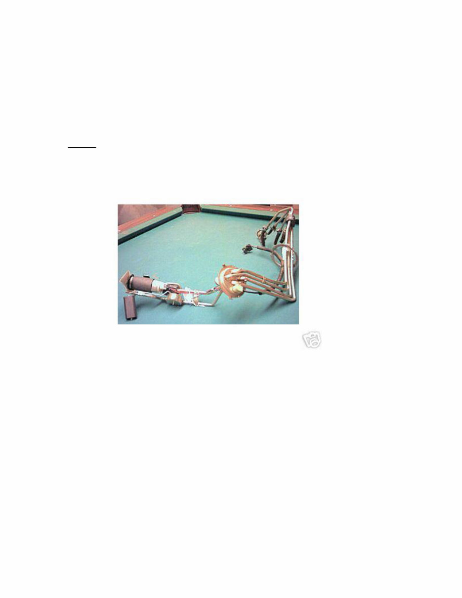
In my opinion, the best way to install an electric pump is to go in-tank. It’s
a lot easier than you may think and you eliminate all of the above problems. The
key to the installation is to find a V8 or V6 late-third generation fuel tank sender
like the one shown below.
NOTE: It was recently discovered that a third gen sender does not fit into late
second generation Camaro’s. It’s unknown the exact cut-off year. However, if
cannot verify if the opening for your sender is not the same as a 1970-73, then
this sender will not work with your fuel tank.
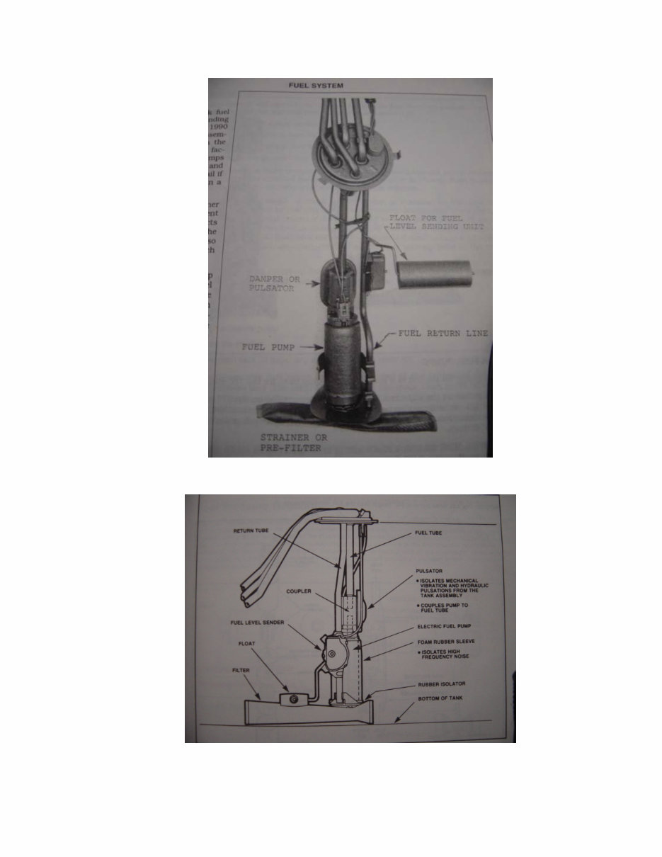
As you can see it has everything on it that you need and it’s a factory
setup! Now, the beauty of this is that it will fit into a second generation fuel tank
with minimal modifications. Namely:
1.) The depth of the fuel tanks between 2
nd
and 3
rd
gen tanks vary
with the model year. As such, minor bending of the lines
leading into the tank will probably be necessary. This can be
accomplished by hand (but be gentle and don’t kink the lines!).
Basically, measure the depth of your tank from the top flange of
the sending unit to the bottom of the tank and make sure that
the pump assembly is no more than 1/4” from the bottom.
2.) The fuel level electrical sender will operate the factory 2
nd
gen
fuel gauge perfectly (don’t you just love GM?). Both operate on
a 0-90 ohm potentiometer operated by a float arm. However
again, due to depth variations between tanks, you may need to
do some minor bending on the float arm such that it is calibrated
to the dimensions of your fuel tank. Just take the appropriate
measurements and you’re set.
3.) As you can see, this sending unit has a lot of fuel lines.
However on 2
nd
gens, you only need two of them. Find the
pressure line and the return line. The remaining two lines are
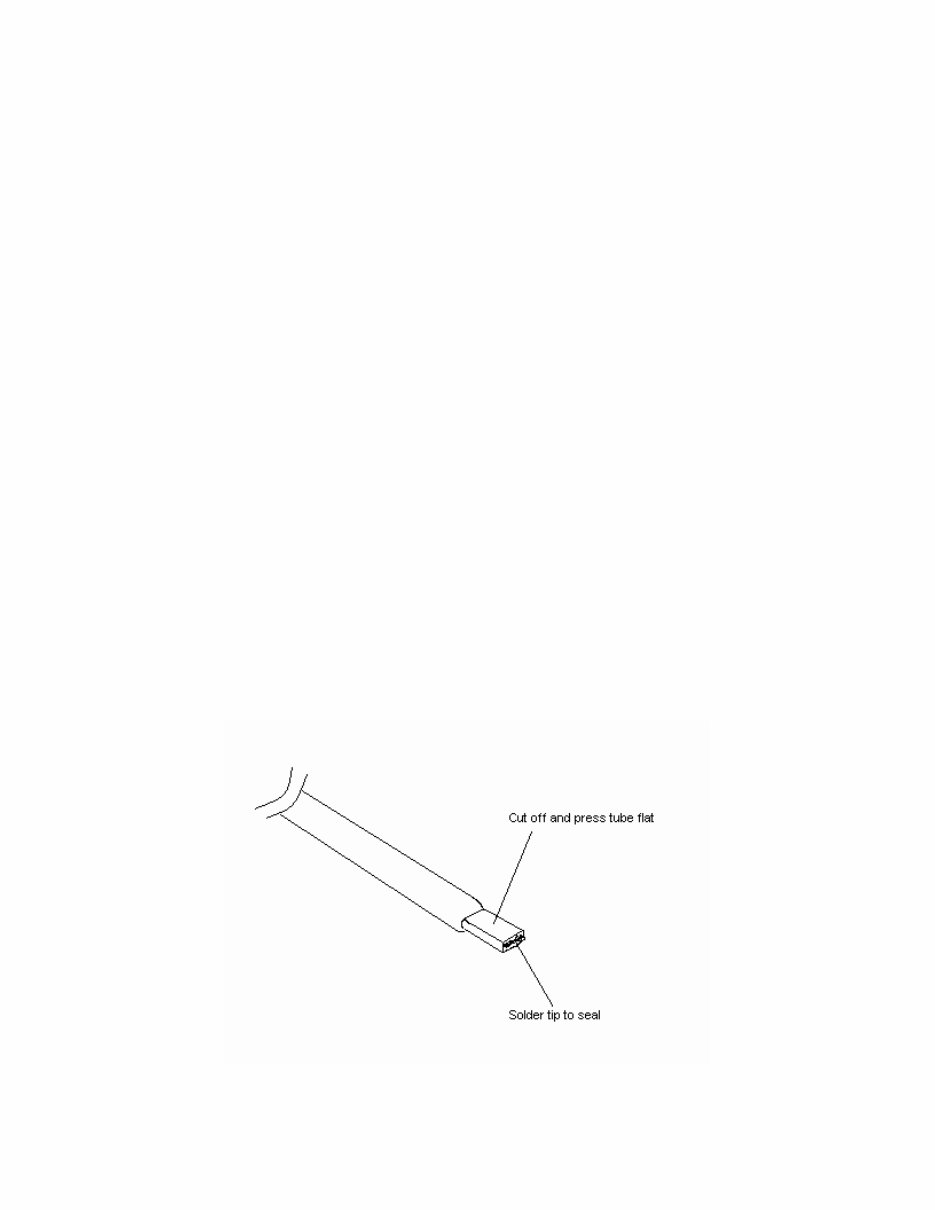
evaporative lines and can be deleted since the 2
nd
gen already
has evaporator lines integral on the tank. On mine, I simply cut
them a few inches from the root, pressed it flat about ½ inch
from the cut end, and soldered the tip shut with standard Sn63
solder to ensure a leak proof seal (see diagram below)
To plumb the lines to the tank you could use the stock 3/8 supply line that
runs the length of the car as the supply line for the EFI. However, you would
have to run high pressure rubber fuel injection hose from the supply line on the

sender to the line on the vehicle. You could also attempt to bend up some steel
line to run the length of the car for the return line as well or attempt to use the
vapor line as a return line. Some people have apparently done this successfully,
but I’d rather not do it in such a manner. Again, you’d have to have rubber hose
connections to mate up with the fuel sending unit. If you go this route, you NEED
to use high pressure fuel injection hose!!! There would also be the need to
plumb the steel lines into the fuel rail- calling for more adapters. I didn’t want to
deal with all of the rubber hose and adapters and such so I ditched the 1971
steel lines and went the Earl’s braided line route. Basically, I bought fittings that
allow you to hook up –AN braided steel hose to a steel fuel line. Today though,
Earl’s has tubing adapters that are specifically designed to allow you to hook up
braided steel line to the steel tubing. Simply call them up and as for fittings that
allow you to hook up -6 AN line to 3/8” steel tubing. They also have fittings that
utilize the factory fuel rail connections and allow you to plumb the braided hose
right to the fuel rail. This gives the benefit of running a one piece line from the
tank to the fuel rail (not counting the in-line high pressure fuel filter of course).
Not to mention that flexible braided steel hose is a lot easier to route than rigid
steel. One thing to keep in mind here, try to maintain as few connections as
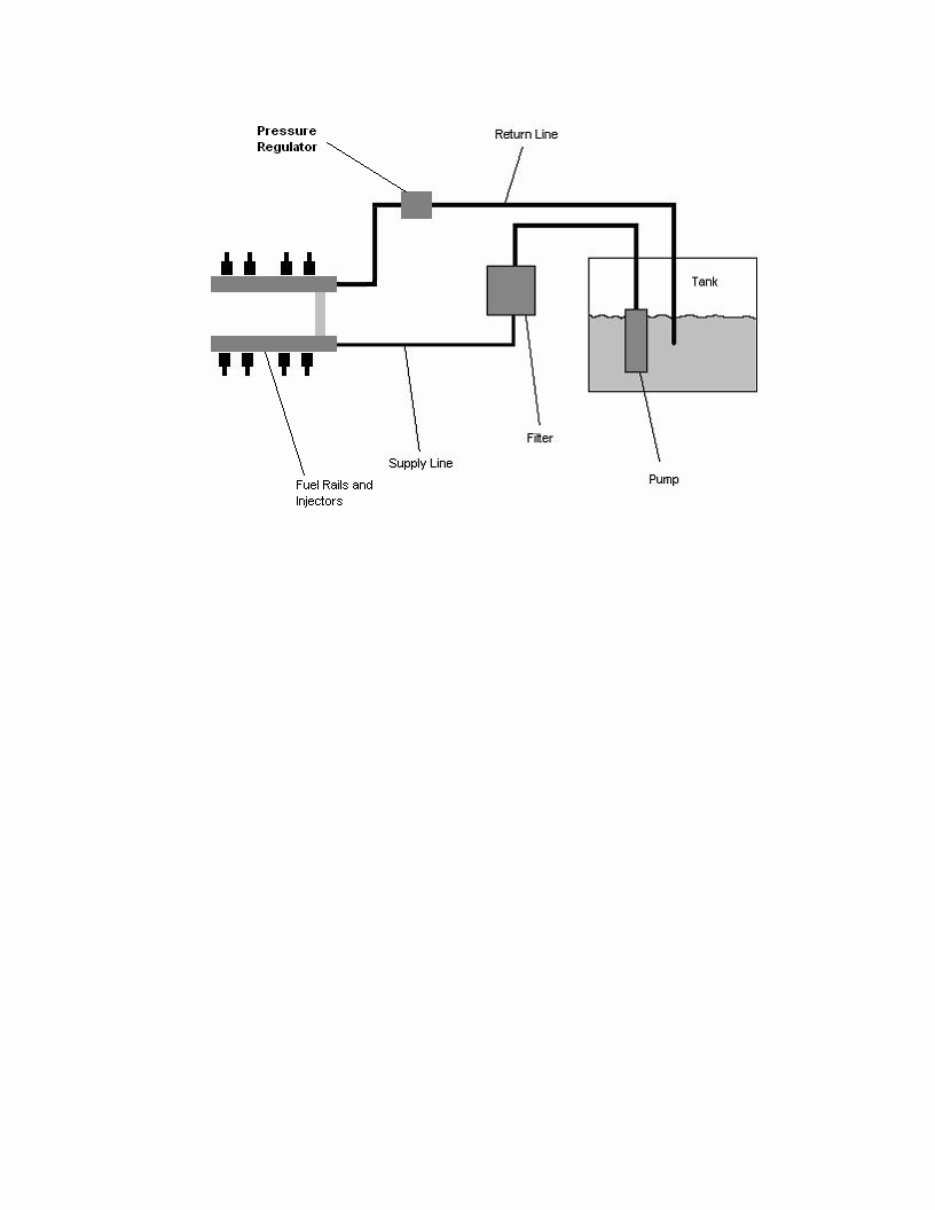
possible since each additional connection is a potential source for leaks! Below
is a EFI fuel system block diagram:
NOTE : I recently discovered that gasoline can permeate through braided rubber
fuel line and result in a constant fuel odor, particularly when the vehicle is parked
inside a garage. This is most likely due to various fuel additives in certain parts
of the United States. One possible remedy, aside from hard steel lines, is to run
braided teflon lines. Teflon lines are available from a variety of sources. While I
did this option on my Camaro (which ridded me of the fuel smell), Aeroquip has
posted a disclaimer about running any type of braided line on EFI engines.
http://www.aeroquip.com/media/performance/A-SPPE-MC001-E-p54.pdf
The fuel recirculation can oxidize the fuel which can allow to attack and
deteriorate the hose. Therefore, I am not recommending running braided
hose , but merely presenting the option as many people are already doing this
rather than forming hard steel lines.
Lastly, the fuel starvation problem needs to be addressed. 2
nd
gen fuel
tanks were obviously not designed for EFI. Electric pumps meet an early demise
if starved for fuel too many times which is why late model fuel tanks have
complex baffle systems inside. This prevents starvation during high-g
maneuvers. On my tank, I did the best I could to mimic the baffle philosophy by
welding in a tray on the bottom of the tank. Basically, a gas tank shop cut out a
section of the tank floor, welded a tray to it and then welded the floor back in.
The tray looks like just that, a tray. It’s rectangular and a couple of inches tall. It
has four holes (one at each corner near the bottom of the tray walls) to allow fuel
to slowly enter in to the tray, but keep it from getting away from the pump. I
forget the exact dimensions (since I did this about 7 or 8 years ago) but I would
suggest a tray about one foot long by about one foot wide by about two to three
inches tall. Here’s a generic view of what I’m talking about. The pump doesn’t
necessarily have to sit in the tank like this though. In fact, with the third gen
sending unit, the pump will be pointing toward the back of the tank.

In any case, the then hangs down and sits in the of the tray. This is not a
sump. From the outside, the tank looks stock. This baffle tray is completely
inside the tank. What I would suggest is to fit your fuel tank sender in and then
take the tank and sender to a shop and describe what you’re doing. If they are at
all able to do some custom work they should be able to do this. That’s basically
how I did it.
For the pump itself, I’m running a Holley high-performance in-tank pump.
It feeds my modified ZZ4 (~400hp) just fine.
Another option for an EFI fuel tank is to contact Rock Valley
(www.rockvalleyantiqueautoparts.com/history.htm ). They can build a custom
stainless steel tank for your 2
nd
gen Camaro. The tank already has baffles in it
and is setup for EFI. It’s pretty pricey at about $1000, but it comes ready for use.
The above applies to all TPI/TBI/LT1 engines. Like I said, the only thing
that will vary is the type of pump used- TPI/LT1 vs. TBI. Obviously, the higher
the horsepower and displacement of the engine, the higher the pump output
you’ll need.
While I’m on the subject of the fuel systems, let’s talk injectors and fuel
pressure regulators. Since I don’t recommend putting TBI on a high performance
engine, I’m going to stick with the TPIs and LT1s. They use the same injectors.
305 TPIs came stock with 19 lb/hr injectors, on 350 TPIs that was increased to
22 lb/hr. When the LT1s came out, they received 24 lb/hr units. Rule of thumb, if
you’re aiming for over 350 hp (which is pretty easy these days), upgrade to 24
lb/hr injectors. Additionally, don’t try to run 305 injectors on a 350 (especially if
it’s a modified 350). They have insufficient capacity to feed that much
displacement. The cheapest place I’ve found that sells injectors is Summit
Racing. Matter of fact, I’m running Ford Motorsport 24 lb/hr injectors! I know…
“HERESY HERESY TRAITOR!!” Hey what can I say, they use the same
injectors that GM does, but they charge about half as much. At Summit, they
cost about $220. For the regulator, you can run the factory regulator, but you’ll
stuck with the factory fuel pressure. While not really a bad thing, but if you want

to up the pressure a little you’ll have to install an adjustable fuel pressure
regulator. There are a ton of them out there- Crane, TPI Specialties, Granatelli,
Holley, etc. They’re all pretty much the same, so whatever strikes your fancy.
Injector operation varies between TPIs and LT1s. All TPIs were batch fire
systems. That is, the computer alternately fires all four driver side injectors then
all four passenger side injectors. 1993 LT1s had the same style injector
operation. However in 1994, GM changed to sequential injection where each
injector is timed to fire per the engine firing order. Sequential injection has a little
bit of an advantage at low RPMs (usually showing up in idle quality). But in the
mid-range and high RPMs, the speed of the engine is high enough that the timing
of the injectors becomes less important.
Lastly, remember that you need a high pressure EFI fuel filter!!
And, it’s directional at that. Make sure you install it with the arrow (on the filter
housing) pointing in the right direction!!!
Well, this pretty much takes care of the fuel system.
Vehicle Electrical System Preparation
The electrical system of an EFI system is not as complicated as you might
think. Nonetheless, the vehicle must first be prepared to handle the demands of
a late model engine management system. Like I said previously, they call the
system “stand-alone” because of the system’s minimal interfacing with the rest of
the vehicle’s electrical system. On the EFI harness, the only places where the
system connects electrically to the vehicle are power and ground. There is one
hook up to the battery, one hookup to +12V switched power source, and a few
ground locations (typically engine and chassis). As such, the system basically
stands alone. I will take you through the electrical preparation, but also guiding
you through the engine schematic explaining the sensor operation. Again, this is
something most TPI swapping guides do not do. If you are unfamiliar with wiring
schematics, this will help you familiarize yourself with them. It’s important that
you do so that when problems arise with the installation (and they usually do the
first time through), you will be able to more successfully diagnose the situation.
First of all, you need to make sure that your vehicle’s electrical system is
up to the task of powering an EFI system! Remember, you’re going to be adding
eight fuel injectors, a computer, a fuel pump, electric fans (likely), sensors,
relays, etc. This is going to place a much heavier demand than your original
electrical system was designed to handle. First, examine your power wire going
from the battery to the alternator- make sure it is in good condition. In fact, I
would strongly suggest upgrading it to a heavier gauge wire since you’re going to
have to have a high output alternator. Also, ensure you have excellent (not just
good) grounds going from the battery to the engine, engine to chassis, and even
battery to chassis. It sounds redundant, but trust me, EFI systems do not like
electrical ground loops. All of your chassis grounds from the EFI harness must
You're Reading a Preview
What's Included?
Fast Download Speeds
Online & Offline Access
Access PDF Contents & Bookmarks
Full Search Facility
Print one or all pages of your manual
$31.99
Viewed 94 Times Today


Secure transaction
What's Included?
Fast Download Speeds
Online & Offline Access
Access PDF Contents & Bookmarks
Full Search Facility
Print one or all pages of your manual
$31.99
This manual is specifically designed for swapping a 1985-1992 GM TPI EFI system/engine into a 1970-1981 Camaro. It can also be used for swapping in a TBI or LT1/LT4 engine/EFI system. All three engines install like a conventional engine on the existing motor mounts and they have the same transmission bell housing flange.
Please note that the newest LS1/LS6 requires extensive chassis modifications for installation and is not covered in this manual.


