

1966-1983 Chrysler Marine 3.5-140HP Engines Service & Repair Manual
What's Included?
Fast Download Speeds
Online & Offline Access
Access PDF Contents & Bookmarks
Full Search Facility
Print one or all pages of your manual

TABLE OF CONTENTS
1 SAFETY
INTRODUCTION 1-1
CLEANING, WAXING, & POLISHING 1-1
CONTROLLI NG CORROSION
PROPELLERS
Diameter & Pitch
Proper Selection
Cavitation
Vibration
Shock Absorbers
Propeller Rake
Progressive Pitch
Cupping
FUEL SYSTEM
Taking on Fuel
Static Electricity
Fuel Tank Grounding
LOADING
HORSEPOWER
FLOTATION
EMERGENCY EQUIPMENT
COMPASS
ANCHORS
MISCELLANEOUS EQUIPMENT
BOATING ACCIDENT REPORTS
NAVIGATION
2 N NING
INTRODUCTION
TUNE- UP SEQUENCE
COMPRESSION CHECK
SPARK PLUG INSPECTION
IGNITION SYSTEM
TIMING & SYNCHRONIZING
BATTERY CHECK
FUEL & FUEL TANKS
GENERAL CARBURETOR INFO.
SPECIFIC CARBURETOR INFO.
Walbro LMB, Carburetor "A"
Tillotson MT, Carburetor "B"
Tillotson MD, Carburetor "C"
Tillotson CO, TC, & WB --
Carburetor "D"
Walbro WE, Carburetor "E"
Amal, Carburetor "F"
TACHOMETER LESSON
FUEL SYSTEM
Fuel Pumps
CRANKING MOTOR
INTERNAL WIRING HARNESS
WATER PUMP CHECK
PROPELLER
LOWER UNIT
BOAT TESTING
3 MAINTENANCE
INTRODUCTION 3-1
OUTBOARD SERIAL NUMBERS 3-2
LUBRICATION - - COMPLETE UNIT 3-2
PRE-SEASON PREPARATION
SEALANTS, ADHESIVES, LUBRI-
CANTS, HYDRAULIC FLUID,
AND STABILIZERS
BELOW WATERLINE SERVICE
INSIDE THE BOAT
SUBMERGED ENGINE SERVICE
LOWER UNIT
PROPELLER SERVICE
WINTER STORAGE
Battery Storage
4 FUEL
INTRODUCTION
GENERAL CARBURETOR INFO.
CARBURETOR MODELS
FUEL SYSTEM
Leaded Gasoline & Gasohol
Removing Fuel From System
TROUBLESHOOTING
Fuel Problems
"Sour" Fuel
(c) PDF Manual Publisher
4 FUEL (CONTINUED)
TROUBLESHOOTING (CONT.)
Fuel Pump Test
Fuel Line Test
Rough Engine Idle
Excessive Fuel Consumption
Engine Surge
SERVICE CARBURETOR "A" --
WALBRO LMB
Removal & Disassembling
Cleaning & Inspecting
Assembling & Installation
SERVICE CARBURETOR "B" --
TILLOTSON MT
Removal & Disassembling
Cleaning & Inspecting
Assembling & Installation
SERVICE CARBURETOR "C" --
TILLOTSON MD
Removal & Disassembling
Cleaning & Inspecting
Assembling & Installation
SERVICE CARBURETOR "D" --
TILLOTSON CO, TC, & WB
Removal & Disassembling
Cleaning & Inspecting
Assembling & Installation
SERVICE CARBURETOR "El1 - -
WALBRO WE
Removal & Disassembling
Cleaning & Inspecting
Assembling & Installation
SERVICE CARBURETOR "F" - -
THE AMAL
TACHOMETERS & CONNECTIONS 4-56
FUEL PUMP 4-57
Description & Operation 4-57
Pressure Check 4-58
Removal & Disassembling 4-59
Cleaning & Inspecting 4-62
Assembling & Installation 4-62
5 IGNITION
INTRODUCTION 5- 1
SPARK PLUG EVALUATION 5-2
POLARITY CHECK 5-5
WIRING HARNESS 5-6
TROUBLESHOOTING BASIC COMPO-
NENTS 5-6
TESTING BASIC COMPONENTS 5-9
FLYWHEEL REMOVAL & INSTALLA-
TION 5-14
Model 3.5hp thru 30hp 5-14
Model 35hp & Larger 5-16
Cleaning & Inspecting 5-1 7
Flywheel Magnets
Model 3.5hp thru 30hp
Model 35hp & Larger
TYPE I IGNITION SYSTEM --
FLYWHEEL MAGNETO -
BATTERY TYPE --
MAGNAPOWER I
Component Function
Operation Description
Testing Type I
Servicing Type I
Cleaning & Inspecting
Installation
TYPE I1 IGNITION SYSTEM --
MAGNAPOWER I1
Description & Operation
Testing Type I1
Servicing Type I1
Cleaning & Inspecting
Assembling & Installation
TYPE I11 IGNITION SYSTEM --
CD (CAPACITOR DISCHARGE) -
PRESTOLITE MAGNAPOWER I11
Description & Opera tion
Testing Type I11
Servicing Type I11
Cleaning & Inspecting
Assembling & Installation
TYPE IV IGNITION SYSTEM
UNITS WITH DISTRIBUTOR
Description & Operation
Testing Type IV
Servicing Type IV
Cleaning & Inspecting
Assembling & Installation
6 TIMING AND SYNCHRONIZING
INTRODUCTION & PREPARATION
TACHOMETERS & CONNECTIONS
IGNITION TIMING
CARBURETOR SYNCHRONIZING -
GENERAL ADJUSTMENTS
Throttle Pickup Adjustment
Idle Mixture Adjustment
Idle Speed Adjustment
Neutral Warmup
Electric Choke Adjustment
SYNCHRONIZE CARBURETOR "A"
Static Adjustments 6-7
Dynamic Adjustments 6-8
SYNCHRONIZE CARBURETOR "B" 6- 9
Static Adjustments 6-10
Dynamic Adjustments 6-11
SYNCHRONIZE CARBURETOR "C" 6-12
Static Adjustments 6-13
Dynamic Adjustments 6-13
(c) PDF Manual Publisher
SYNCHRONIZE CARBURETOR "D" 6- 14
Static Adjustments 6 - 15
Dynamic Adjustments 6- 16
SYNCHRONIZE CARBURETOR "D"
OR CARBURETOR "E" 6- 18
Static Adjustments 6-1 9
Dynamic Adjustments 6- 24
IGNITION TIMING - - ALL MODELS
35HP AND LARGER
General Information 6- 26
Model 35hp -- 1976 - 79
and 1983- 84 6- 27
IGNITION TIMING AT WOT - - MODELS
WITH FLYWHEEL MARKS 6- 27
Establishing TDC & BTDC Marks 6 - 28
IGNITION TIMING - - 35HP THRU
55HP, SPECIFIC YEARS 6- 31
IGNITION TIMING -- 55HP THRU
65HP & ALL 4 - CYLINDER
W/O DISTRIBUTOR 6- 34
IGNITION TIMING --
WITH DISTRIBUTOR 6- 35
SYNCHRONIZE CARBURETOR "F" 6- 38
7 POWERHEAD
INTRODUCTION AND CHAPTER
ORGANIZATION
TWO- CYCLE POWERHEAD
Description & Operation
Physical Operation
Timing -- 2 - Stroke Unit
Cooling Lecture
Cylinder Drain System
PREPARATION FOR SERVICE
Removal -- Misc. Components
Intake Manifold & Reed Block
POWERHEAD REMOVAL
AND DISASSEMBLING
Crankshaft & Rod Removal
Main Bearings
Piston Removal
Crankshaft Disassembling
CLEANING & INSPECTING
Thermostat Service
Temperature Sender
Crankshaft Service
Rod Service
Piston Service
Ring End Gap
Cylinder Block
Hone Cylinder Walls
Block & Head Warpage
Crankcase Cover
POWERHEAD ASSEMBLING
AND INSTALLATION
Assembling Pistons & Rods
Installing Pistons & Rods
Crankcase Cover
Exhaust Cover
Upper Oil Seal Housing
Power head Installation
Closing Tasks
Sealing Service Words
Thermoswitch
Supporting Components
8 ELECTRICAL
INTRODUCTION 8- 1
BATTERIES 8- 1
Marine Batteries 8- 1
Construction 8- 2
Ratings 8 - 2
Service 8- 3
Jumper Cables 8- 6
Storage 8- 6
TACHOMETER 8- 7
GENERAL ELECTRICAL
INFOR MATION 8- 7
CHARGING CIRCUIT SERVICE 8- 8
Rectif ier/Regulator 8 - 8
Stator Service 8- 10
CRANKING MOTOR CIRCUIT 8- 11
Description 8- 1 1
Troubleshooting 8 - 13
Installation 8- 15
CRANKING MOTOR SERVICE 8- 16
Description 8- 16
Removal & Disassembling 8- 16
Cleaning & Inspecting 8 - 18
Testing Components 8- 20
Assembling 8- 23
TESTING OTHER COMPONENTS 8- 26
TrimITilt Switch 8- 26
Trim/Til t Motor 8- 27
Ignition Switch 8- 27
"Kill" Switch 8- 28
Shift Interlock Switch 8- 28
Overheat Warning Horn 8 - 29
Circuit Breaker 8- 29
AUTO ELECTRIC SYSTEM 8- 30
Description 8- 30
Removal & Disassembling 8- 30
Cleaning & Inspecting 8-31
Assembling 3c Installation 8- 33
INTRODUCTION AND CHAPTER
ORGANIZATION 9- 1
SYSTEM OPERATION 9- 2
Electric Motor 9-2
Hydraulic Pump 9- 2
(c) PDF Manual Publisher
9 TRIM/TILT (CONTINUED)
PURGING AIR FROM SYSTEM
TROUBLESHOOTING
Hydraulic Test
Electrical Test
SERVICE PUMP & MOTOR
Removal
Disassembling
Testing Motor
Assembling
Installation
SERVICE CYLINDERS
Preliminary Tasks
TILT CYLINDER
Disassembling
Cleaning & Inspecting
Assembling
TRIM CYLINDER
Disassembling
Cleaning & Inspecting
Assembling
Installation
SYSTEM -- ONE TRIMITILT CYL.
TWO DESIGNS INCLUDED
Removal
Disassembling
Cleaning & Inspecting
Assembling & Installation
TRIMITILT SENDING UNIT
10 LOWER UNIT
CHAPTER ORGANIZATION
TROUBLESHOOTING
PROPELLER SERVICE
ONE- & TWO- CYLINDER UNITS
PROPELLER SERVICE
3- & 4 - CYLINDER UNITS
FILLIDRAIN ALL LOWER UNITS
SERVICE L.U. TYPE "A"
CONSTANT MESH -- NO SHIFT
Removal
Disassembling
Cleaning & Inspecting
Assembling
Installat ion
SERVICE L.lJ. TYPE "B"
ONE PIECE -- CAM SHIFT
F- N OR F- N- R
Removal
Disassembling
Cleaning & Inspecting
Assembling
Installat ion
SERVICE L.U. TYPE "C"
ONE PIECE - COUPLER SHIFT
F- N- R 10 - 39
Removal 10 - 39
Disassembling 10- 41
Cleaning & Inspecting 10- 47
Assembling 10- 51
Backlash 10- 53
Prop. Shaft End " Play" 10-58
Installation 10- 62
SERVICE L.U. TYPE "Dlt
TWO- PIECE -- CAM OR COUPLER
SHIFT - - F- N- R 10- 64
Removal 10- 64
Disassembling 10- 66
Cleaning & Inspecting 10 - 73
Assembling 10- 77
Prop. Shaft End Play 10- 85
Installation 10- 87
11 HAND REWIND STARTER
INTRODUCTION AND
CHAPTER COVERAGE 11- 1
SERVICE TYPE "A" --
MOUNTED ATOP FLYWHEEL 11- 2
Removal & Disassembling 11- 2
Cleaning & Inspecting 11- 4
Assembling & Installation 11-5
SERVICE TYPE "B"--
MOUNTED ATOP FLYWHEEL 11- 9
Removal & Disassembling 11- 10
Cleaning S( Inspecting 11 - 12
Assembling & Installation 11- 12
Check Interlock System 11- 16
SERVICE TYPE "C" --
SPOOL MOUNTED VERTICALLY
THREE MODELS INCLIJDED 11- 17
Replace Frayed or
Broken Rope 11- 17
Cleaning & Inspecting 11- 22
Installation 11 - 23
Replace Broken Spring 1 1- 26
Cleaning & Inspecting 1 1- 27
Installation 1 1- 28
Adjust Interlock System 11- 30
12 REMOTE CONTROL
INTRODUCTION 12- 1
OPERATION 12- 1
SERVICING 12- 1
Removal & Disassembling 12- 2
Cleaning & Inspecting 12- 5
Assembling & Installation 12-6
(c) PDF Manual Publisher

APPENDIX
METRIC CONVERSION TABLE
DRILL SIZE CONVERSION CHART
TORQUE SPECIFICATIONS
ENGINE SPECIFICATION AND
TUNE-UP ADJUSTMENTS
1962 thru 1966
1967 thru 1969
1970 and 1971
1972 and 1973
1974 and 1975
1976 and 1977
1978 and 1979
1980 and 1981
1982 and 1983
1984
POWERHEAD SPECIFICATIONS A-24
CYLINDER COMPRESSION A-26
LOWER UNIT OIL CAPACITY A-27
CARBURETOR JET SIZE/
ELEVATION CHART A-28
WIRING DIAGRAMS WITH
COLOR CODE
By Horsepower
& Ignition System A-29 thru A-53
(c) PDF Manual Publisher

SAFETY
1-1 INTRODUCTION
In order to protect the investment for
the boat and outboard, they must be cared
for properly while being used and when out
of the water. Always store the boat with
the bow higher than the stern and be sure to
remove the transom drain plug and the inner
hull drain plugs. If any type of cover is used
to protect the boat, be sure to allow for
some movement of air through the hull.
Proper ventilation will assure eiaporation of
any condensation that may form due to
changes in temperature and humidity.
1-2 CLEANING, WAXING, AND POLISHING
Any boat should be washed with clear
water after each use to remove surface dirt
and any salt deposits from use in salt water.
Regular rinsing will extend the time be -
tween waxing and polishing. It will also give
you " pride of ownership " , by having a sharp
looking piece of equipment. Elbow grease, a
mild detergent, and a brush will be required
to remove stubborn dirt, oil, and other un -
sightly deposits.
Stay away from harsh abrasives or strong
chemical cleaners. A white buffing com -
pound can be used to restore the original
gloss to a scratched, dull, or faded area.
The finish of your boat should be thoroughly
cleaned, buffed, and polished at least once
each season. Take care when buffing or
polishing with a marine cleaner not to over -
heat the surface you are working, because
you will burn it.
The first form was merely rot in the wood
and then it was rust, followed by other
forms of destructive corrosion in the more
modern materials. One defense against cor -
rosion is to use similar metals throughout
the boat. Even though this is difficult to do
in designing a new boat, particularly the
undersides, similar metals should be used
whenever and wherever possible.
A second defense against corrosion is to
insulate dissimilar metals. This can be done
1-3 CONTROLLING CORROSION A well kept unit, cleaned, serviced, tuned, and ready
to leave the service facility. Proper care reflects the
Since man first started out on the water, owner's "pride of ownership" and will be rewarded with
corrosion on his craft has been his enemy.
p zrf orm ance.
(c) PDF Manual Publisher
1 - 2 SAFETY
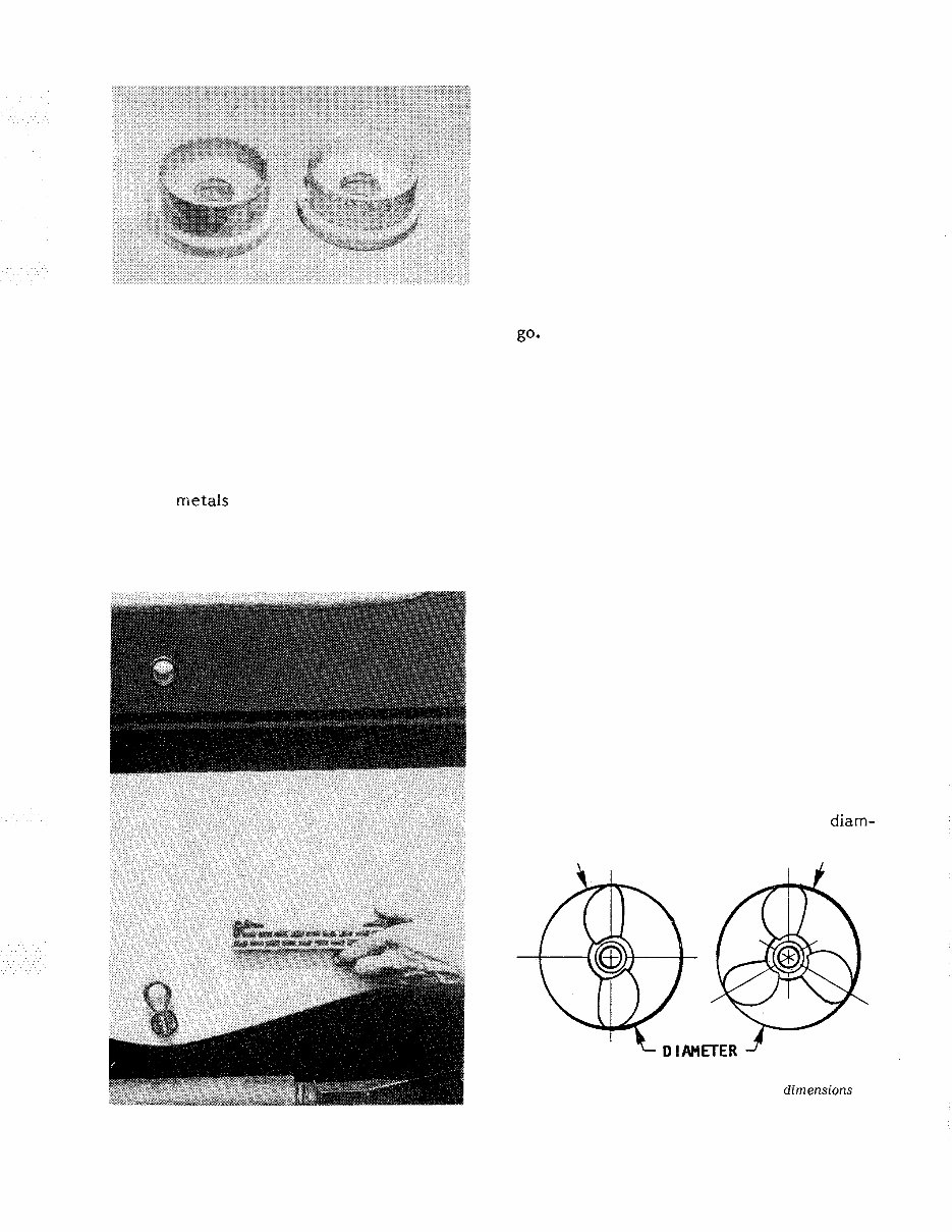
A new anode, left, compared with a slightly used
one, right. This type anode is attached to the bearing
carrier on larger hp units.
by using an exterior coating of Sea Skin or
by insulating them with plastic or rubber
gaskets.
Using Zinc
The proper amount of zinc attached to a
boat is extremely important. The use of too
much zinc can cause wood burning by plac -
ing the metals close together and they be -
come "hot". On the other hand, using too
small a zinc plate will cause more rapid
deterioration of the metal you are trying to
Mounting a large zinc on the transom to protect
more valuable parts.
protect. If in doubt, consider the fact that
it is far better to replace the zincs than to
replace planking or other expensive metal
parts from having an excess of zinc.
When installing zinc plates, there are
two routes available. One is to install many
different zincs on all metal parts and thus
run the risk of wood burning. Another
route, is to use one large zinc on the tran -
som of the boat and then connect this zinc
to every underwater metal part through
internal bonding. Of the two choices, the
one zinc on the transom is the better way to
go*
1- 4 PROPELLERS
As you know, the propeller is actually
what moves the boat through the water.
This is how it is done. The propeller oper -
ates in water in much the same manner as a
wood screw does in wood. The propeller
" bites " into the water as it rotates. Water
passes between the blades and out to the
rear in the shape of a cone. The propeller
" biting" through the water in much the same
manner as a wood auger is what propels the
boat.
All units covered in this manual are
equipped, from the factory, with a through
the propeller exhaust. With these units,
exhaust gas is forced out through the pro -
peller.
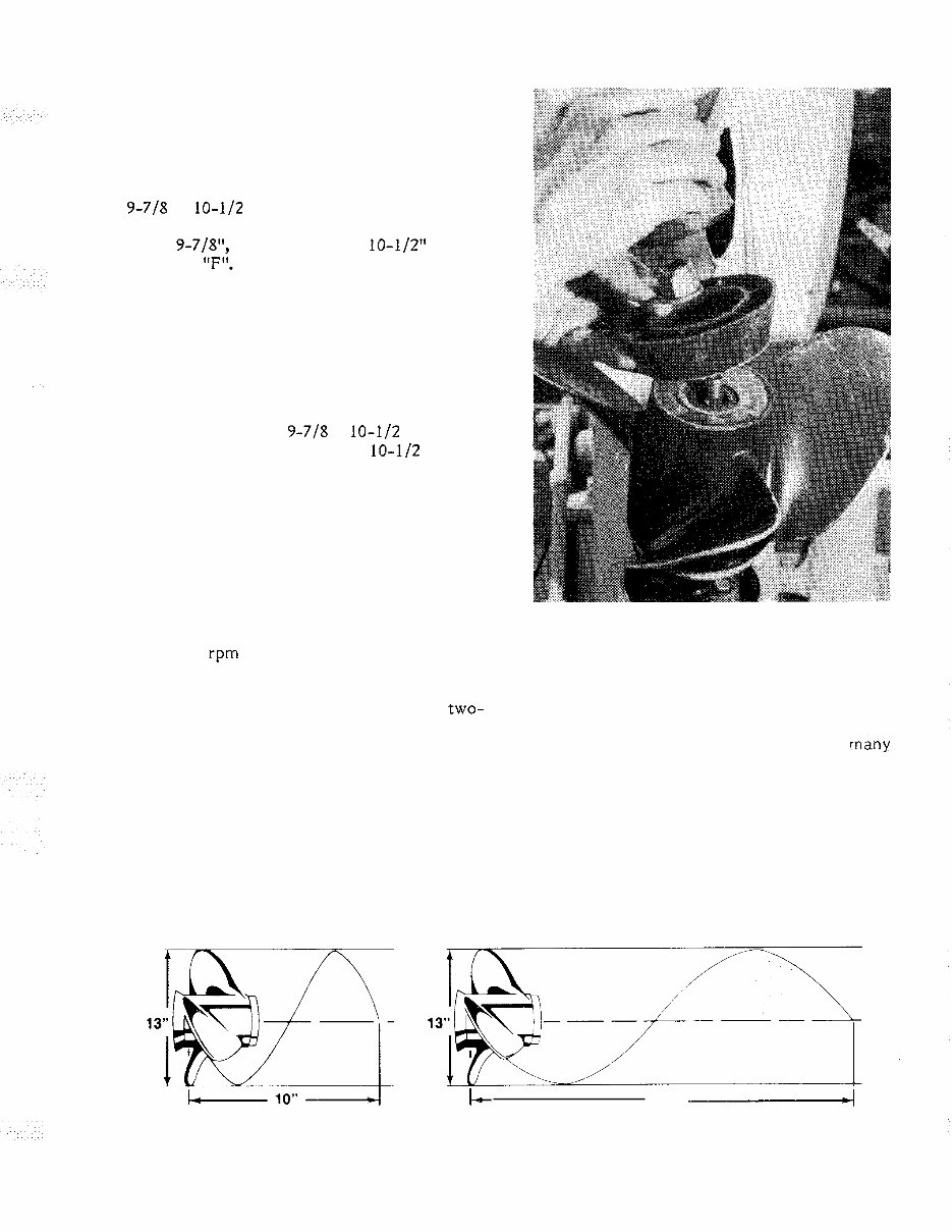
Diameter and Pitch
Only two dimensions of the propeller are
of real interest to the boat owner: the
diameter and the pitch. These two dimen -
sions are stamped on the propeller hub and
always appear in the same order: the diam-
Diameter and pitch are the two basic dimensions of
a propeller. The diameter is measured across the
circumference of a circle scribed by the propeller
blades, as shown.
(c) PDF Manual Publisher
PROPELLERS 1 - 3
eter first and then the pitch. Propellers
furnished with the outboard by the manufac -
turer for the units covered in this manual
have a letter designation following the pitch
size. This letter indicates the propeller
type. For instance, the numbers and letter
9-718 x 10-112 - F stamped on the back of
one blade indicates the propeller diameter
to be 9-7/8", with a pitch of 10-112" and it
is a Type "F".
The diameter is the measured distance
from the tip of one blade to the tip of the
other as shown in the accompanying illus -
tration.
The pitch of a propeller is the angle at
which the blades are attached to the hub.
This figure is expressed in inches of water
travel for each revolution of the propeller.
In our example of a 9-718 x 10-112 propeller,
the propeller should travel 10-112 inches
through the water each time it revolves. If
the propeller action was perfect and there
was no slippage, then the pitch multiplied by
the propeller rpms would be the boat speed.
Most outboard manufacturers equip their
units with a standard propeller having a di -
ameter and pitch they consider to be best
suited to the engine and the boat. Such a
propeller allows the engine to run as near to
the rated rpm and horsepower (at full throt -
tle) as possible for the boat design.
The blade area of the propeller deter -
mines its load - carrying capacity. A two-
blade propeller is used for high - speed run -
ning under very light loads.
A four - blade propeller is installed in
boats intended to operate at low speeds
under very heavy loads such as tugs, barges,
or large houseboats. The three - blade pro -
peller is the happy medium covering the
wide range between the high performance
units and the load carrying workhorses.
Diagram to explain the pitch dimension
through water if there were no friction.
Typical attaching hardware to secure the propeller
onto the propeller shaft.
Propeller Selection
There is no standard propeller that will
do the proper job in very many cases. The
list of sizes and weights of boats is almost
endless. This fact coupled with the many
boat - engine combinations makes the propel -
ler selection for a specific purpose a diffi -
cult task. Actually, in many cases the
propeller may be changed after a few test
runs. Proper selection is aided through the
use of charts set up for various engines and
boats. These charts should be studied and
C6 21" - 4
of a propeller. The pitch is the theoretical distance a propeller would travel
(c) PDF Manual Publisher
1 - 4 SAFETY
understood when buying a propeller. How-
ever, bear in mind, the charts are based on
average boats with average loads, therefore,
it may be necessary to make a change in
size or pitch, in order to obtain the desired
results for the hull design or load condition.
Propellers are available with a wide
range of pitch. Remember, a low pitch
takes a smaller bite of the water than the
high pitch propeller. This means the low
pitch propeller will travel less distance
through the water per revolution. The low
pitch will require less horsepower and will
allow the engine to run faster.
All engine manufacturers design their
units to operate with full throttle at, or
slightly above, the rated rpm. If t h e power-
head is operated at the rated rpm, several
positive advantages will be gained.
1 - Spark plug life will be increased.
2 - Better fuel economy will be realized.
3 - Easier steering qualities.
4- Best performance received from the
boat and power unit.
Therefore, take time to make the proper
propeller selection for the rated rpm of the
engine at full throttle with what might be
corsidered an " average " load. The boat will
then be correctly balanced between engine
and propeller throughout the entire speed
range.
A reliable tachometer must be used to
measure powerhead speed at full throttle to
EDGE
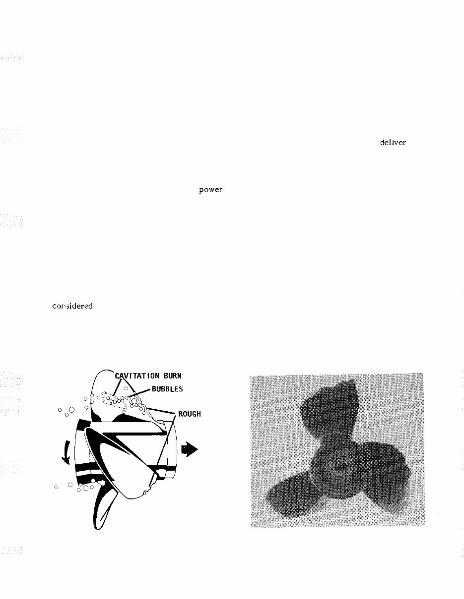
Cavitation (air bubbles) formed at the propeller.
Manufacturers are constantly fighting this problem, as
explained in the text.
ensure the engine will achieve full horse -
power and operate efficiently and safely.
To test for the correct propeller, make a
test run in a body of smooth water with the
lower unit in forward gear at full throttle.
If the reading is above the manufacturer's
recommended operating range, try propel -
lers of greater pitch, until one is found
allowing the powerhead to operate continu -
ally within the recommended full throttle
range.
If the engine is unable to del~ver top
performance and the powerhead is properly
tuned, then the propeller may not be to
blame. Operating conditions have a marked
effect on performance. For instance, an
engine will lose rpm when run in very cold
water. It will also lose rpm when run in salt
water as compared with fresh water. A hot,
low - barometer day will also cause the en -
gine to lose power.
Cavitation
Cavitation is the forming of voids in the
water just ahead of the propeller blades.
Marine propulsion designers are constantly
fighting the battle against the formation of
these voids due to excessive blade tip speed
and engine wear. The voids may be filled
with air or water vapor, or they may actual -
ly be a partial vacuum. Cavitation may be
caused by installing a piece of equipment
too close to the lower unit, such as the knot
indicator pickup, depth sounder, or bait tank
pickup.
Example of a damaged propeller. This unit should
have been replaced long before this amount of damage
was sustained.
(c) PDF Manual Publisher
PROPELLERS 1 - 5
Vibration
The propeller should be checked reg -
ularly to ensure all blades are in good condi -
tion. If any of the blades become bent or
nicked, this condition will set up vibrations
in the drive unit and the motor. If the
vibration becomes very serious it will cause
a loss of power, efficiency, and boat perfor -
mance. If the vibration is allowed to con -
tinue over a period of time it can have a
damaging effect on many of the operating
parts.
Vibration in boats can never be com -
pletely eliminated, but it can be reduced by
keeping all parts in good working condition
and through proper maintenance and lubri -
cation. Vibration can also be reduced in
some cases by increasing the number of
blades. For this reason, many racers use
two - blade props and luxury cruisers have
four - and five - blade props installed.
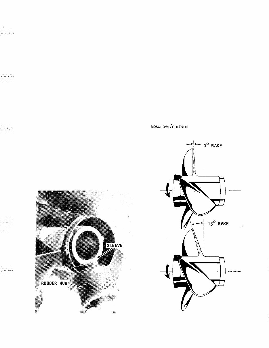
Shock Absorbers
The shock absorber in the propeller plays
a very important role in protecting the
shafting, gears, and engine against the shock
of a blow, should the propeller strike an
underwater object. The shock absorber al -
lows the propeller to stop rotating at the
instant of impact while the power train
continues turning.
Rubber hub removed from the propeller because the
hub was slipping in the propeller.
How much impact the propeller is able
to withstand, before causing the shock ab -
sorber to slip, is calculated to be more than
the force needed to propel the boat, but lets
than the amount that could damage any part
of the power train. Under normal propulsion
loads of moving the boat through the water,
the hub will not slip. However, it will slip if
the propeller strikes an object with a force
that would be great enough to stop any part
of the power train.
If the power train was to absorb an
impact great enough to stop rotation, even
for an instant, something would have to
give, resulting in severe damage. If a
propeller is subjected to repeated striking of
underwater objects, it would eventually slip
on its clutch hub under normal loads. If the
propeller should start to slip, a new shock
absorber/cushion hub would have to be in-
stalled.
Illustration depicting the rake of a propeller, as
explained in the text.
(c) PDF Manual Publisher
You're Reading a Preview
What's Included?
Fast Download Speeds
Online & Offline Access
Access PDF Contents & Bookmarks
Full Search Facility
Print one or all pages of your manual
$33.99
Viewed 50 Times Today


Secure transaction
What's Included?
Fast Download Speeds
Online & Offline Access
Access PDF Contents & Bookmarks
Full Search Facility
Print one or all pages of your manual
$33.99
- The 1966-1983 Chrysler Marine 3.5-140HP Engines Service & Repair Manual is a comprehensive technical manual designed for servicing, maintaining, troubleshooting, and replacing engine components.
- It includes step-by-step instructions, clear images, and exploded-view illustrations sourced from the manufacturer, making it suitable for both professional mechanics and DIY enthusiasts.
- This manual encompasses all troubleshooting and replacement procedures, torque specifications, and detailed images necessary for diagnosing, repairing, or overhauling the engine efficiently.
- It offers the convenience of easy access, searchability, and portability, making it more practical than traditional bound manuals. It is also printable for those who prefer physical copies.
- Printable: Yes
- Language: English
- Compatibility: Compatible with various electronic devices, including PC & Mac computers, Android and Apple smartphones & tablets, etc.
- Requirements: Adobe Reader (free)


