

CAR HAULER TRAILER PLANS FLAT BED
What's Included?
Fast Download Speeds
Online & Offline Access
Access PDF Contents & Bookmarks
Full Search Facility
Print one or all pages of your manual
TABLE OF CONTENTS
TRAILERS
Athletic Trailer ..... ...... .... ... .... ........ .. .. .. ... .... . ........... .. .. .. . ... . .. ..... .. .... .. .... . ... ... ... . . .
Tandem Livestock Trailer .. . .. .... .. ..... . .. .. .... .. . ....... ... .... ..... .. ... . ... . ... .. ... .... . .. .. ... .. ... ... . .
The Design and Construction of a Tandem-Axle Automobile Transporter ....... .. .. .. .. ...... .... ... . ... . .
Design and Fabrication of Heavy-Duty Utilit y Trailer .. .. ..... .... .. ........ . ............ .. .. .. .... .... ..... .
Heavy-Duty Fifth Wheel Agricultural Trailer . .. . ... . ............. . .. ... .. .... ... .. .. .... . .. ..... .. ..... .. ... .
The Comb i nation Machiner y and Hay Trailer . .. .. ... ..... . .. . ... . ... .. ...... .. . ........ . ... .. .... . ..... ... .. .
Two Horse Trailer .. . .... . .. .. ..... . .... .. . ..... . ...... ..... ... . .. .. ... ..... .. ........... ... .. . .. . ....... .. .... . .
6 Ton Flat Bed Equipment Trailer .. .. .............. .. .. ...... . ......... ... ... ... ..... . ... ..... . .. . ..... .. .. .. .
Heavy Dut y Goo se-Neck Trailer .. .. .. . .. . .... .. ..... ... . .. . ..... .. ... . .. .. .. .. .. . ... ..... .. .. ... ....... ... .. . .
Building a Stock Trail er ... . .... .. . .... .. ... . .. ... .. ... .. ...... ....... .. .. .... .. .. . ..... . .... .. ... ... ........... .
A Trailer For Haulin g Carpentry Tools ... . ......... ........... . ........ . .. .. .... . ...... .. .. .. .. .. .... . ... ... . .
Double-Axle Flatbed Tr ailer . . .. .. .. .. .. . .... . .. . ... .. .. . ... .. . .. . ... .. .. .. ..... ... .. .. . ... ........ .. . ..... . . . . .
Tandem Axle, Boa t/ Utility Trailer .. ..... ... .. ... ..... . .. . .. . ............ . ... .. ...... ..... .. ........ . .. .. .. ... .
General Utility T·railer ................ .... .. . .. .. .. ..... .. . .... ... .. . .. . .. . .... . .. . ... . ............ . .. .. ....... .
Goo seneck Tr ailer ......... .... .... . .. .. ..... .. ... . ..... . ..... . ... .. .. ... . ...... ..... . .... . ... . .... . ... .. .. ... .. .
F abrication of a Tilt-Bed Tr ailer ....... ... ... .. . .. . ...... . ...... .. ..... . ...... . ... . .. .. .. . .. .. ..... . ... .. . ... . .
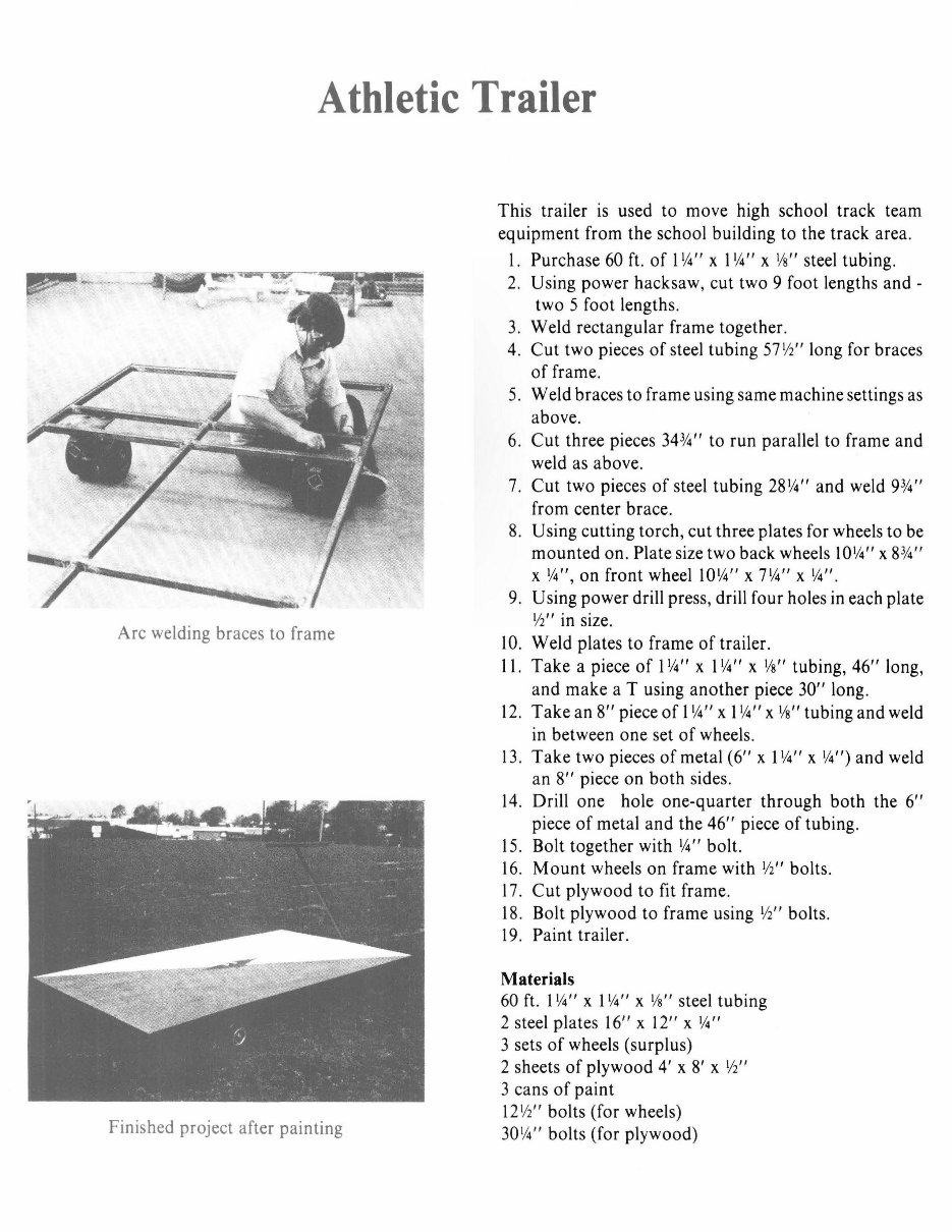
Athletic Trailer
Arc welding braces to frame
Finished project after painting
This trailer is used to move high school track team
equipment from the school building to the track area.
l . Purchase 60 ft. of 1
1
/4 " x l '14" x
1
/s" steel tubing.
2. Using power hacksaw, cut two 9 foot lengths and -
two 5 foot lengths.
3. Weld rectangular frame together.
4. Cut two pieces of steel tubing 57 1/i' ' long for braces
of frame.
5. Weld braces to frame using same machine settings as
above.
6. Cut three pieces 34 314' ' to run parallel to frame and
weld as above.
7. Cut two pieces of steel tubing 28'14" and weld 9314''
from center brace.
8. Using cutting torch, cut three plates for wheels to be
mounted on. Plate size two back wheels 10114'' x 8314' '
x 114'', on front wheel 10114'' x 7114'' x '14".
9. Using power drill press, drill four holes in each plate
1
12 " in size.
10. Weld plates to frame of trailer.
11 . Take a piece of 1114'' x l '14" x Ys" tubing, 46" long,
and make a T using another piece 30" long.
12 . Take an 8" piece of l '14 " x 1114'' x Ys " tubing and weld
in between one set of wheels.
13 . Take two pieces of metal (6" x l '14" x
1
/.i") and weld
an 8" piece on both sides.
14. Drill one hole one-quarter through both the 6"
piece of metal and the 46" piece of tubing.
15. Bolt together with 114'' bolt.
16. Mount wheels on frame with '12'' bolts.
17. Cut plywood to fit frame.
18 . Bolt plywood to frame using '12' ' bolts.
19. Paint trailer.
Materials
60 ft. 1114' ' x 1114'' x Ys " steel tubing
2 steel plates 16" x 12" x '14 "
3 sets of wheels (surplus)
2 sheets of plywood 4' x 8' x Yi''
3 cans of paint
12 1/i'' bolts (for wheels)
30 114'' bolts (for plywood)
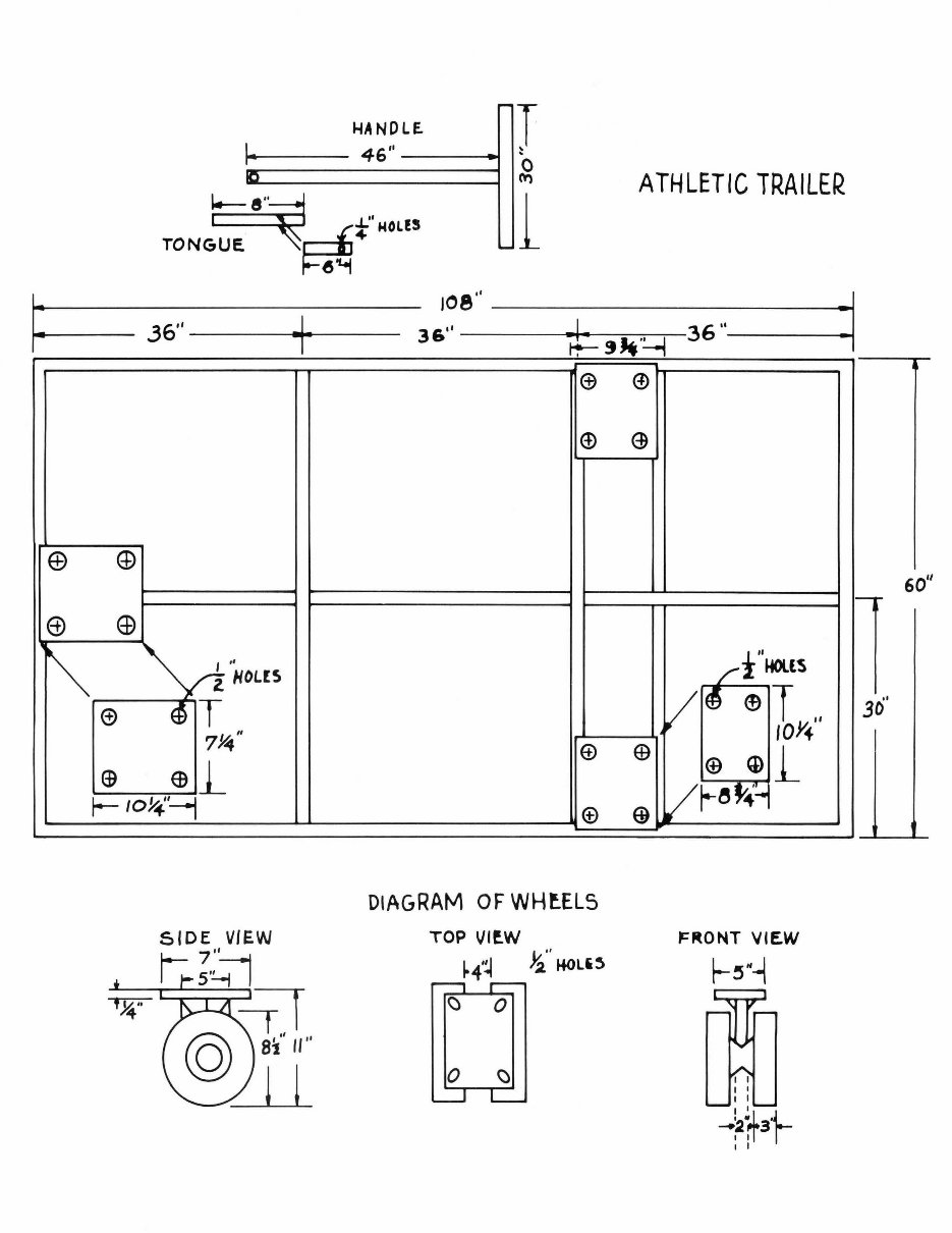
HA ND LE.
I·
46''
___ J
T
~
0
no,
~
TONG~~t" MOLE!
~
l
36''
---t--+-
I ,,
z HOLC5
T
DIAGRAM OF WH~EL5
TOP Vlf.W
~4·~ Ji" HOL'~
ATHLETIC TRAILER
~~ONT VIEW
~!5~-{
I I
I I
I I
I I
~2*3'1-
1 I
60"
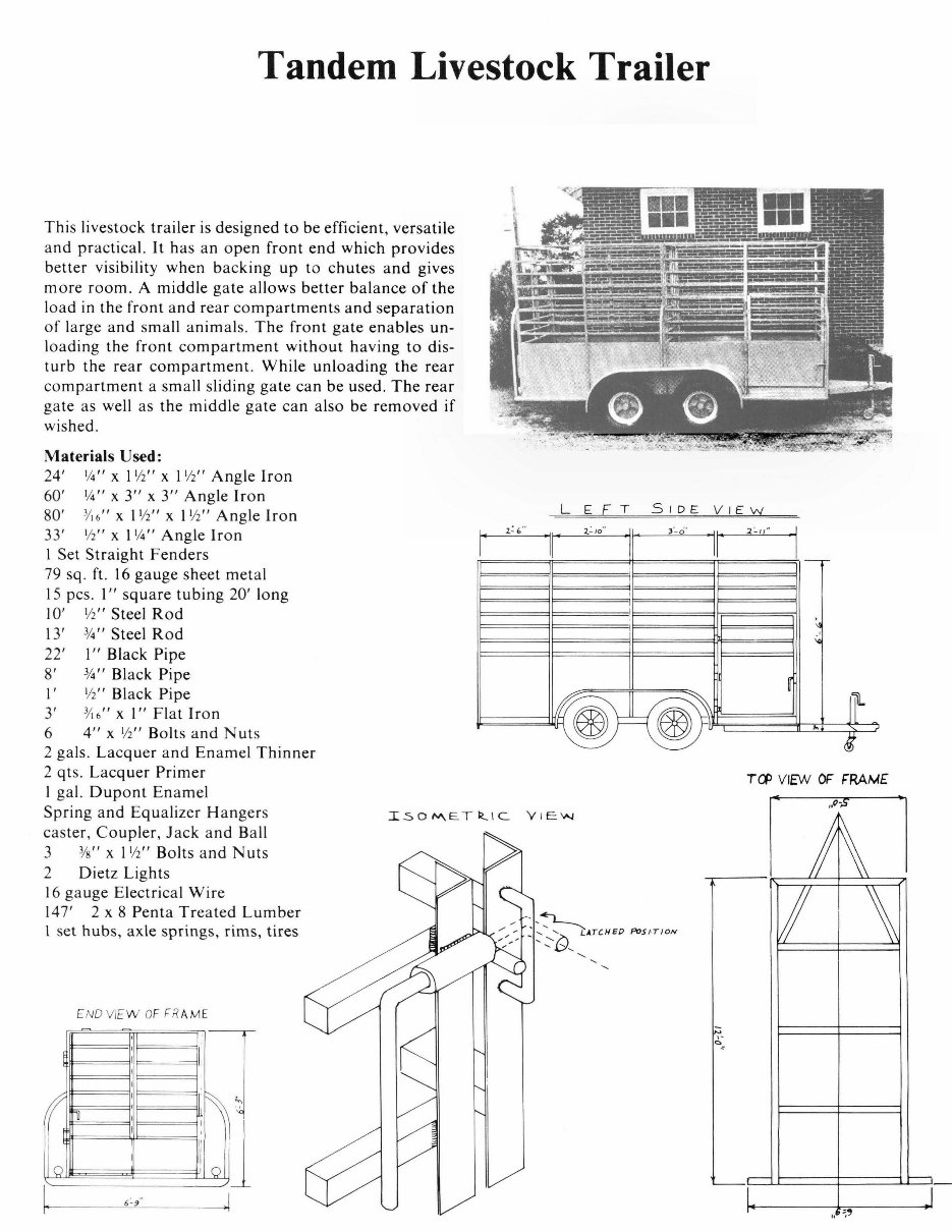
Tandem Livestock Trailer
This livestock trailer is designed to be efficient, versatile
and practical. It has an open front end which provides
better visibility when backing up to chutes and gives
more room . A middle gate allows better balance of the
load in the front and rear compartments and separation
of large and small animals. The front gate enables un-
loading the front compartment without having to dis-
turb the rear compartment. While unloading the rear
compartment a small sliding gate can be used. The rear
gate as well as the middle gate can also be removed if
wished.
Materials Used:
24'
1
/4 " x 1
1
/2
11
x 11/i' ' Angle Iron
60'
1
/4
11
x 3" x 3" Angle Iron
80' 3/ 16
11
x 1
1
/2
11
x I V2
11
Angle Iron
33' V2
11
x 1
1
/4
11
Angle Iron
I Set Straight Fenders
79 sq . ft. 16 gauge sheet metal
15 pcs . I" square tubing 20' long
IO' l/i' ' Steel Rod
13 ' 314'' Steel Rod
22' I" Black Pipe
8' 3/4
11
Black Pipe
l' l/i' ' Black Pipe
3' 3/16
11
x I" Flat Iron
6 4" x l/i' ' Bolts and Nut s
2 gals. Lacquer and Enamel Thinner
2 qt s. Lacquer Primer
I gal. Dupont Enamel
Spring and Equalizer Ha nger s
caster, Coupler , Jack and Ball
3 3/s " x 1
1
/2
11
Bolts a nd Nut s
2 Dietz Lights
16 gauge Electrical Wir e
147 ' 2 x 8 Penta Tre a ted Lumber
l set hubs , axle springs, rim s, tires
f
I
0
ENO VI EW OF FRAME
'
I
I
I
I
I
I
11
I
I
I
6-9
1;
,I
I
'
J
l
1
! 0 i
I
LE FT SIDE VI EW
1 ·
i-i."
II'
2.-10
..
I
: i-0'
I
2' 11"
--
I
I
~
~
I
· @!@
~
..
'
t
T (1) VIEW OF F'RAME
h ~'
The Design and Construction of
A Tandem-Axle Automobile Transporter
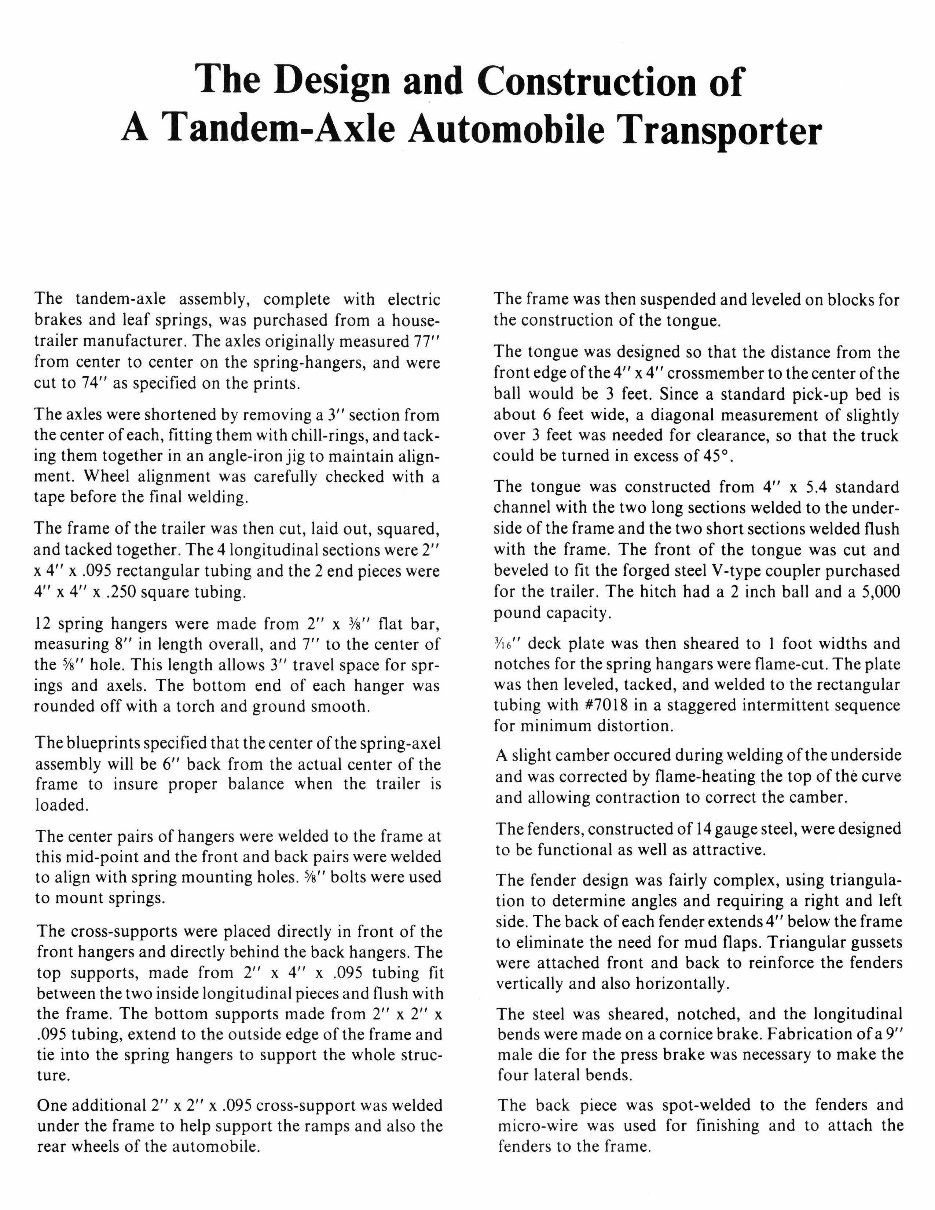
The tandem-axle assembly, complete with electric
brakes and leaf springs, was purchased from a house-
trailer manufacturer. The axles originally measured 77"
from center to center on the spring-hangers, and were
cut to 74" as specified on the prints.
The axles were shortened by removing a 3" section from
the center of each, fitting them with chill-rings, and tack-
ing them together in an angle-iron jig to maintain align-
ment. Wheel alignment was carefully checked with a
tape before the final welding.
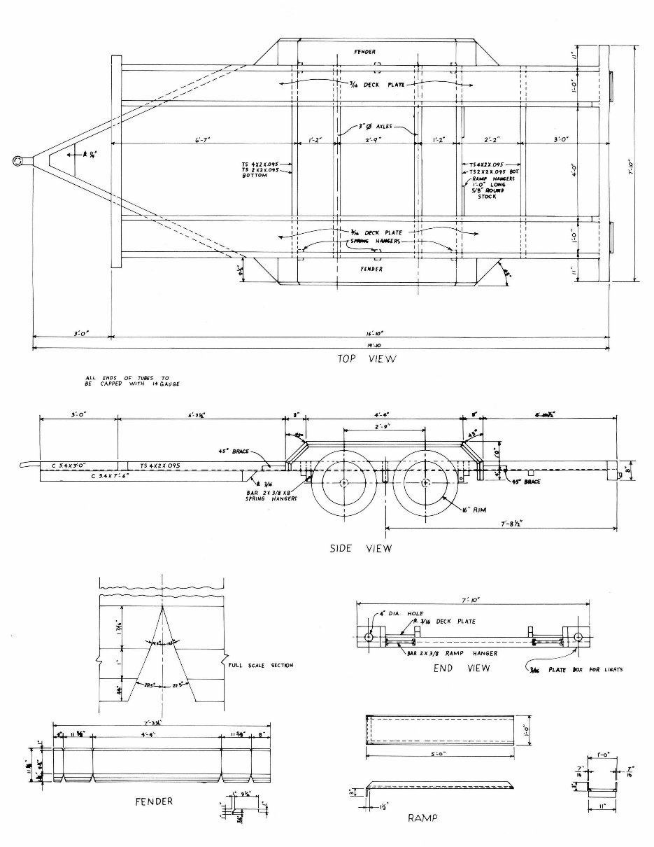
The frame of the trailer was then cut, laid out, squared,
and tacked together. The 4 longitudinal sections were 2"
x 4" x .095 rectangular tub ing and the 2 end pieces were
4" x 4" x .250 square tubing.
12 spring hangers were made from 2" x 3/ s" flat bar,
measuring 8" in length overall, and 7" to the center of
the Ys" hole. This length allows 3" travel space for spr-
ings and axels. The bottom end of each hanger was
rounded off with a torch and ground smooth .
The blueprints specified that the center of the spring-axe!
assembly will be 6" back from the actual center of the
frame to insure proper balance when the trailer is
loaded.
The center pairs of hangers were welded to the frame at
this mid-point and the front and back pairs were welded
to align with spring mounting holes.
5
/s" bolts were used
to mount springs.
The cross-supports were placed directly in front of the
front hangers and directly behind the back hangers. The
top supports, made from 2" x 4" x .095 tubing fit
between the two inside longitudinal pieces and flush with
the frame. The bottom supports made from 2" x 2" x
.095 tubing, extend to the outside edge of the frame and
tie into the spring hangers to support the whole struc-
ture.
One additional 2" x 2" x .095 cross-support was welded
under the frame to help support the ramps and also the
rear wheels of the automobile .
The frame was then suspended and leveled on blocks for
the construction of the tongue.
The tongue was designed so that the distance from the
front edge of the 4" x 4" crossmember to the center of the
ball would be 3 feet. Since a standard pick-up bed is
about 6 feet wide, a diagonal measurement of slightly
over 3 feet was needed for clearance, so that the truck
could be turned in excess of 45°.
The tongue was constructed from 4" x 5.4 standard
channel with the two long sections welded to the under-
side of the frame and the two short sections welded flush
with the frame. The front of the tongue was cut and
beveled to fit the forged steel V-type coupler purchased
for the trailer. The hitch had a 2 inch ball and a 5,000
pound capacity.
3
/ 16
11
deck plate was then sheared to 1 foot widths and
notches for the spring hangars were flame-cut. The plate
was then leveled, tacked, and welded to the rectangular
tubing with #7018 in a staggered intermittent sequence
for minimum distortion.
A slight camber occured during welding of the underside
and was corrected by flame-heating the top of the curve
and allowing contraction to correct the camber.
The fenders, constructed of 14 gauge steel, were designed
to be functional as well as attractive.
The fender design was fairly complex, using triangula-
tion to determine angles and requiring a right and left
side. The back of each fender extends 4" below the frame
to eliminate the need for mud flaps. Triangular gussets
were attached front and back to reinforce the fenders
vertically and also horizontally.
The steel was sheared, notched, and the longitudinal
bends were made on a cornice brake. Fabrication of a 9"
male die for the press brake was necessary to make the
four lateral bends.
The back piece was spot-welded to the fenders and
micro-wire was used for finishing and to attach the
fenders to the frame.
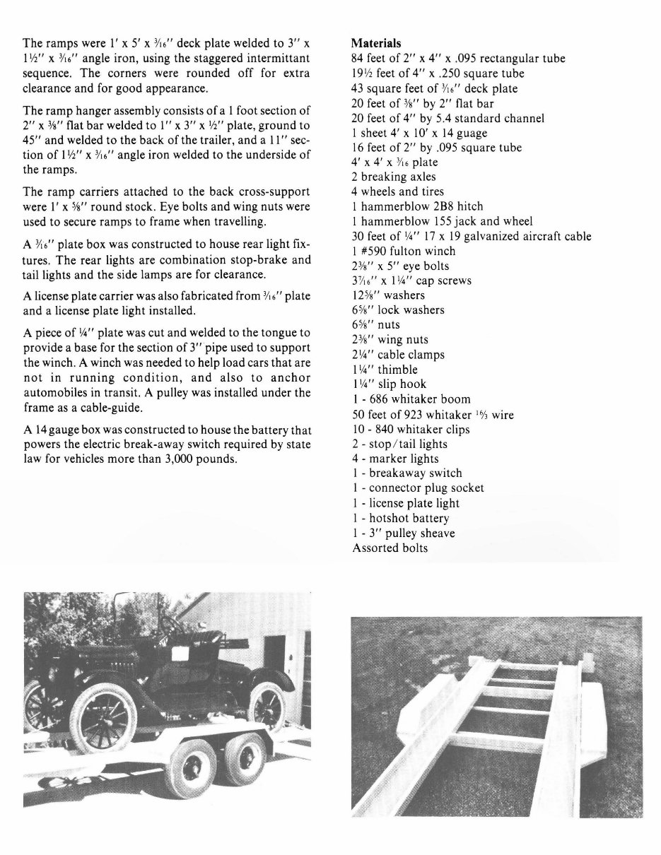
The ramps were 1' x 5' x 3/ 16" deck plate welded to 3" x
11/i' ' x
3
/ 16" angle iron, using the staggered intermittant
sequence. The corners were rounded off for extra
clearance and for good appearance.
The ramp hanger assembly consists of a 1 foot section of
2" x
3
/s" flat bar welded to l" x 3" x l/i'' plate, ground to
45" and welded to the back of the trailer, and a 11" sec-
tion of 1 V2" x :Y16" angle iron welded to the underside of
the ramps .
The ramp carriers attached to the back cross-support
were l' x
5
/s" round stock. Eye bolts and wing nuts were
used to secure ramps to frame when travelling.
A :Y 16" plate box was constructed to house rear light fix-
tures. The rear lights are combination stop-brake and
tail lights and the side lamps are for clearance.
A license plate carrier was also fabricated from
3
/ 16" plate
and a license plate light installed.
A piece of If.I'' plate was cut and welded to the tongue to
provide a base for the section of 3" pipe used to support
the winch. A winch was needed to help load cars that are
not in running condition, and also to anchor
automobiles in transit. A pulley was installed under the
frame as a cable-guide.
A 14 gauge box was constructed to house the battery that
powers the electric break-away switch required by state
law for vehicles more than 3,000 pounds .
Materials
84 feet of 2" x 4" x .095 rectangular tube
19
1
/2 feet of 4" x .250 square tube
43 square feet of
3
/ 16" deck plate
20 feet of 3/s' ' by 2" flat bar
20 feet of 4" by 5.4 standard channel
1 sheet 4' x 10' x 14 guage
16 feet of 2" by .095 square tube
4' x 4' x 3/ 16 plate
2 breaking axles
4 wheels and tires
1 hammerblow 2B8 hitch
l hammerblow 155 jack and wheel
30 feet of
1
/.i " 17 x 19 galvanized aircraft cable
l #590 fulton winch
23/s' ' x 5" eye bolts
31 1 16" x l If.I'' cap screws
12 5/s " washers
6 5/s' ' lock washers
6 5/s " nuts
23/s' ' wing nuts
21/.i'' cable clamps
l If.I'' thimble
l If.I'' slip hook
l - 686 whitaker boom
50 feet of 923 whitaker
1
6/3 wire
l 0 - 840 whitaker clips
2 - stop / tail lights
4 - marker lights
l - breakaway switch
l - connector plug socket
l - license plate light
l - hotshot battery
l - 3" pulley sheave
Assorted bolts
ALL ENO~ OF TU8£S TO
~E CAPPfD WITll 14 GoAUGE
C , .4K 7'. 6'
·•
I
f---.J------1 ·+~ >------ ---<
I
"2$1., . ,________.
I
I
I I
~'fi'•l>fCl
l I I I
TS +x2 (.OfS
rs z i2v: . 09r
BOTTOM
I I o
i' -2'
' I I
l'LATI~ I' I
I I
I I I I
TS·UZX.09.f
TS2X2l .095 901'.
RA.M' HA1115U~
1'-0" LON{;
5te·-,
STOCK
TOP VIEW
FULL SGALf SECTIOM
END VIEW
I
'
'
I
I
I
I I
I
i'-4''
E-- ~--- - __ ___ _______ ]]
Ef1
FEN DER
. ~-
.
.
q::::t-- -- = -~ --- ---~-- ---- __ ,.
~,~·
RAMP
-
0
·'
3·. o·
::
PLAT£ IOX FOR L IGHfS
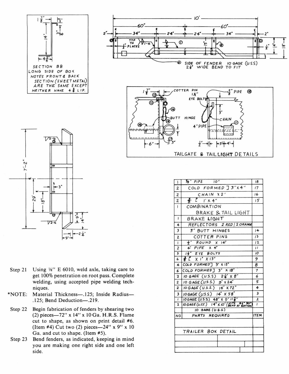
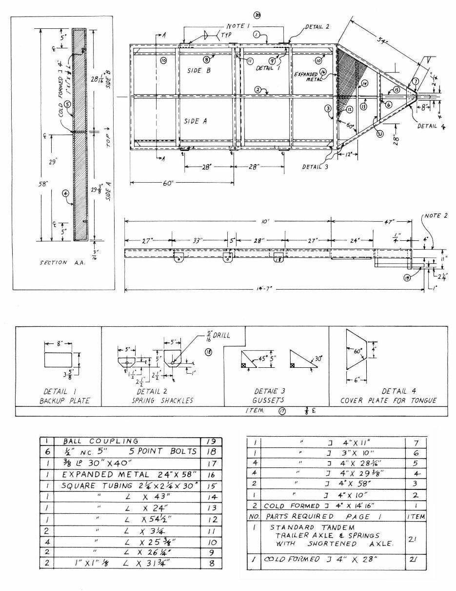
Design and Fabrication of
Heavy-Duty Utility Trailer
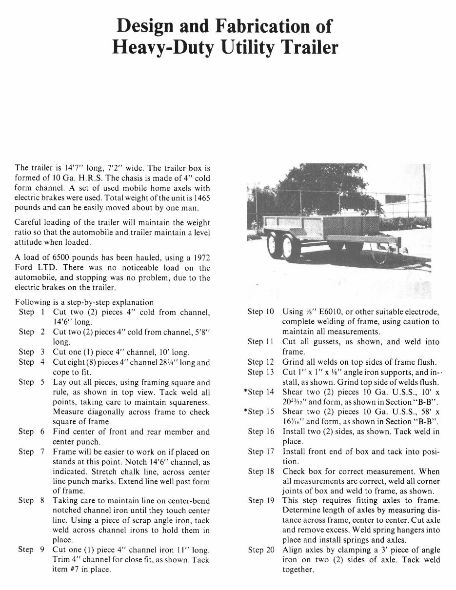
The trailer is 14'7" Jong, 7'2" wide. The trailer box is
formed of 10 Ga. H.R.S. The chasis is made of 4" cold
form channel. A set of used mobile home axels with
electric brakes were used . Total weight of the unit is 1465
pounds and can be easily moved about by one man.
Careful loading of the trailer will maintain the weight
ratio so that the automobile and trailer maintain a level
attitude when loaded .
A load of 6500 pounds has been hauled, using a 1972
Ford LTD. There was no noticeable load on the
automobile, and stopping was no problem, due to the
electric brakes on the trailer.
Following is a step-by-step explanation
Step 1 Cut two (2) pieces 4
11
cold from channel,
14
1
6
11
long.
Step 2 Cut two (2) pieces 4
11
cold from channel , 5'8"
long.
Step 3 Cut one ( 1) piece 4
11
channel, 10' long.
Step 4 Cut eight (8) pieces 4
11
channel 28
1
.4 " long and
cope to fit.
Step 5 Lay out all pieces, using framing square and
rule, as shown in top view . Tack weld all
points , taking care to maintain squareness .
Measure diagonally across frame to check
square of frame.
Step 6 Find center of front and rear member and
center punch.
Step 7 Frame will be easier to work on if placed on
stands at this point. Notch 14
1
6
11
channel, as
indicated. Stretch chalk line, across center
line punch marks. Extend line well past form
of frame.
Step 8 Taking care to maintain line on center-bend
notched channel iron until they touch center
line. Using a piece of scrap angle iron, tack
weld across channel irons to hold them in
place.
Step 9 Cut one (I) piece 4
11
channel iron 11
11
long.
Trim 4
11
channel for close fit, as shown. Tack
item #7 in place.
Step 10 Using Vs" E6010, or other suitable electrode,
complete welding of frame, using caution to
maintain all measurements.
Step 11 Cut all gussets, as shown, and weld into
frame.
Step 12 Grind all welds on top sides of frame flush.
Step 13 Cut 1
11
x 1
11
x Vs " angle iron supports, and in- ·
stall, as shown. Grind top side of welds flush .
*Step 14 Shear two (2) pieces 10 Ga. U .S.S ., 10' x
20
2
3/32
11
and form, as shown in Section "B-B" .
*Step 15 Shear two (2) pieces 10 Ga . U .S.S., 58' x
16
3
/ 16
11
and form, as shown in Section "B-B".
Step 16 Install two (2) sides, as shown. Tack weld in
place.
Step 17 Install front end of box and tack into posi-
tion .
Step 18 Check box for correct measurement. When
all measurements are correct, weld all corner
joints of box and weld to frame, as shown.
Step 19 This step requires fitting axles to frame.
Determine length of axles by measuring dis-
tance across frame, center to center. Cut axle
and remove excess. Weld spring hangers into
place and install springs and axles.
Step 20 Align axles by clamping a 3' piece of angle
iron on two (2) sides of axle. Tack weld
together.
1f-j
T
'It-
SECTION 88
LONG SIDE: OF aox
NOTE'S f'RONT4 BACI(
SE'C TION (HI EET METAL)
ARE THE SAME' EXCEPT
Nt:IT11ER "4AVE: fl LIP.
r
Step 21 Using Vs" E 6010, weld axle, taking care to
get l 00% penetration on root pass. Complete
welding, using accepted pipe welding tech-
niques.
*NOTE: Material Thickness-.125; Inside Radius-
.125; Bend Deduction-.219.
Step 22 Begin fabrication off enders by shearing two
(2) pieces-72" x 14" x 10 Ga . H.R.S . Flame
cut to shape, as shown on print detail #6.
(Item #4) Cut two (2) pieces-24" x 9" x 10
Ga. and cut to shape. (Item #5).
Step 23 Bend fenders, as indicated, keeping in mind
you are making one right side and one left
side.
SIDE OF FENDER IOGAG£ (U.S.S.)
2t• WIDE BEND TO FIT
f"--1 r- r-Jt-4"-1
TAILGATE i TAILUGHT DETAILS
I
W' PIPE 10 " 18
2 COLD FOR MEO] 3"X4 " 17
2 CHAIN 'X 2' 16
2. !- r
,. x. 4" 15'
I COMBINATION
BRAKE ~TAIL LIGHT
I
BRAKE LIGHT
4 REFLE'CTORS 2 REO / 2 ORANG#.
3 ~"BUTT HINGES I+
2. COTTER PINS /3
I t• ROUND x
,~
I l.
2 +· PIPE' x +· II
3 1t• EYE 80L"TS 10
6
tr
X 1• X13 " 9
4- COLP FORMED] ;• XIS"
8
6 COLD FORMEP J
3· x 1s· 7
2 10 GAGE' (U.5.S) 2¥ )( 8" 6
2 10 GAG£ (u.s.s.) !}" x2+ 5'
2 IOGAGE'(U .S .5 . ) 1+" x n· 4-
3 /06AGE (u.s .s.) 14 x sa· 3
I IOGAGE (U.5 .5 .) 48 " X 9' Ill'" .2.
2 JO GAGE (u.ss:) I 4• '/.. 10
1
( {E. ' /./'o AT.,.~ I
10 GME (lJ .s .s.)
NO. PAFITS REQUIR~O ITEM
TRAILFR 80·X DETAIL
I
I I
I
@
[}fTAIL 2
If
r- --
I
I
@
I
I
I , .<:fl
I
281[~
I
~
2
I
-- - - --------
I
I
I
51 DE A
I
I
-
I
If: Cl..
I
I
I_
1--------
~
- ------- - ---------
I
- -- -- - -----
"
L:o
l--w·
J
28"~
29
[)E'TAIL 3
58'
10 '
+ ]J"--1 s-f-- 28'' ------
-= = = =- ----=-
_______
S'FCrtON A.A.
9•
~1
1s· -,
r-5 "1
l6 OR/LL
r-
5
·1 T @
q.;t
~+
~~
~-w·
~·
t ,. q , •
L t
~ . .]
.38 IT /" 21
1-
2.
DETAIL I DETAIL 2 DETAIE J DETAIL 4
BACKUP PLAT£ SPP. I NG SHACKLES GUSSETS COVER PLATE FOR TONGUE
I TEM
@ £
I 8ALL COUPLING 19
I
,,
J 4" x 11"
7
6 ~ " NC 5" 5 POINT 80L TS 18
I
~
] 3"X 10" 6
I ~ l! 30" X40'' 17
4
"
J 4" x 2 8./(4 " 5
I £ X PAND£D M £ TAL 24"X 58" 16
~
,,
]
4"X 29~ " 4--
2
"
J 4•x 58" 3
I SQUARE TUBING 2 !( x 2 ~ >< 30 " ) 5'
I " L
x
4311
J~
I
,,
] +"X 10" 2
I " L x 24-'' /3
2 COLD FORMED J +· x 14' 16" I
I
,,
L x. 5 4-'.1. '' 12
NO. PARTS REQUIR £ D PA GE I ITEM
I 5 TA NOA RD TANDEM
TRA.tL£R AXLE 4.. SPRINGS
2..1
WITH 51-!0P.TENEO AXLE".
2 "
L x 3hf._ II
4-
,,
L x 25 ~" JO
2
"
L
x 261'.' 9
2 I" x / '' Jt L x 31 ~" 8
I O'.J LO FOt?M FO J 4" x. 28H 21
You're Reading a Preview
What's Included?
Fast Download Speeds
Online & Offline Access
Access PDF Contents & Bookmarks
Full Search Facility
Print one or all pages of your manual
$31.99
Viewed 16 Times Today


Secure transaction
What's Included?
Fast Download Speeds
Online & Offline Access
Access PDF Contents & Bookmarks
Full Search Facility
Print one or all pages of your manual
$31.99
Nice neatly made 45 paged book on trailer plans.
- Tilt-bed, gooseneck, sports utility, tandem axle
- Boat, double axle flatbed hauling carpentry tools
- Stock, heavy duty goose neck, 6 ton flatbed, two horse
- Combination machinery/hay, heavy duty fifth wheel agricultural
- Heavy duty utility, tandem axel automobile, livestock car hauler flat bed with ramps
Complete instructions, material lists, measured drawings and diagrams.
All pages can be printed out on your own computer. This is a high quality high resolution file.


