Section 1 - General Information 1 - 0 1 - 0 9803/3710-3 Notes:
Page No. Contents Section 1 - General Information 1 - i 1 - i Introduction About This Manual ................................................................................... 1 - 1 Machine Model and Serial Number ..................................................... 1 - 1 Using the Service Manual ................................................................... 1 - 1 Units of Measurement ......................................................................... 1 - 1 Section Numbering .............................................................................. 1 - 1 Left Side, Right Side ............................................................................ 1 - 2 Cross References ................................................................................ 1 - 2 Identifying Your Machine ......................................................................... 1 - 3 Machine Identification Plate ................................................................ 1 - 3 Component Identification Plates .......................................................... 1 - 5 Standard Torque Settings Zinc Plated Fasteners and Dacromet Fasteners ..................................... 1 - 8 Introduction .......................................................................................... 1 - 8 Bolts and Screws ................................................................................. 1 - 8 Hydraulic Connections ........................................................................... 1 - 12 'O' Ring Face Seal System ................................................................ 1 - 12 'Torque Stop' Hose System ............................................................... 1 - 15 Service Tools Numerical List ........................................................................................ 1 - 16 Tool Detail Reference ............................................................................ 1 - 19 Section B - Frame and Bodywork ...................................................... 1 - 19 Section C - Electrics .......................................................................... 1 - 23 Section E - Hydraulics ....................................................................... 1 - 24 Section F - Transmission ................................................................... 1 - 30 Section H - Steering .......................................................................... 1 - 32 Section K - Engine ............................................................................. 1 - 33 Service Consumables Sealing and Retaining Compounds ....................................................... 1 - 34 Terms and Definitions Colour Coding ........................................................................................ 1 - 35 Hydraulic Schematic Colour Codes ................................................... 1 - 35
Section 1 - General Information Page left intentionally blank 1 - ii 1 - ii
Section 1 - General Information 1 - 1 1 - 1 9803/3710-3 Introduction About This Manual Machine Model and Serial Number This manual provides information for the following model(s) in the JCB machine range: – 526 from SN 1182000 – 526S from SN 1182000 – 528-70 from SN 1182000 – 528S from SN 1182000 Using the Service Manual T11-004 This publication is designed for the benefit of JCB Distributor Service Engineers who are receiving, or have received, training by JCB Technical Training Department. These personnel should have a sound knowledge of workshop practice, safety procedures, and general techniques associated with the maintenance and repair of hydraulic earthmoving equipment. The illustrations in this publication are for guidance only. Where the machines differ, the text and/or the illustration will specify. General warnings in Section 2 are repeated throughout the manual, as well as specific warnings. Read all safety statements regularly, so you do not forget them. Renewal of oil seals, gaskets, etc., and any component showing obvious signs of wear or damage is expected as a matter of course. It is expected that components will be cleaned and lubricated where appropriate, and that any opened hose or pipe connections will be blanked to prevent excessive loss of hydraulic fluid and ingress of dirt. Where a torque setting is given as a single figure it may be varied by plus or minus 3%. Torque figures indicated are for dry threads, hence for lubricated threads may be reduced by one third. The manufacturer's policy is one of continuous improvement. The right to change the specification of the machine without notice is reserved. No responsibility will be accepted for discrepancies which may occur between specifications of the machine and the descriptions contained in this publication. Finally, please remember above all else safety must come first! Units of Measurement T1-001_2 In this publication, the S.I. system of units is used. For example, liquid capacities are given in litres. The Imperial units follow in parentheses ( ) eg 28 litres (6 gal). Section Numbering T11-005 The manual is compiled in sections, the first three are numbered and contain information as follows: The remaining sections are alphabetically coded and deal with Dismantling, Overhaul etc. of specific components, for example: Section contents, technical data, circuit descriptions, operation descriptions etc. are inserted at the beginning of each alphabetically coded section. 1 General Information - includes torque settings and service tools. 2 Care and Safety - includes warnings and cautions pertinent to aspects of workshop procedures etc. 3 Maintenance - includes service schedules and recommended lubricants for all the machine. A Attachments B Body and Framework, etc.
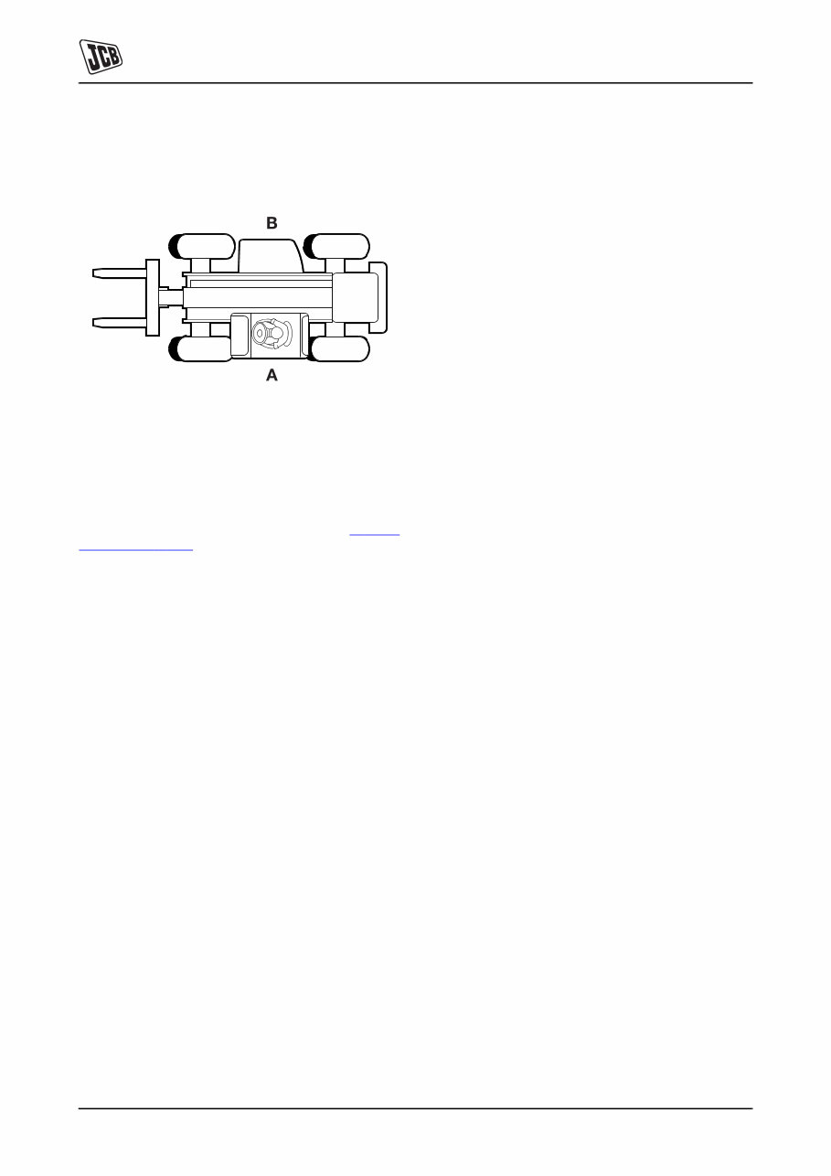
Section 1 - General Information Introduction About This Manual 1 - 2 1 - 2 9803/3710-3 Left Side, Right Side In this manual, 'left' A and 'right' B mean your left and right when you are seated correctly in the machine. Fig 1. Cross References T1-004_2 In this publication, page cross references are made by presenting the subject title printed in bold, italic and underlined. It is preceeded by the 'go to' symbol. The number of the page upon which the subject begins, is indicated within the brackets. For example: K Cross References ( T 1-2) .
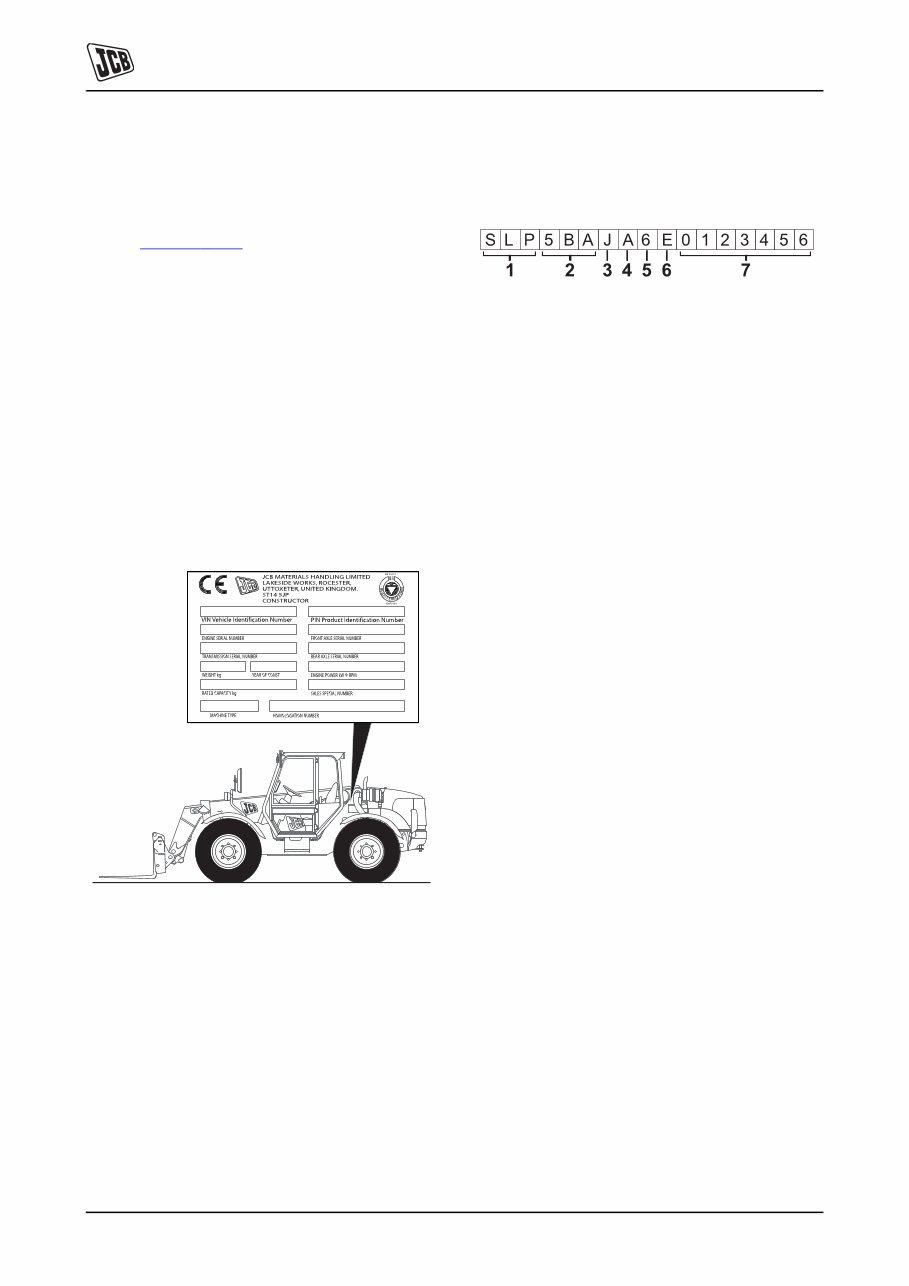
Section 1 - General Information Introduction Identifying Your Machine 1 - 3 1 - 3 9803/3710-3 Identifying Your Machine Machine Identification Plate Your machine has an identification plate mounted as shown. K Fig 2. ( T 1-3) . The serial numbers of the machine and its major units are stamped on the plate. Note: The machine model and build specification is indicated by the VIN (earlier machines) or PIN (later machines). A detailed description of the VIN/PIN numbering system is included later in this section. The serial number of each major unit is also stamped on the unit itself. If a major unit is replaced by a new one, the serial number on the identification plate will be wrong. Either stamp the new number of the unit on the identification plate, or simply stamp out the old number. This will prevent the wrong unit number being quoted when replacement parts are ordered. The machine and engine serial numbers can help identify exactly the type of equipment you have. Fig 2. Typical Vehicle Identification Number (VIN) T011101-2 1 World Manufacturer Identification (3 Digits) 2 Machine Model (3 Digits) 3 Engine Type (1 Digit) 4 Gearbox Model (1 Digit) 5 Year of Manufacture (1 Digit) 6 Manufacturer Location (1 Digit) E = England 7 Machine Serial Number (7 Digits) Each machine has a unique serial number. 5BA = 526 5BC = 526 USA 5BB = 528-70 5BD = 528S JCB Dieselmax: J = SA Build L = SC Build K = SB Build A = 3 Speed C = 4 Speed B = 5 Speed 5 = 2005 7 = 2007 6 = 2006
Section 1 - General Information Introduction Identifying Your Machine 1 - 4 1 - 4 9803/3710-3 Typical Product Identification Number (PIN) T011100-2 1 World Manufacturer Identification (3 Digits) 2 Machine Model (3 Digits) 3 Engine Type (1 Digit) 4 Gearbox Model (1 Digit) 5 Randomly generated check letter (1 Digit) 6 Year of Manufacture (1 Digit) 7 Machine Serial Number (7 Digits) Each machine has a unique serial number. 5BA = 526 5BC = 526 USA 5BB = 528-70 5BD = 528S JCB Dieselmax: J = SA Build L = SC Build K = SB Build A = 3 Speed C = 4 Speed B = 5 Speed 5 = 2005 7 = 2007 6 = 2006 8 = 2008
JCB 526/528 Telescopic Handlers OEM Service & Repair Manual
Models Covered:
JCB 526 (from SN 1182000 and above)
JCB 526S (from SN 1182000 and above)
JCB 528-70 (from SN 1182000 and above)
JCB 528S (from SN 1182000 and above)
This service and repair manual for the JCB 526 and 528 telescopic handlers provides comprehensive technical information for maintaining, diagnosing, and repairing these versatile machines. Tailored to meet factory specifications, it includes step-by-step procedures and recommended service intervals to ensure reliable operation in demanding environments.
The manual covers key components, including the engine, transmission, hydraulics, steering, braking, and electrical systems. Detailed wiring diagrams, torque settings, and exploded parts views are also provided to support both routine maintenance tasks and more complex mechanical repairs. Whether troubleshooting hydraulic issues or performing drivetrain servicing, this guide offers precise, model-specific details.
Designed for digital access, the manual can be viewed on computers and mobile devices, making it convenient for use in workshops or on job sites. Ideal for professional technicians and equipment owners, this service and repair manual is an essential resource for keeping your JCB 526 or 528 telescopic handler in peak working condition.
Printable: Yes Language: English Compatibility: Pretty much any electronic device, incl. PC & Mac computers, Android and Apple smartphones & tablet, etc. Requirements: Adobe Reader (free)
Recently Viewed
5,521,897Happy Clients
2,594,462eManuals
1,120,453Trusted Sellers
15Years in Business
Price:
Actual Price:
JCB 526/528 Telescopic Handlers OEM Service & Repair Manual