663 Telescopic Handler PARTS MANUAL Form No. 913213
913213/AP0204 PRINTED IN U.S.A. Introduction 663 Telescopic Handler The table of contents page shows the page location of various component groups on the machine. When ordering service parts, specify the correct part number, full description, quantity required, and the unit model and serial number. Model and serial numbers for this unit are stamped on a plate located inside the operator’s station. The seri- al number is also stamped on the top front frame. The following reference shows the breakdown of the seri- al number: “Right” and “left” are determined from a position standing behind the unit and facing the direction of travel. GEHL Company reserves the right to make changes or improvements in the design or construction of any part of the unit without incurring the obligation to install such changes on any unit previously delivered. Grease fittings and common attaching hardware, such as cotter pins, set screws, woodruff keys, screws, nuts, etc., are included in the parts list, indented below the part it is (they are) associated with, but NOT illustrat- ed, except where a particular routing or special fas- tening arrangement MUST be maintained. The hard- ware listed is for mounting purposes and is NOT included when the part is ordered for replacement. Standard attaching hardware torque values are pro- vided on the inside Back Cover. Unless otherwise specified, all cap screws are Grade 5, cadmium or zinc plated; hexagon nuts for Grade 5 cap screws or bolts are Grade A. 663 J U 02 4600 Model Year (T=02, U=03, etc.) Month Unit Number Engine
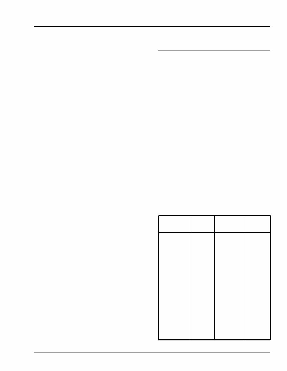
PRINTED IN U.S.A. 1 913213/AP0204 663 Telescopic Handler Introduction List of Abbreviations Used in this Manual AN Acorn Nut AR As Required ASY Assembly BHB Button Head Bolt CB Carriage Bolt CN Castellated Nut CYL Cylinder CS Cap Screw (Hexagon Head) DIA Diameter FHMS Flat Head Machine FLN Flanged Flexlock Nut FLS Flanged Lock Screw FT Foot or Feet GR Grade HLN Hexlock Nut HYD Hydraulic JD John Deere JN Jam Nut L Lock (Washer) LH Left Hand LT Left N Nut (Plain Hex) NA Not Applicable NSS Not Sold Separately NIN Nylon Insert Lock Nut NPTF National Pipe Threaded Fitting P Plain (Washer) PB Plow Bolt PHS Pan Head Screw RH Right Hand RHMS Round Head Machine Screw RHSMS Round Head Sheet Metal Screw RNF Retained Nut Fastener RT Right SHCS Socket Head Cap Screw SHSS Socket Head Set Screw SFN Serrated Flange Nut SHSS Square Head Set Screw STS Self-Thread Screw Hex. Washer Head THMS Truss-Head Machine Screw TRS Thread Roll Screw W/ With WN Wing Nut Size & Part No. Size & Part No. Description Description #10-32 N L50050 1/4 L L50139 1/4-20 NIN L520003 1/4 P L50137 1/4-20 SFN L50051 5/16 L L50143 5/16-18 N L50230 5/16-18 NIN L520004 5/16 P L50141 5/16-18 RNF L530004 5/16-18 SFN L50056 3/8-16 L L50147 3/8-16 N L50066 3/8-16 NIN L520005 3/8-16 P L50145 3/8-16 SFN L50061 3/8-16 WN L530003 7/16 L L50150 7/16-14 NIN L50517 7/16 P L50149 1/2-13 NIN L520019 1/2 P L50151 5/8 L L50156 5/8-11 N L50081 3/4-10 N L50086 3/4-10 NIN L50519 3/4 P L50147 1-8 JN L50145 TABLE OF STANDARD WASHERS, NUTS FILTER REFERENCE Engine Oil S/N 4658 and up; with JD 4045 Turbo . . . . . . . . L99420 S/N 4868 and up; with JD 4045 Natural Thru S/N 4657; with JD 4039 Turbo . . . . . . . . . . L94746 Thru S/N 4867; with JD 4039 Natural With Perkins Engine. . . . . . . . . . . . . . . . . . . . . . . 078849 Engine Fuel S/N 4366 and up; with JD engine . . . . . . . . . . . . L98978 Thru S/N 4365; with JD engine . . . . . . . . . . . . . . L98600 S/N 4302 and up; with Perkins engine . . . . . . . . L88976 Thru S/N 4301; with Perkins engine . . . . . . . . . . 078850 Engine Air Turbo charged engines . . . . . . . . . . . . . . . . . . . L120037 Naturally Aspirated engines . . . . . . . . . . . . . . . L120054 Transmission Oil . . . . . . . . . . . . . . . . . . . L99184 Hydraulic Oil . . . . . . . . . . . . . . . . . . . . . . L97489 (units with Autotroll). L98725
913213/AP0204 4 PRINTED IN U.S.A. GENERAL INFORMATION Decal locations information is provided to assist in the proper selection and application of new decals, in the event the original decals become damaged or the machine is repainted. For correct replacement of decals compare the loca- tion illustrations to your machine before starting to refinish the unit. Check off each required decal using the illustration reference number to find the part num- ber, description and quantity in the list. Refer to the appropriate illustrations for replacement locations. NEW DECAL APPLICATION Before applying the new decals, surfaces must be free from dirt, dust, grease and other foreign material. To apply a solid-formed decal, remove the smaller por- tion of the decal backing paper and apply this part of the exposed adhesive backing to the clean surface while maintaining proper position and alignment. Slowly peel off the other portion of the backing paper while applying hand pressure to smooth out decal sur- face. To apply a die-cut decal, first remove the back- ing paper. Then, properly orient and position the decal onto the clean mounting surface. After the decal is firmly applied and smoothly pressed down, remove the front covering paper. PAINT FINISH Use this list to order paint for refinishing: Units Thru S/N 4310 903891 Six (12 oz. Spray Cans) Industrial Yellow Units S/N 4311 and up 906213 One gallon Construction Yellow 906317 One gallon Charcoal Paint 906323 One quart Charcoal Gray 906214 Six (12 oz. Spray Can) Constr. Yellow 906318 Six (12 oz. Spray Can) Charcoal Gray Decal Kits L500174 Thru S/N 4310 L98860 S/N 4311 and up NOTE: Decals may be purchased in kits or individually. CAUTION ALWAYS read and follow the safety precau- tions on decals. Replace decals if they are damaged, or if the unit is repainted. If repaint- ing, BE SURE that all applicable decals are affixed in their proper locations. Decals 663 Telescopic Handler
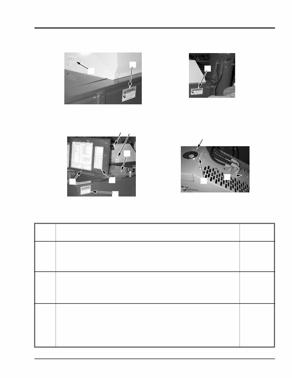
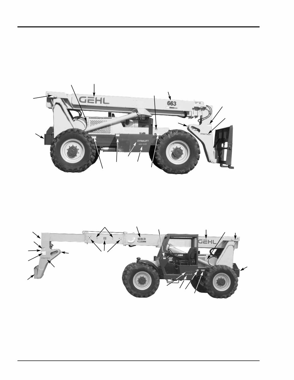
PRINTED IN U.S.A. 5 913213/AP0204 663 Telescopic Handler Decals 2 2 1 3 4 8 5 9 10 1 REF. DESCRIPTION 663 NO. PART NO. 01 GREASE DAILY L65920 02 WARNING - PINCH POINT L65927 03 LUBE CHART L65931 04 FILTER CHART (S/N 4311 and up) L68083 05 WARNING - NO RIDERS L65932 06 HYDRAULIC OIL FILL 072794 07 HYDRAULIC OIL LEVEL L65921 08 DIESEL FUEL 072797 09 COOLANT UNDER PRESSURE 072798 10 ANTI-FREEZE 056859 DECAL LOCATIONS - FRAME AND CHASIS 6 7 FRONT COVER AND FRAME - LEFT SIDE REAR COVER AND FRAME - LEFT SIDE RIGHT SIDE - TOOL BOX AND FUEL TANK REAR COVER - TOP
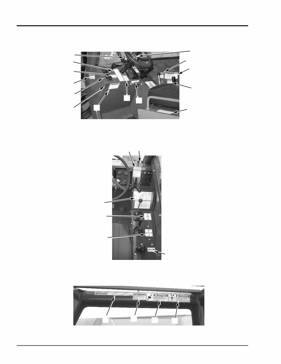
913213/AP0204 6 PRINTED IN U.S.A. Decals 663 Telescopic Handler 8 11 2 3 21 12 15 14 13 5 20 1 22 6 7 9 10 19 16 17 18 4 a OPERATOR’S STATION - DASH AREA OPERATOR’S STATION - CONTROL PANEL OPERATOR’S STATION - UPPER RIGHT CAB AREA DECAL LOCATIONS - OPERATOR’S STATION 4 b 23
PRINTED IN U.S.A. 7 913213/AP0204 663 Telescopic Handler Decals REF. DESCRIPTION 663 NO. PART NO. 01 DANGER - PERSONNEL LIFT L65928 02 WARNING - OPERATOR L63690 03 STEER SELECT L64814 04 a F-N-R SHIFT (attached to shifter) L68295 04 b F-N-R SHIFT (attached to panel next to shifter) (not shown) L60936 1-2-3 SHIFT (attached to panel next to shifter) (not shown) L64945 05 STEERING WHEEL 2.0” DIA. 101545 06 HYDRAULIC PRESSURE SETTINGS L64643 07 WARNING - PARK BRAKE L65925 08 c STANDARD CARRIAGE LOAD CHART L66596 ROTATING CARRIAGE LOAD CHART L66599 BUCKET LOAD CHART L66600 TRUSS BOOM LOAD CHART L66602 WINCH LOAD CHART L66601 09 ATTACHMENT CONTROL L65208 10 BOOM CONTROL L64812 11 FRAME LEVEL CONTROL L64810 12 MADE IN USA 137654 13 a IGNITION/START/HORN L68513 IGNITION/HORN L68052 13 b IGNITION/START BUTTON L64815 PARK BRAKE LIGHT / HORN BUTTON L64816 14 WARNING - SEAT BELT L65440 15 OPERATOR MANUAL INSIDE L65922 16 WARNING - CARRY LOAD LOW 093475 17 WARNING - MACHINE LEVEL L65930 18 DANGER - HIGH VOLTAGE L65929 19 DANGER - PANEL IN PLACE L65948 20 WARNING - TRUSS BOOM TILT L66042 21 WARNING NO RIDERS L65932 22 BRAKE FLUID LEVEL L65934 23 WARNING - BACKUP ALARM L500445 00 CLUTCH DUMP (not shown) L64797 a S/N 4306 and up b Thru S/N 4305 c For a complete set of load chart decals including the metal load chart plates, u-bolts and nuts; order part #L66603 Loadchart Assembly DECAL LOCATIONS - OPERATOR’S STATION
This is the complete parts manual for the GEHL 663 Telescopic Handler.
It contains all the information needed to properly replace parts on the GEHL 663 Telescopic Handler. Filled with illustrations and all part numbers, along with step-by-step instructions and highly detailed exploded pictures and diagrams to show how to complete the required job correctly and efficiently. It's the same type of manual that professional mechanics and DIY enthusiasts would use.
Table of Contents:
INTRODUCTION
OPERATOR'S STATION
CHASSIS, COVERS & TANKS
POWER TRAIN
AXLES
BOOM COMPONENTS
HYDRAULIC SYSTEMS
HYDRAULIC COMPONENTS
AUTOTROLL
NUMERICAL INDEX
TORQUE SPECIFICATIONS
Model Specification: GEHL 663 Telescopic Handler
Language: English
Total Pages: 142
File Format: PDF
Requirements: Adobe Reader
Compatible: All Versions of Windows & Mac, APP ISO, Iphone, Ipad, Android etc...
This quality manual is 100% complete and intact, with no missing/corrupt pages/sections.
This file is bookmarked and searchable to make finding what you need easy.
Detailed illustrations, exploded diagrams, drawings, and photos guide through every service repair procedure.
This manual can be viewed on any computer, as well as zoomed and printed.
Complete manual comes in PDF format, which can work under all PC-based Windows operating systems and Mac as well. It saves to the hard drive and can be burned to CD-ROM.
Instant access means there will be no shipping costs or waiting for a paper or CD manual to arrive in the mail. You will receive this manual today via instant download on completion of payment via our secure payment processor.
We accept all major credit/debit cards and PayPal.