

Tremec T-3650 Transmission Service Manual
What's Included?
Fast Download Speeds
Online & Offline Access
Access PDF Contents & Bookmarks
Full Search Facility
Print one or all pages of your manual
TREMEC
M.R.
INDEX
NOTES, CAUTIONS
WARNINGS&

As you read through the procedures, you will come across NOTES,
CAUTIONS, and WARNINGS. Each one is there for a specific purpose.
NOTES give you added information that will help you to complete a
particular procedure. CAUTIONS are given to prevent you from making
an error that could damage the vehicle. WARNINGS remind you to be
especially careful in those areas where carelessness can cause
personal injury. The following list contains some general WARNING
that you should follow when you work on a vehicle.
Always wear safety glasses for eye protection.
Use safety stands whenever a procedure requires you to be under the
vehicle with the vehicle jacked up.
Be sure that the ignition switch is always in the OFF position, unless
otherwise required by the procedure.
Set the parking brake when working on the vehicle. It should be in
REVERSE (engine OFF) or NEUTRAL (engine ON) unless instructed
otherwise for a specific operation. Place wood blocks (4”X4” or larger)
to the front and rear surfaces of the tires to provide further restraint
from inadvertent vehicle movement.
Operate the engine only in a well-ventilated area to avoid the danger
of carbon monoxide.
Keep yourself and your clothing away from the moving parts, when
the engine is running, especially the fan
and drive belts.
To prevent serious burns, avoid contact with hot metal parts such as
the radiator, exhaust manifold tail pipe, catalytic converter and muffler.
Do not smoke while working on the vehicle.
To avoid injury, always remove rings, watches, loose hanging jewelry,
and loose clothing before beginning to work on a vehicle. Tie long hair
securely behind the head.
Keep hands and other objects clear of the radiator fan blades, Electric
cooling fans can start to operate at any time by an increase in under
hood temperatures, even though the ignition is in the OFF position.
Therefore, care should be taken to ensure that the electric cooling fan
is completely disconnected when working under the hood.
Disconnect the negative battery ground cable before using any electric
welding equipment.
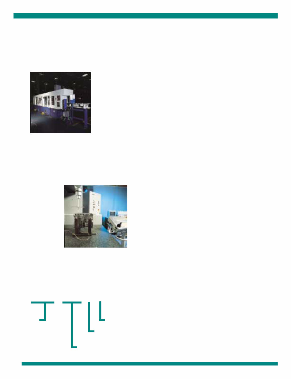
Appropriate service methods
and proper repair procedure are
essential for the safe, reliable
operation of all motor
vehicles as well as the personal
safety of the individual doing
the work.
This Manual provides general
directions for
accomplishing service and
repair work with tested,
effective techniques.
Following them will help assure
reliability.
There are numerous variations
in procedures, techniques,
tools and parts for servicing
vehicles, as well as in the skill
of the individual doing the work.
This Manual cannot possibly
anticipate all such variations
and provide advice or
cautions as to each.
Accordingly, anyone who
departs from the instructions
provided in this Manual must
first establish that he
compromises neither his
personal safety nor the vehicle
integrity by his choice of
methods, tools or
parts.
NOTES, CAUTIONS & WARNINGS
TREMEC
M.R.

3
Introduction 4
Explosive view 5
Transmission Parts 6
Specifications 7
Lubrication 8
General Information 9
Torque Recomendations 10
Axial Clearances 12
Preventive Maintenance 12
Precautions 13
Inspection List 14
Turret Control Disassembly 15
Control Parts Group Disassembly 22
Primary Gear Parts Group Disassembly 24
Secondary Group Disassembly 30
Input Shaft Disassembly 31
Case Parts Group Input Shaft Disassembly 33
Extension Disassembly 36
Reassembly Reverse Gear 38
Troubleshooting Guide 57
Tools 60
CONTENTS
TR-3650
4
INTRODUCTION
This manual is designed to provide detailed information
necessary to service and repair the TREMEC 3650
transmission listed on the cover. As outlined in the Table of
Contents, the manual is divided into 4 main sections:
a) Technical Information and reference
b) Disassembly and reassembly of the transmission
c) Troubleshooting guide
d) Tools required
The format of the manual is designed to be followed in its
entirety if complete disassembly and reassembly of the
transmission is necessary. But if only one component of the
transmission needs to be repaired, see the Table of Con-
tents for the page numbers showing that component. For
example, if you need to work on the Shifting Controls, you
will find instructions for removal, disassembly, and reassem-
bly on page into. Service manuals, Illustrated part list,
drivers instructions, and other forms service information for
theses and other TREMEC transmission are available upon
request.
On any repair or parts replacement, always use “original”
TREMEC parts according to the corresponding “Service
part Catalog”.
The use “non original” parts may endanger the operation
and performance of the transmission.
TRANSMISIONES Y EQUIPOS MECANICOS, S.A. DE C.V.
DOES NOT GUARANTEE service parts or failures resulted
for a misuse or not being provided by an authorized
TREMEC distributor.
A product literature order from, service bulletins (detailing
information on product improvements), repair procedures,
and other service related subjects can be obtained by
writing to the following address:
PLANT AND GENERAL OFFICES:
TRANSMISIONES Y EQUIPOS MECANICOS, S.A. DE C.V.
Av. 5 de Febrero No. 2115
C.P. 76120, Querétaro, Qro.
MEXICO
TR-3650
TREMEC
Design
x10 Capacity nominal lbs-ft
NOMENCLATURE:
Letter designations Number designations
Design Level
Forward speeds
5
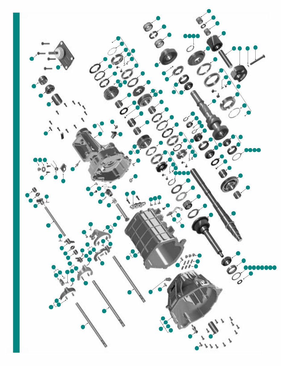
EXPLOSIVE VIEW
71
14
3
129
54
52
48
57
56
65
67
58
130
59
67
6
49
63
129
50
115
113
128
112
132
113
115
113
82
5
4
5
105
113
110
81
60
84
127
127
126
79
114
41
116
66
150
135
136
145
118
119
120
121
122
123
46
11
12
13
16
15
14
17
18
93
70
69
46
42
90
91
106
68
19
20
21
102
43
44
18
146
21
20
19
106
73
46
39
144
138
106
40
102
68
14
99
142
125
147
148
24
25
26
27
28
151
35
141
102
30
38
30
85
140
18
46
86
139
87
112
129
114
129
133
55
53
10
64
80
134
95
111
105
113
33
29
22
72
92
39
23
89
45
18
94
137
37
36
103
100
89
94
89
108
107
117
83
97
109
98
2
104
104
104
104
104
104
129
124
129
104
51
129
113
62
60
61
149
8
40
106
31
32
31
78
75
76
77
74
29
34
45
88
96
1
131
47
6
104
10
7
33
9
138
141
23

TR-3650
6
TRANSMISSION TR-3650 PARTS
1 1 MAGNET
2 1 ROLL PIN
3 8 ROLL PIN
4 1 SNAP RING SPEEDOMETER
5 1 TAG IDENTIFICATION
6 1 CENTER INTERLOCK PIN
7 2 SHIFTER INTERLOCK
8 1 BEARING ROLLER CUP *
9 2 ROLLER BEARING SELECTOR ARM
10 1 SPRING INHIBITOR
11 14 BOLT METRIC HEX WASHER HD
12 2 NYLON STOP
13 1 BEARING INPUT SHAFT POCKET
14 1 THRUST BEARING ASS’Y
15 1 THRUST WASHER SHAFT PILOTED
16 AR SNAP RING 2.30+/-0.05 MM AS REQU.
17 AR SNAP RING 2.40+/-0.05 MM AS REQU.
18 AR SNAP RING 2.50+/-0.05 MM AS REQU.
19 AR SNAP RING 2.60+/-0.05 MM AS REQU.
20 12 SPRING SYNCHRONIZER
21 2 1st. & 2nd. INNER RING
22 2 BLOCKER RING & LINING ASSY 1st. & nd.
23 2 1st. & 2nd. BLOCKER RING
24 1 SNAP RING HUB SYNCHRO 1st. & 2nd.
25 2 SNAP RING TOP INSERT
26 1 BEARING CONE & CUP ASS’Y MAIN SHAFT
27 1 BEARING CONE*
28 AR BEARING SHIM C.S. AS REQUIRED
29 AR BEARING SHIM C.S. AS REQUIRED
30 AR BEARING SHIM C.S. AS REQUIRED
31 AR BEARING SHIM C.S. AS REQUIRED
32 1 BEARING CONE & CUP ASS’Y C.S.
33 1 CUP BEARING *
34 2 ROLLER BEARING GEAR 5th. C.S.
35 2 ROLLER BEARING GEAR REV. IDLER
36 1 SPACER ROLLER BEARING GEAR REV.
37 2 O’RING INHIBITOR
38 1 CONE BEARING*
39 1 BEARING CONE & CUP ASS’Y REAR C.S.
40 1 CUP BEARING REAR C.S.*
41 1 CONE BEARING REAR C.S.*
42 1 SPACER ROLLER BEARING 5th. C.S.
43 1 REVERSE IDLER GEAR
44 2 1st. & 2nd. CLUTCH CONE
45 1 1st. GEAR SPEED ASS’Y M.S.
46 1 1st. GEAR SPEED M.S. *
47 2 BUSHING 3
rd
GEAR & REV.
48 1 CLUTCH HOUSING ASS’Y
49 1 CLUTCH HOUSING *
50 1 TRANSMISSION CASE ASS’Y
51 1 TRANSMISSION CASE *
52 1 EXTENSION ASS’Y
53 1 EXTENSION *
54 1 MAIN SHAFT
55 1 SPEEDOMETER ROTOR GEAR
56 1 OIL SEAL EXTENSION
57 1 INPUT SHAFT
58 1 3
rd
GEAR SPEED. M.S.*
59 1 2nd. GEAR SPEED. ASS’Y M.S.
60 1 2nd. GEAR SPEED. M.S. *
61 1 5th. GEAR SPEED. M.S.
62 1 SYNCHRONIZER ASS’Y 5th. GEAR C.S.
63 1 5th. GEAR C.S. *
64 2 5th: & REVERSE SLEEVE *
65 1 CLUSTER GEAR
66 4 BLOCKER RING 3
rd
/4th./5th & REVERSE
67 1 1st. & 2nd. SHIFT RAIL
68 1 3
rd
& 4 th. SHIFT RAIL
69 1 5th. & REV. SHIFT RAIL
70 1 5th. FORK SHIFT ASS’Y
71 1 5th. FORK SHIFT*
72 1 1st. & 2nd. GATE ASS’Y
73 1 1st. & 2nd. GATE *
74 1 1st. & 2nd. FORK SHIFT ASS’Y
75 1 1st. & 2nd. FORK SHIFT *
76 1 3th. & 4th. FORK SHIFT ASS’Y
77 1 3th. & 4th. FORK SHIFT *
78 1 SELECTOR RAIL
79 1 ARM SELECTOR INHIBITOR
80 1 SEAT SELECTOR GATE
81 4 DETENT PLUG
82 3 DETENT
83 3 ACTUATING SPRING
84 1 REVERSE FORK SHIFT ASS’Y
85 1 REVERSE FORK SHIFT *
86 1 3
rd
& 4th. GATE
87 1 SHIFTER LEVER ASS’Y
88 2 SPACER FONT
89 2 THRUST WASHER 3
rd
GEAR & REV.
90 1 3
rd
& 4th. SYNCHRONIZER ASS’Y
91 1 3
rd
& 4th. SLEEVE *
92 1 1st. & 2nd. SYNCHRONIZER ASS’Y
93 1 1st. & 2nd. SLEEVE*
94 1 SYNCHRONIZER ASS’Y REVERSE GEAR
95 1 REVERSE CLUTCH CONE
96 1 CLUTCH CONE 5th. SPEED. C.S.
97 1 SPRING BASE TURRET
98 1 RAIL REVERSE INHIBITOR
99 1 INHIBITOR REVERSE
100 1 PIN INHIBITOR RETAINER BAR
101 1 INTERLOCK SUPPORT
102 1 OIL SEAL BEARING RETAINER
103 1 WASHER SPRING RETENTION
104 1 GEAR REVERSE M.S.
105 1 THRUST WASHER 5th. GEAR C.S.
106 1 REVERSE SHAFT RAIL
107 1 BOLT M8X1.25X60 TORX BOTTON HEAD
108 1 REVERSE SUPPORT SHAFT
109 1 O’RING
110 12 INSERT SYNCHRONIZER
111 1 3
rd
CLUTCH CONE *
112 1 3
rd
GEAR SPEED ASS’Y M.S.
113 1 1st. & 2nd. HUB SYNCHRO *
114 1 3
rd
& 4th. HUB SYNCHRO *
115 2 5th.. & REV. HUB SYNCHRO *
116 3 BALL
117 1 BALL SPEEDOMETER
118 2 DRAIN PLUG & FILLER PLUG
119 1 BREATHER
120 4 2nd. & 3
rd
NEEDLE BEARING ASS’Y
121 1 BEARING TAPERED ROLLER CUP
122 1 BEARING TAPERED ROLLER CONE
123 1 CAP SCREW HEX HEAD SENSOR
124 1 SWITCH ASS’Y BACKUP LAMP
125 1 TUB RETAINER BEARING*
126 4 DOWEL PIN
127 1 BUSHING EXTENSION HOUSING
128 1 STUD CLUTCH RELEASE LEVER
129 1 SEAL OUTPUT SPLINE
130 AR BEARING SHIM 0.55 +/- 0.013 MM
131 AR BEARING SHIM 0.61 +/- 0.013 MM
132 AR BEARING SHIM 0.66 +/- 0.013 MM
133 AR BEARING SHIM 0.71 +/- 0.013 MM
134 AR BEARING SHIM 0.76 +/- 0.013 MM
135 AR BEARING SHIM 0.81 +/- 0.013 MM
136 AR BEARING SHIM 0.83 +/- 0.013 MM
137 1 SNAP RING
138 1 SPRING CENTERING SHIFT CONTROL
139 2 BOLT SHOULDER
140 14 BOLT METRIC HEX. WASHER HEAD
141 4 BOLT METRIC HEX. WASHER HEAD
142 9 PAD SHIFT FORK
143 1 SENSOR SPEEDOMETER
* SOLD ONLY IN ASS’Y
7
Lengths measured from clutch housing face to cover rear (extension).
Weights include shift bar housing, clutch housing, less shift lever assembly, and
clutch parts. For more information on available application, see the
transmission’s illustrated parts list. All weights are approximate.
Oil capacities are approximate, depending on inclination of engine and transmis-
sion. Always fill transmission, with proper grade and type of lubricant, to level of
filler opening. See LUBRICATION.
SPECIFICATIONS
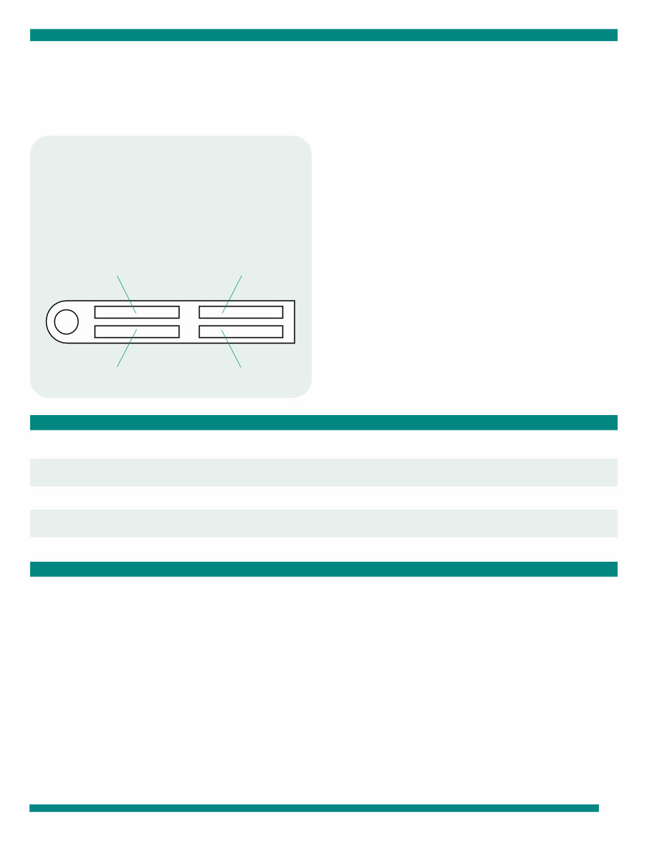
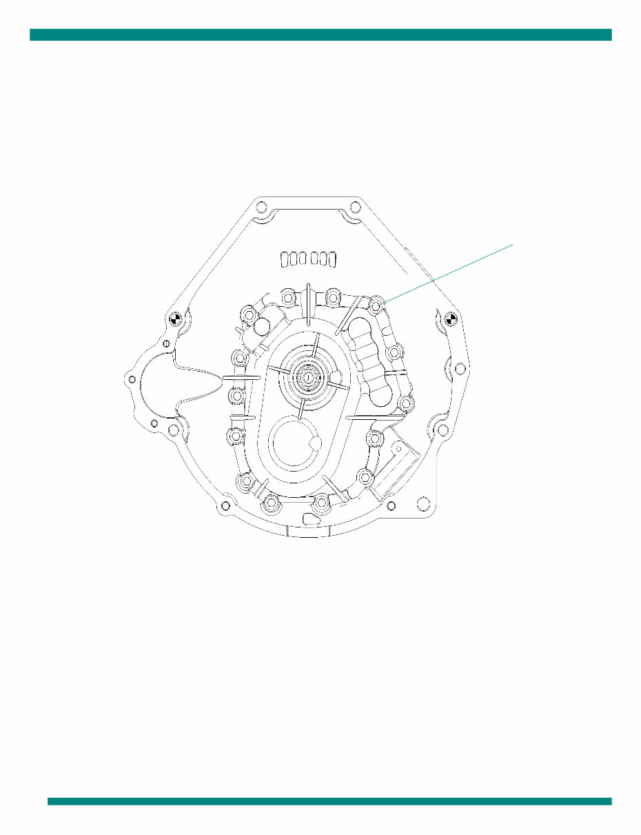
IMPORTANT
All TREMEC transmissions TR-3650 are identified
by the model and serial number, and date. This
information is stamped on the transmission identifi-
cation tag and affixed to the case.
The transmissions series TR-3650 have five forward speeds and one reverse, of advanced design that offers to you, the
most efficent relation of capacity of partorsion-weight, that any other transmissions of 5 speeds within its rank.
NOTES
1
2
3
TRANSMISSION MODEL ASSEMBLY DATE
TRANSMISSION NUMBER SERIAL NUMBER
MODEL GEAR RATIOS
1st. 2nd. 3rd. 4th. 5th. REV. OIL CAPACITY
TR-3650-1/2 3.38 2.00 1.32 1.00 0.67 3.38 3800 C.C.
TR-3650-3/4/5 3.38 2.00 1.32 1.00 0.62 3.38 3800 C.C.
TR-3650
8
Proper lubrication procedures are the key to a good all
around maintenance program.
If the oil is not doing its job, or if the oil level is ignored, all
the maintenance procedures in the world are not going to
keep the transmission running or assure long transmission
life.
TREMEC Transmissions are designed so that the internal
parts operate in an oil circulating bath by the motion of the
gears and shafts.
CHANGE AND INSPECTION OF THE LUBRICANT
Use oil ET-M99 specification.
Additives and friction modifiers are not recommended for
use in transmission TR-3650.
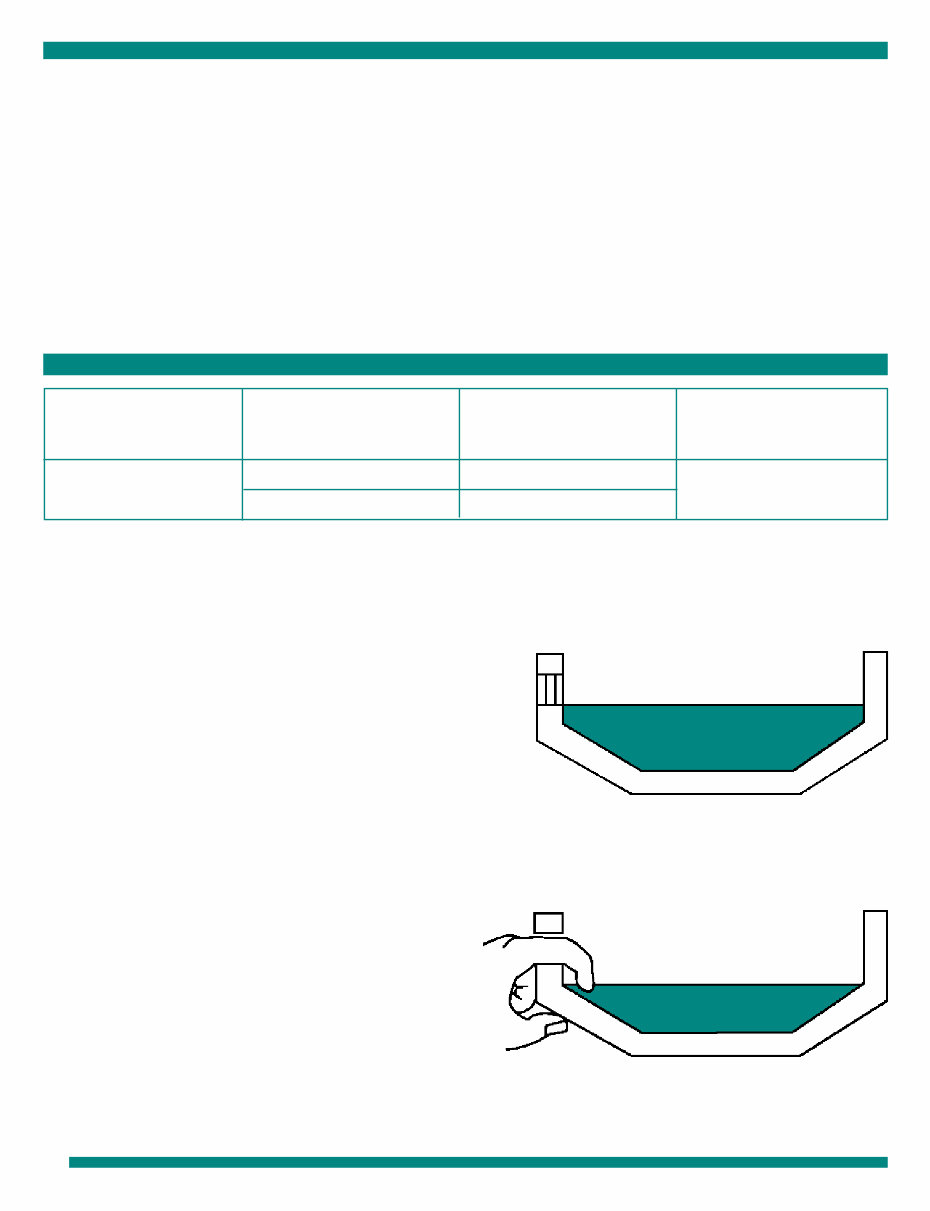
PROPER OIL LEVEL
Make sure oil is level with the filler opening. Because you
can reach oil with your finger does not mean oil is at proper
level.
DRAINING OIL
Drain transmission while oil is warm. To drain oil remove
the drain plug at case bottom.
Clean the drain plug before re-installing.
OIL CHANGE AND REFILLING
Clean case around filler plug and remove plug from case
side. Fill the transmission to the level of the filler opening.
The exact amount of oil depends on the transmission
inclination and model. Do not over fill this causes oil to be
forced out of the case and cause a deficients lubrication.
when adding oil, types and brands of oil should not be
mixed because of possible incompatibility.
LUBRICATION
Thus, all parts are amply lubricated if these procedures are
closely followed:
Maintain oil level. Inspect regularly.
Change oil regularly.
Use the correct grade and type of oil.
Buy from a reputable dealer.
OIL SPECIFICATIONS
MODEL API SPECIFICATION TREMEC OIL
TRANSMISSION SPECIFICATION CAPACITY
TR-3650 Mobil 1 Synthetic ATF ET-M-99 3.8 Lts.
Dexron III 1300-244-006
1
2
3
4
PROPER OIL LEVEL
IMPROPER OIL LEVEL
9
GENERAL INFORMATION GENERAL INFORMATION GENERAL INFORMATION GENERAL INFORMATION GENERAL INFORMATION
The TR-3650 transmissions have five forward speeds and
one reverse, and are shifted as you would shift any
synchronized transmission manual, following the simple 5
speed shift pattern.
Follow the simple 5 speed shift pattern:
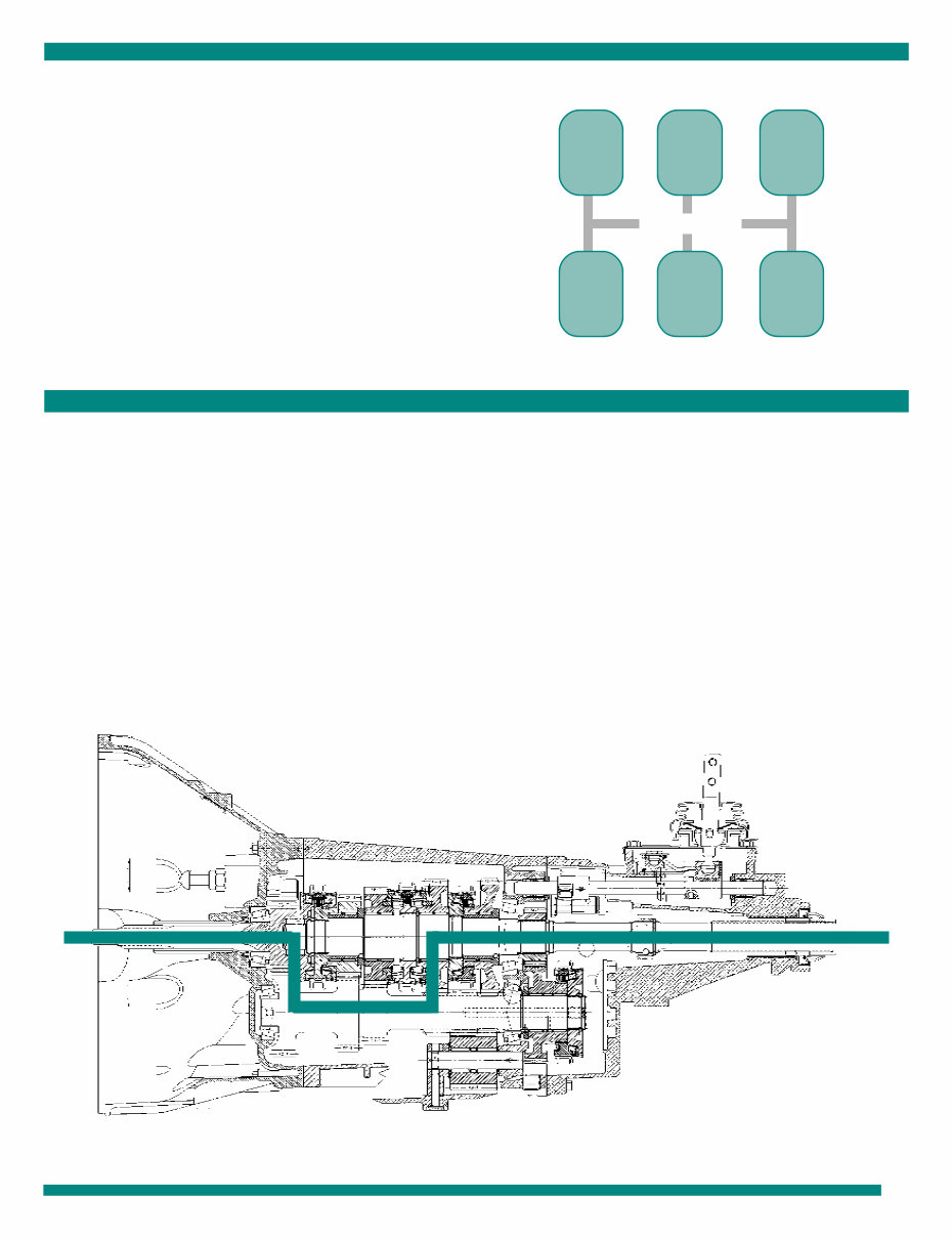
The transmission must efficiently transfer the engine’s
power, in terms of torque, to the vehicle’s rear wheels.
Knowl-edge of what takes place in the transmission during
torque tranfer is essential when troubleshooting and making
repairs.
Power ( torque ) from the engine is transferred to
the input shaft and drive gear.
Torque is transferred to the countershaft drive gear.
POWER FLOW
Torque is delivered along the countershaft to all
countershaft gear.
Torque is transferred to “engaged” mainshaft gear.
The cross section illustrates 1st speed gear position.
Engaged mainshaft gear internal clutching teeth
transfers torque to mainshaft through synchronizer
assembly.
Mainshaft transfers torque directly to driveshaft t
through rear yoke.
1
2
1 3 5
2 4 R
NEUTRAL
3
4
5
6
TR-3650
10
Correct torque application is important to assure long
transmission life. Over or under tightening of fasteners can
result in a loose installation and, in many instances, can
eventually cause demage to the transmission. Use a torque
TORQUE RECOMENDATIONS
wrench to obtain recommended torque ratings. Do not
torque capscrews dry. Apply teflon to threads of all
capscrews before in installing definitive.
2
You're Reading a Preview
What's Included?
Fast Download Speeds
Online & Offline Access
Access PDF Contents & Bookmarks
Full Search Facility
Print one or all pages of your manual
$27.99
Viewed 19 Times Today


Secure transaction
What's Included?
Fast Download Speeds
Online & Offline Access
Access PDF Contents & Bookmarks
Full Search Facility
Print one or all pages of your manual
$27.99
This manual provides detailed information necessary to service and repair the TREMEC T-3650 transmission. The transmission series TR-3650 features five forward speeds and one reverse, offering an efficient capacity-to-weight ratio compared to other 5-speed transmissions.
- Introduction
- Explosive view
- Transmission Parts
- Specifications
- Lubrication
- General Information
- Torque Recommendations
- Axial Clearances
- Preventive Maintenance
- Precautions
- Inspection List
- Turret Control Disassembly
- Control Parts Group Disassembly
- Primary Gear Parts Group Disassembly
- Secondary Group Disassembly
- Input Shaft Disassembly
- Case Parts Group Input Shaft Disassembly
- Extension Disassembly
- Reassembly Reverse Gear
- Troubleshooting Guide
- Tools


