

TOYOTA Transmission G58, R150, R150F, W55, W56 Service Repai
What's Included?
Fast Download Speeds
Online & Offline Access
Access PDF Contents & Bookmarks
Full Search Facility
Print one or all pages of your manual
DISASSEMBLY OF TRANSMISSION
(G58 TRANSMISSION)
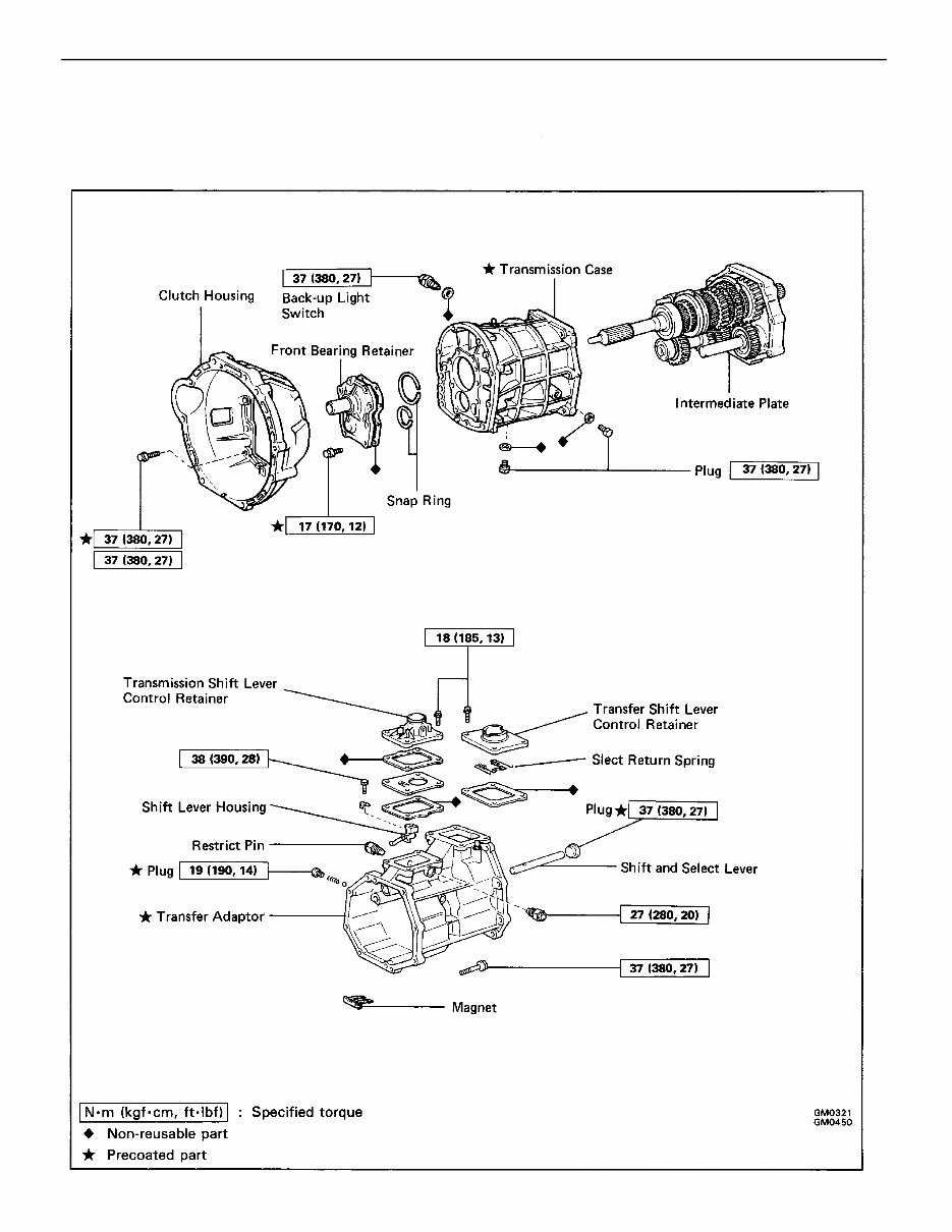
Components
– MANUAL TRANSMISSION Disassembly of Transmission (Components)
MT1–26
Components (Cont’d)
– MANUAL TRANSMISSION Disassembly of Transmission (Components)
MT1–27
Components (Cont’d)
– MANUAL TRANSMISSION Disassembly of Transmission (Components)
MT1–28
4. REMOVE STRAIGHT SCREW PLUG, SPRING AND BALL
(a) Using a torx socket wrench, remove the screw plug
from the transfer adaptor.
(Torx socket wrench T40 09042–00020)
(b) Using a magnetic finger, remove the spring and ball.
5. REMOVE SHIFT LEVER CONTROL RETAINER
(a) Remove the four bolts and transmission shift lever
control retainer.
(b) Remove the four bolts, transfer shift lever control re–
tainer and select return spring.
Disassembly of Transmission
(See pages MT1–26 to 28)
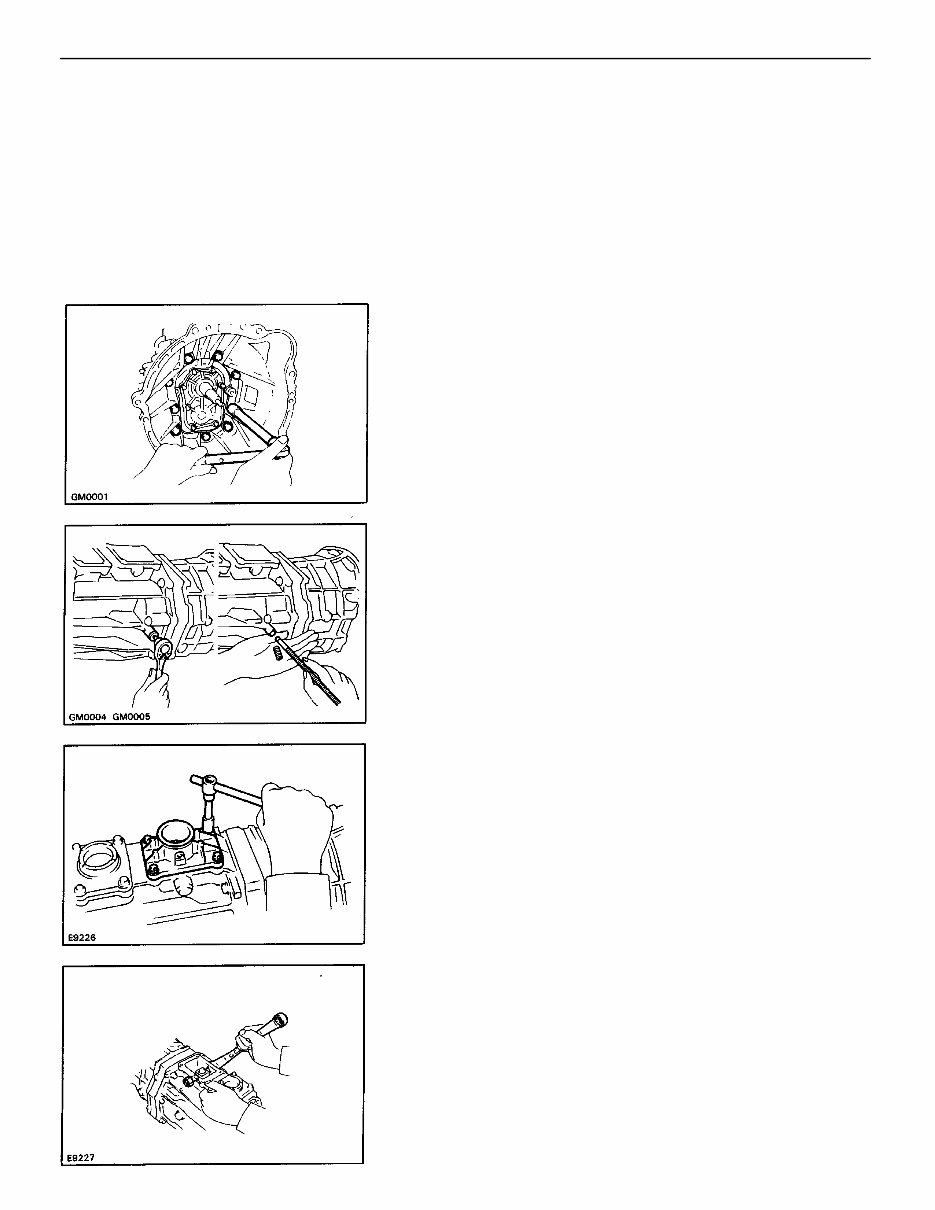
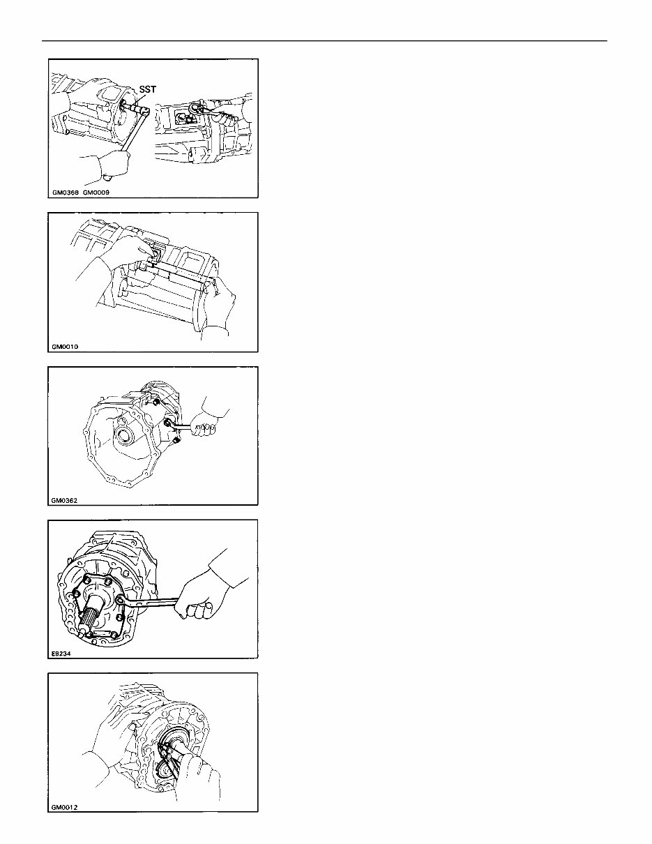
1. REMOVE RELEASE FORK AND BEARING
2. REMOVE BACK–UP LIGHT SWITCH
3. REMOVE CLUTCH HOUSING FROM TRANSMISSION
CASE
Remove the nine bolts and clutch housing.
6. REMOVE RESTRICT PINS
– MANUAL TRANSMISSION Disassembly of Transmission
MT1–29
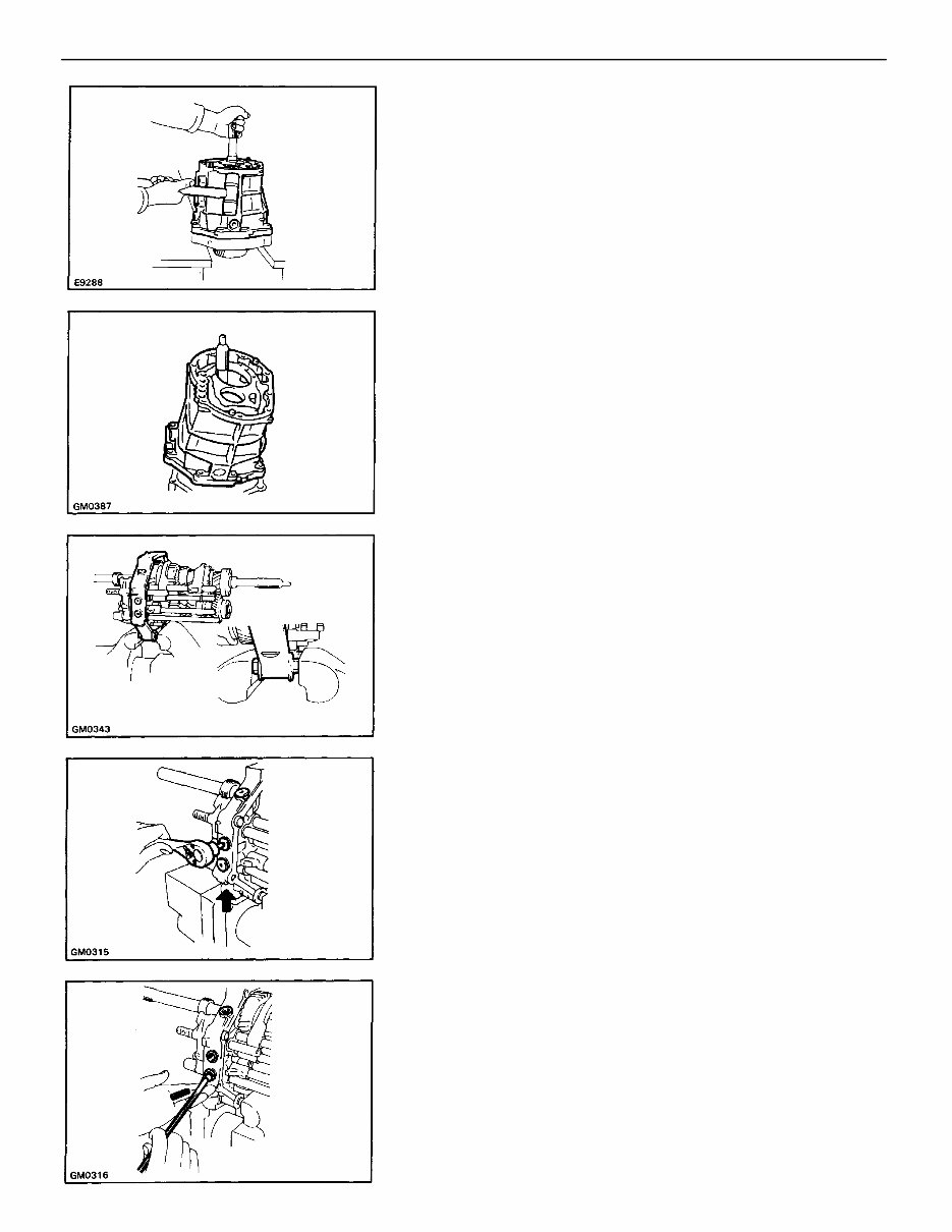
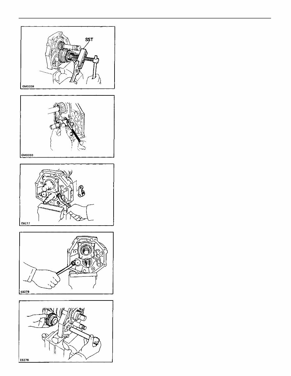
7. REMOVE TRANSFER ADAPTOR
(a) Using SST, remove the plug from the transfer adap–
tor.
SST 09923–00010
(b) Remove the shift lever housing set bolt.
8. REMOVE FRONT BEARING RETAINER
Remove the eight bolts, and remove front bearing re–
tainer and gasket.
(d) Remove the eight bolts.
(e) Using a plastic hammer, carefully tap off the trans–
fer adaptor.
9. REMOVE TWO BEARING SNAP RINGS
Using a snap ring expander, remove the two snap rings.
(c) Remove the shift lever shaft and housing.
– MANUAL TRANSMISSION Disassembly of Transmission
MT1–30
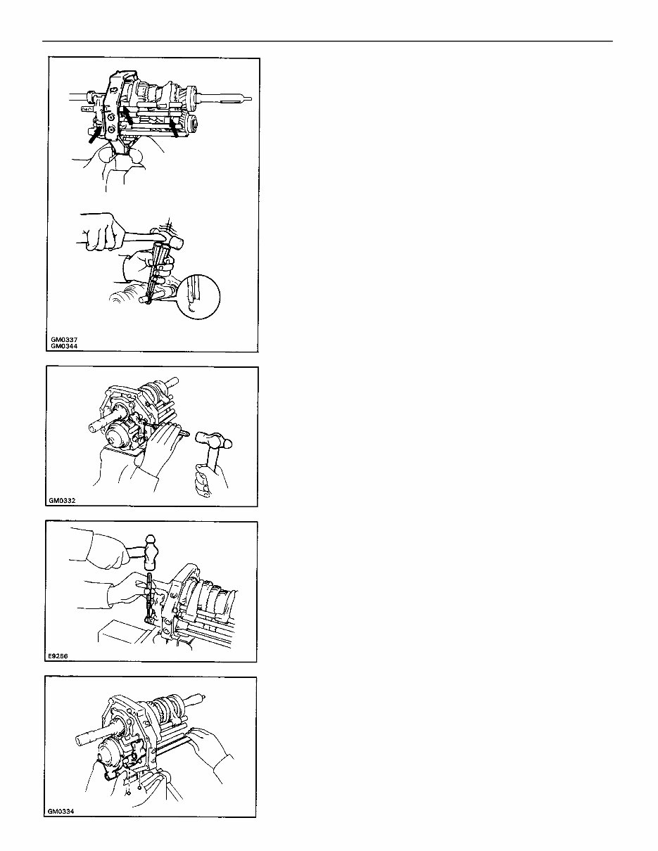
11. MOUNT INTERMEDIATE PLATE IN VISE
(a) Use two clutch housing bolts, plate washers and
suitable nuts as shown.
NOTICE: Install the plate washers in reverse of normal.
Increase or decrease plate washers so that the bolt tip
and front tip surface of the nut are aligned.
(b) Mount the intermediate plate in a vise.
10. SEPARATE INTERMEDIATE PLATE FROM
TRANSMISSION CASE
(a) Stand the transmission as shown.
(b) Using a plastic hammer, carefully tap off the trans–
mission case.
12. REMOVE STRAIGHT SCREW PLUGS, LOCKING BALLS
AND SPRINGS
(a) Using a torx socket wrench, remove the four plugs.
(Torx socket wrench T40 09042–00020)
(c) Remove the transmission case from the intermedi–
ate plate as shown.
(b) Using a magnetic finger, remove the springs and
balls.
– MANUAL TRANSMISSION Disassembly of Transmission
MT1–31
14. REMOVE SHIFT FORK SHAFT NO.5
(a) Using a pin punch and hammer, drive out the slotted
spring pin.
(b) Remove the shift fork shaft No.5.
15. REMOVE SHIFT FORK NO.3, SHIFT FORK SHAFT NO.4
AND REVERSE SHIFT HEAD
(a) Using a pin punch and hammer, drive out the slotted
spring pin.
13. REMOVE SHIFT FORK SHAFT SNAP RINGS
Using two screwdrivers and a hammer drive out the three
snap rings.
(b) Remove the shift fork No.3, shift fork shaft No.4, re–
verse shift head and two balls.
– MANUAL TRANSMISSION Disassembly of Transmission
MT1–32
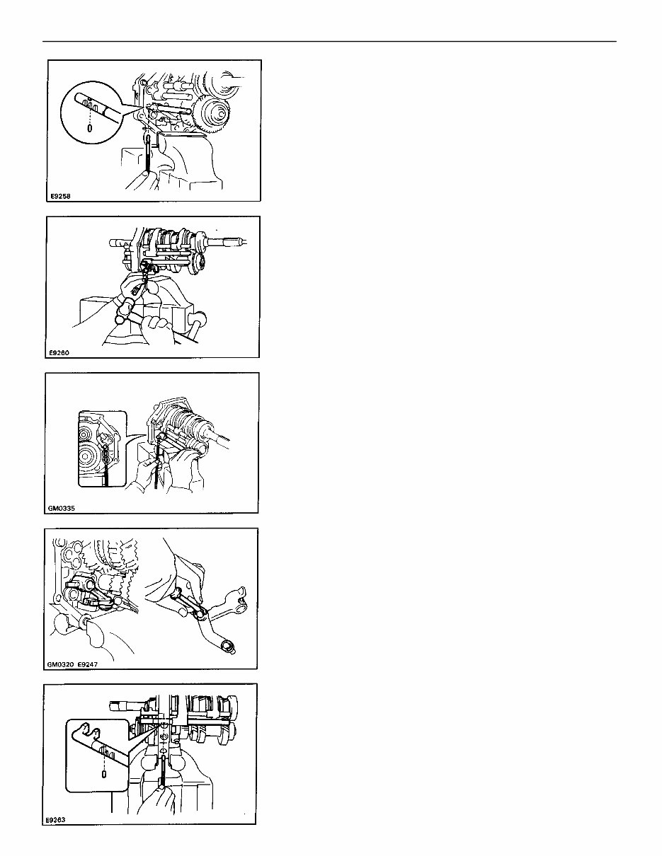
17. REMOVE SHIFT FORK SHAFT NO.1, NO.2 AND SHIFT
FORK NO. 1, NO.2
(a) Using a magnetic finger, remove the interlock pin
No.2 from shift fork shaft No.2.
16. REMOVE REVERSE SHIFT ARM, REVERSE SHIFT FORK
AND SHIFT FORK SHAFT NO–3
(a) Using a magnetic finger–, remove the interlock pin
from shift fork shaft No.3.
(e) Remove the reverse shift arm and fork.
(f) Using a screwdriver, remove the two E–rings.
(g) Separate the shift arm, fork and shoe.
(b) Using a pin punch and hammer, drive out the slotted
spring pin.
(c) Remove the shift fork shaft No.3.
(d) Remove the interlock pin No. 1.
– MANUAL TRANSMISSION Disassembly of Transmission
MT1–33

18. INSPECT COUNTER FIFTH GEAR THRUST CLEARANCE
Using a feeler gauge, measure the counter 5th gear
thrust clearance.
Standard clearance: 0.10 – 0.30 mm
(0.0039 – 0.0118 in.)
Maximum clearance: 0.30 mm (0.0118 in.)
19. REMOVE GEAR SPLINE PIECE NO.5, SYNCHRONIZER
RING, NEEDLE ROLLER BEARINGS AND COUNTER
FIFTH GEAR WITH HUB SLEEVE NO.3
(a) Using two screwdrivers and a hammer, tap out the
snap ring.
(e) Remove the shift fork No. 2 set bolt.
(f) Remove the shift fork No.1, No.2 and shift fork
shaft No.2.
(c) Remove the shift fork shaft No. 1.
(d) Remove the interlock pin No. 1.
(b) Remove the shift fork No. 1 set bolt.
– MANUAL TRANSMISSION Disassembly of Transmission
MT1–34
(b) Using SST, remove the gear spline piece No. 5.
SST 09213–60017 (09213–00020, 09213–00030,
09213–00060)
(c) Remove the synchronizer ring, needle roller bearing
and counter 5th gear.
22. REMOVE REVERSE IDLER GEAR AND SHAFT
(a) Remove the reverse idler gear shaft stopper set bolt
and stopper.
20. REMOVE SPACER AND BALL
(a) Remove the spacer.
(b) Using a magnetic finger, remove the ball.
21. REMOVE REVERSE SHIFT ARM BRACKET
Remove the two bolts and reverse shift arm bracket.
(b) Remove the reverse idler gear and
shaft.
– MANUAL TRANSMISSION Disassembly of Transmission
MT1–35
You're Reading a Preview
What's Included?
Fast Download Speeds
Online & Offline Access
Access PDF Contents & Bookmarks
Full Search Facility
Print one or all pages of your manual
$27.99
$36.99
Viewed 15 Times Today


Secure transaction
What's Included?
Fast Download Speeds
Online & Offline Access
Access PDF Contents & Bookmarks
Full Search Facility
Print one or all pages of your manual
$27.99
$36.99
- Make: TOYOTA
- Model: (not specified)
- G58, R150, R150F, W55, W56 TRANSMISSION
- Pages: 167
- Item: Service Repair Manual
- File Type: PDF
- Bookmarks: yes
Description:
- Operation
- Components
- Inspections
- Assembly
- Components parts removal
- Dissassembly transmission
- Special Tools
- Precautions
- Service Specifications
- Installation Transmission


