

International 6 Plus Transmission Manual SPICER 7 Speed
What's Included?
Fast Download Speeds
Online & Offline Access
Access PDF Contents & Bookmarks
Full Search Facility
Print one or all pages of your manual
TRANSMISSION
TECHNOLOGIES
Corporation
Technology in Motion
®
MODELS
ES52-7B
ES56-7B
ES066-7B
7 SPEED
TRANSMISSION
Service Manual
Bulletin No. 2366
Revised August 2002

Tech Support 1-800-401-9866
TABLE OF CONTENTS
SECTION I — GENERAL INFORMATION
SPECIFICATIONS ......................................................................................................... 1
TORQUE SPECIFICATIONS ......................................................................................... 2
DRIVER INSTRUCTIONS ............................................................................................. 3
SECTION II — MAINTENANCE
LUBRICATION .............................................................................................................. 4
TOOL REFERENCE ..................................................................................................... 5
SECTION III — GENERAL DISASSEMBLY ............................................................................. 6
SECTION IV — SHIFT TOWER DISASSEMBLY ...................................................................... 8
SECTION V — REAR CASE DISASSEMBLY
REAR CASE EXPLODED DRAWING ........................................................................... 9
REAR CASE GEARS EXPLODED DRAWING ............................................................ 10
REAR CASE DISASSEMBLY ...................................................................................... 11
REAR CASE DISASSEMBLY (OPTI-RAIL) ................................................................. 16
SECTION VI — MAIN CASE DISASSEMBLY
MAIN CASE EXPLODED DRAWING .......................................................................... 21
CLUTCH HOUSING & SHIFT FORKS EXPLODED DRAWING ................................. 22
MAIN CASE DISASSEMBLY ....................................................................................... 23
MAIN CASE DISASSEMBLY (OPTI-RAIL) .................................................................. 26
SECTION VII — MAINSHAFT DISASSEMBLY
MAINSHAFT EXPLODED DRAWING ......................................................................... 29
MAINSHAFT DISASSEMBLY ...................................................................................... 30
SECTION VIII — COUNTERSHAFT DISASSEMBLY & REASSEMBLY ................................ 32
SECTION IX — CLEANING & INSPECTION PROCEDURES ............................................... 33
SECTION X — MAINSHAFT REASSEMBLY ......................................................................... 34
SECTION XI — MAIN CASE REASSEMBLY ......................................................................... 36
MAIN CASE REASSEMBLY (OPTI-RAIL) ................................................................... 38
SECTION XII — REAR CASE REASSEMBLY ....................................................................... 41
REAR CASE REASSEMBLY (OPTI-RAIL) .................................................................. 45
SECTION XIII — SHIFT TOWER REASSEMBLY ................................................................... 50
SECTION XIV — TROUBLESHOOTING ................................................................................ 51
Tech Support 1-800-401-9866
GENERAL
INFORMATION
SECTION I
1
Gear Ratios
ES52-7B ES066-7B
ES56-7B
Gear Ratio Ratio % Step
Rev. 8.99 6.66
1st 10.09 7.48
—69—
2nd 5.98 4.43
—61—
3rd 3.72 2.76
—45—
4th 2.56 1.90
—41—
5th 1.81 1.34
—34—
6th 1.35 1.00
—35—
7th 1.00 .074
Specifications
Torque Capacity ........................ ES52-7B - 520 lbs. ft. (704 nm)
ES56-7B - 560 lbs. ft. (758 nm)
ESO66-7B - 660 lbs. ft. (894 nm)
Ratio Coverage .......................... 10:1
Synchronized ............................. Gears 2-7
Length ....................................... 35” (clutch housing mounting face to washer seat face)
Weight ....................................... 454 lbs. (206 kg)
Clutch Housing .......................... SAE No. 2
Clutch ........................................ 13” or 14” single or 2-plate push or pull
Input Shaft ................................. 1 3/4” - 10-spline or 1 1/2” - 10-spline
Lube Capacity ........................... 22 pints (10.4 liters)
Speedometer ............................. Provision for mechanical and electronic
Power Take-Off .......................... 6-bolt right & left, countershaft rear
34 tooth 18° right-hand helix
17.50° pressure angle
PTO Speeds: ............................. % of engine RPM ES52-7B, 48.8%
ES56-7B, 48.8%
ES066-7B, 65.8%
General Application Guidelines
On-Highway Use
ES56-7B
ES52-7B ES066-7B
GVW: 50,000 lbs. 65,000 lbs.
HP Range: 155 - 210 HP 185 - 250 HP
RPM Range: 1,800 - 3,000
Engine Types: 5 - 9 Liter Diesel
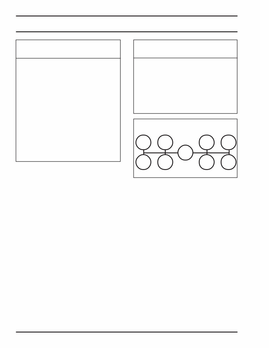
Simple Shift Pattern
R 2 4 6
1 3
N
5 7

Tech Support 1-800-401-9866
GENERAL
INFORMATION
SECTION I
2
TORQUE SPECIFICATIONS FOR NUTS AND CAP SCREWS
Nom. Size (Dia.) Wrench Torque (ft. lbs.)
Part Name
Inches mm Min. Max.
.375 10 Oil trough (16 x .750) 25 41
.375 10 Intermediate shift bar support
(16 x 1.00) 25 41
.375 10 Front mainshaft bearing cap
(16 x 1.00) 25 41
.375 10 Overdrive linkage (16 x 1.00) 25 41
.375 10 Rear mainshaft bearing cap
(16 x 1.125) 25 41
.375 10 Rear countershaft bearing cap
(16 x 1.125) 25 41
.375 10 Clutch housing to main case
(16 x 1.25) 25 41
.375 10 Front shift bar support
(16 x 2.250) 25 41
.438 11 Rear mainshaft brake cap
(14 x 1.25) 40 56
1.062 27 Shift tower trunnion 100 125
.375 10 6-bolt PTO aperture cover 25 41
1.250 32 Mainshaft output nut 300 325
2.548 65 Intermediate mainshaft (spanner) nut 300 325
.875 23 Backup light switch 40 40
Tech Support 1-800-401-9866
GENERAL
INFORMATION
SECTION I
3
How to Shift the Spicer Easy-Shift
7-Speed Transmissions
Synchronizer Information
The purpose of a synchronizer is to simplify shifting and help
deliver clash-free shifts. Only 1st and reverse gears aren’t
synchronized.
To shift, the driver depresses the clutch and moves the lever
toward the desired gear. When the synchronizer ring makes
contact with the desired gear, “blockers” automatically prevent
the shift collar from completing the shift until the gear and
mainshaft speeds are matched. When the speeds are matched,
the synchronizer allows the shift to be completed without
clashing.
Steady pressure on the shift lever helps the synchronizer do
its job. When speeds are synchronized, the lever moves into
gear smoothly and easily. If the driver jabs or “teases” the
synchronizer, the synchronizer can’t do its job. It is possible to
override a blocker if the lever is forced into gear. However, this
defeats the purpose of the synchronizer and can shorten the
life of the transmission.
Driver Instructions
Upshifting
To drive a vehicle containing this transmission, first depress
the clutch and wait for complete release. Next, move the shift
lever into 1st gear and engage the clutch. Accelerate to an
RPM that will allow enough momentum to select the next
higher gear and still have vehicle acceleration after complet-
ing the shift into 2nd gear. This is known as the progressive shift
technique. Using this shift technique saves fuel. There is usually
no reason to go all the way to the governor before you shift to
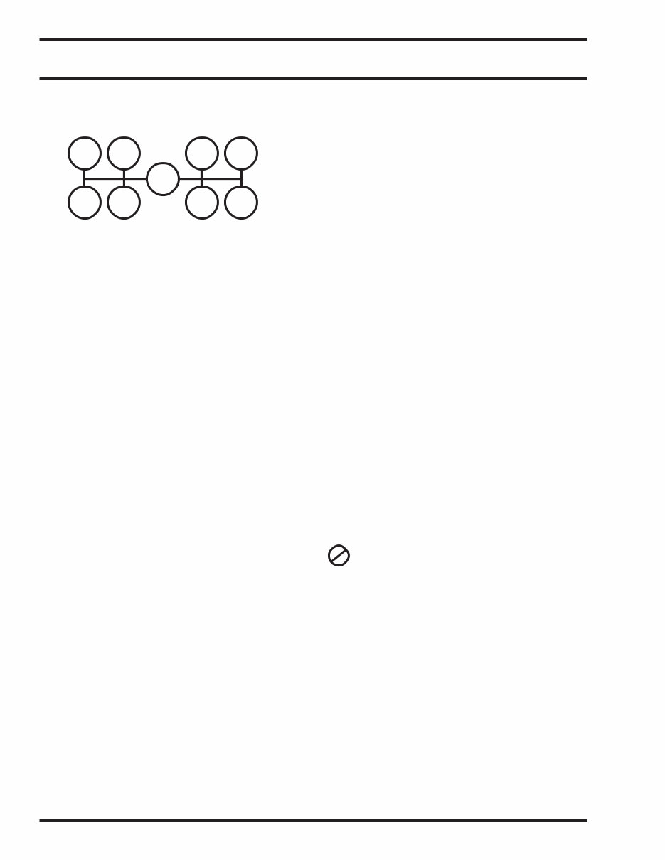
1
R 2
3
N
4
5
6
7
2nd gear. This method can vary depending on the GVW of the
vehicle, road conditions, and type of service.
When 2nd gear is desired, declutch and move the shift lever
toward that gear. The synchronizer will pick up 2nd gear and
synchronize its speed to the mainshaft speed. When synchro-
nized, the lever moves easily into 2nd gear.
Continue in the same manner to top road speed. Notice that as
you approach top road speed you must accelerate close to
the governed speed before allowing the engine to drop to the
next gear shift point. This is because air resistance at higher
speeds requires more of the available horsepower to get
adequate performance. Maximum performance and horse-
power are achieved at governed speed.
Downshifting
To begin downshifting form top gear, declutch and move the
shift lever steadily toward 6th gear and speed it up to the vehicle
speed. This will allow a clash-free shift from 7th to 6th gear. After
the shift, reengage the clutch while accelerating the engine to
keep the vehicle moving at the desired speed. If further
downshifts are required, continue in a similar manner.
Remember that 1st gear isn’t synchronized. Therefore, shift-
ing into gear will require a double clutch operation to complete
a clash-free shift.
Towing
Do not tow vehicles without first pulling the axles
or disconnecting the driveshaft. If you tow the
vehicle without doing this, you can damage drive train
components because the system lubrication is inad-
equate when the vehicle is towed.
Tech Support 1-800-401-9866
4
MAINTENANCE
SECTION II
Lubrication
To insure proper lubrication and operating tem-
peratures in this unit, the proper lubricants
must be used. Correct oil levels must be main-
tained. TTC recommends using only lubricants produced by
reputable, well-known suppliers. If you want to use a lubricant
not specified below, please contact your local truck dealer to
determine whether the lubricant is suitable for your purposes.
Recommended Lubricants
The lubricants listed below are recommended for use in all Spicer
mechanical transmissions, auxiliaries, and transfer cases.
Oil Changes
For off highway use, TTC recommends that the oil be changed
after the first 24 hours of service, but before 100 hours of service
have been completed.
Many factors influence the following oil change periods. There-
fore, a definite mileage interval is not specified here. In general,
a drain and flush should be scheduled at 50,000 miles,
or one-year intervals. If synthetic oil is used, a drain and flush
should be scheduled at 500,000 miles, or 5 year intervals. Off-
highway uses usually require an oil change every 1,000 hours.
The oil level in the transmission should be checked every 5,000
miles (8045 km) on-highway, or every 40 hours in off-highway
operation. When it is necessary to add oil, TTC recommends
that types and brands of oil not be mixed. The correct oil level in
this transmission is established by the filler plug opening.
Refill
First, remove all dirt around the filler plug. Then refill the
transmission with now oil. Use the grade recommended for the
existing season and prevailing service. The lubricant should be
level with the oil fill plug located on the right side of the
transmission case.
Overfilling
Do not overfill the transmission. This usually results in oil
breakdown due to excessive heat and aeration form
the churning action of the gears.
Early breakdown of the oil will result in heavy varnish
and sludge deposits that plug up oil ports and build up on splines
and bearings.
!
TEMPERATURE GRADE TYPE
Above 0°F (-18°C) SAE 30 or 40 Heavy duty engine oil meeting MIL-L-2104 D or
Below 0°F (-18°C) SAE 30 MIL-L-46152 B, API-SF, or API-CD
(MIL-L-2104 B & C, or 46152 are also acceptable)
Above 0°F (-18°C) SAE 90 Straight mineral gear oil
Below 0°F (-18°C) SAE 80 R & O type API-GL-1
All CD SAE 50 Synthetic engine oil meeting
CD SAE 30 MIL-L-2104 D or MIL-L-46152 B,
API-SF or API-CD
Do not use extreme pressure additive such as those found in multi-purpose or rear axle type lubricants. These
additives are not required for this unit and my, in some cases, create transmission problems. Multi-purpose oils, as a
group, have relatively poor oxidation stability, a high rate of sludge formation, and a greater tendency to react on or
corrode the bronze parts in this transmission.
Tech Support 1-800-401-9866
5
MAINTENANCE
SECTION II
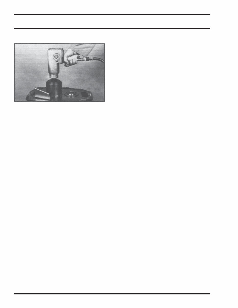
Tool Reference
This Spicer transmission can be repaired with ordinary
mechanic’s tools. However, if your transmission has a mainshaft
intermediate nut rather than a snap ring, vehicle downtime can
be minimized with the use of this special socket. It is available
through Sealed Power Corporation, part number OEM6599
To order, contact:
OTC Division
Sealed Power Corporation
O.E.M. Sales
655 Eisenhower Drive
Owatonna, MN 55060
Phone: (800) 533-6127
Fax: (800) 283-8665

Tech Support 1-800-401-9866
GENERAL
DISASSEMBLY
SECTION III
6
Important Procedure
To locate and correct unit power or auxiliary transmission
troubles, a systematic procedure should be followed.
Road test whenever possible. Mechanics usually get second-
or third-hand reports of trouble experienced with the unit. These
reports do not always accurately describe the actual
conditions. Sometimes symptoms seem to indicate trouble in
the transmission, while actually the problem is with the axle,
driveshaft, universal joints, engine or clutch. This is especially
true of noise complaints. Therefore, before removing the
transmission or related components to locate trouble, road
test to check the possibility of trouble in other closely associ-
ated units. Road testing is most effective when the mechanic
drives the vehicle. However, riding with the driver can be very
informative.
Check Functioning
Prior to Disassembly
If a remote control is used, a careful check of the remote and
connecting linkages (and their adjustment) must be made. The
remote unit must be in good working order if the transmis-
sion is expected to shift satisfactorily.
Many times, the answer to the trouble is apparent when the unit
is inspected prior to disassembly. But this evidence is often lost
when the parts are separated. If possible, check the
unit prior to disassembly. Bear in mind that a careful inspection
of the unit should be made as each disassembly step is
performed.
Inspect Thoroughly
During Disassembly
It is poor practice to disassemble a unit or the complete
transmission as quickly as possible without examining the
parts. The mechanic may completely dissemble a unit and fail
to find the cause of the trouble, unless he examines the parts.
After the transmission is disassembled, check the lubricant
for foreign particles, This is a source of trouble often overlooked
during the disassembly.
Repair or Replace Worn Parts
Many times the parts or critical adjustments causing the trouble
are not replace or corrected because the mechanic only
inspects and replaced parts that have failed completely. All
pieces should be carefully examined because broken parts
are often just the result—not the cause—of the problem. All
parts that are broken or worn and no longer meet specifications
should be replaced.
Also, parts that are worn to the extent that they do not have a
long service life remaining should be replace. Replacing
these parts now will avoid another teardown on the unit in the
near future. Also at this time, make the recommended changes
or modifications to bring the transmission up to date and
increase the service life of the unit.
Tech Support 1-800-401-9866
GENERAL
DISASSEMBLY
SECTION III
7
Read this section before starting the
detailed disassembly proce-dures.
Follow each procedure closely in
each section, making use of both text and
pictures.
Rebuild Facilities
A suitable holding fixture or overhaul stand with a hole for the
input shaft is desirable.
For easier working conditions, table height should be 28 - 30
inches. A light chain hoist should be used to handle the
mainshaft and countershaft during removal and reassembly
procedures.
Cleanliness
Transmissions should be steam cleaned prior to disassembly.
Seal all openings before steam cleaning to prevent entry of dirt
and water which can damage serviceable parts.
Dirt is abrasive and will cause premature wear of bearings and
other parts. TTC suggests that mechanics have a wash tank
available to clean parts just prior to reassembly.
Bearings
When a transmission is removed at relatively low mileage,
bearings should be removed with pullers designed for this
purpose. Wrap the bearings to keep out dirt. Clean, inspect,
and lubricate all bearings just prior to reassembly. If accumu-
lated mileage is over 150,000 miles, we suggest that all
bearings be replaced. If bearings are worn or damaged,
always replace them regardless of mileage.
!
End Yokes and Flanges
Do not hammer on end yokes and flanges to
remove or install them. It is not only destructive to
the yoke or the flange itself, but can also cause
serious internal damage. Hammering destroys or
mutilates the pilot diameters and warps or bends the flange.
Hammering on end yokes will close-in the bearing bores or
misalign yoke lugs. This will result in early failures of journal
needle bearings.
Serious damage can be done internally to bearings, thrust
faces and washers, pilot bearings, etc., by hammering on
external parts. In most designs, when the yoke/flange locknuts
are tightened and secure, the internal bearings and gears are
in proper location. When the yoke/flange is driven on the shaft,
however, two conditions can exist.
(a) If the bearing fit is tight on the shaft, usually the bear-
ings will brinell as they must absorb the pounding force.
(b) If the bearing fit is loose, the shaft will keep moving
inward until it is stopped by the internal parts such as
the pilot bearing thrust washers.
Power Take-Offs
Refer to your owner’s manual and installation procedures
when installing any PTO on your transmission.
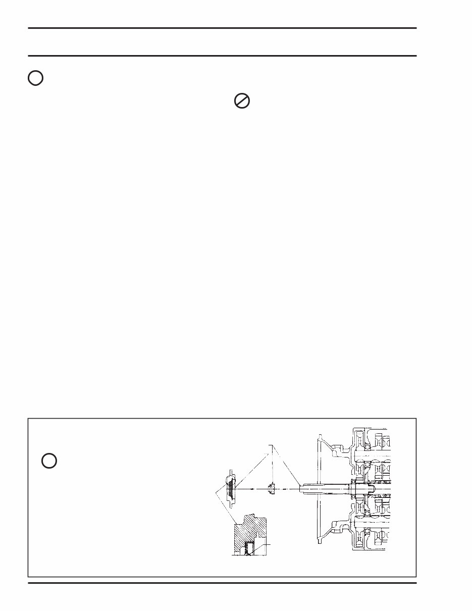
Front Bearing Retainer & Seal
When installing the front bearing
retainer and seal in the transmis-
sion, use the red plastic sleeve to
prevent serious damage to the oil
seal. Failure to use the seal sleeve
will void the seal warranty.
!
PUSH SLEEVE OVER END OF SHAFT
INSTALL BEARING CAP ASSEMBLY
AFTER RED SLEEVE IS IN PLACE
INSTALL SEAL DRY
HYDRODYNAMIC LIP
SEAL MUST BE INSTALLED SO THAT HYDRODYNAMIC
LIP FACES TOWARD INSIDE OF TRANSMISSION
REMOVE SEAL CARDBOARD SHIPPING TUBE OR
PLASTIC INSTALLATION SLEEVE JUST PRIOR TO
INSTALLING BEARING CAP ASSEMBLY TO
TRANSMISSION
Tech Support 1-800-401-9866
SHIFT TOWER
DISASSEMBLY
SECTION IV
8
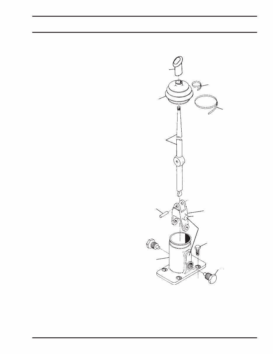
Shift Tower Disassembly
1. Begin disassembly by cutting the two tie cables which
secure the boot.
2. Slide the boot off the shift lever.
3. Remove the two trunnion screws.
4. Lift the lever from the tower.
5. To remove the shift yoke from the lever, simply press out
the pivot pin.
6. Wash all parts. Inspect them thoroughly for damage.
Replace parts as necessary.
HANDLE
UPPER TIE CABLE
BOOT
LOWER TIE CABLE
SHIFT LEVER
PIVOT PIN
YOKE
BOSS
SHIFT TOWER SCREW
SHIFT TOWER
TRUNNION SCREW
You're Reading a Preview
What's Included?
Fast Download Speeds
Online & Offline Access
Access PDF Contents & Bookmarks
Full Search Facility
Print one or all pages of your manual
$32.99
Viewed 99 Times Today


Secure transaction
What's Included?
Fast Download Speeds
Online & Offline Access
Access PDF Contents & Bookmarks
Full Search Facility
Print one or all pages of your manual
$32.99
The International ES52-7B, ES56-7B, and ES066-7B 7-speed transmission repair manual provides comprehensive guidance for the complete teardown and rebuild of these transmissions. Whether you are a professional mechanic or a DIY enthusiast, this manual equips you with the technical information needed to effectively repair and maintain these transmissions.


