

DANA SPICER TE27 & TE32 Transmission Service Repair Manual
What's Included?
Fast Download Speeds
Online & Offline Access
Access PDF Contents & Bookmarks
Full Search Facility
Print one or all pages of your manual

SPICER OFF-HIGHWAY PRODUCTS DIVISION
Maintenance and Service manual
TE27 / 32
POWERSHIFT TRANSMISSION
Manual: 8100102
CD-ROM: 8100101
4 SPEED
SHORT DROP

TE27/32 4 SD 12/2002
Table of Contents
TOWING OR PUSHING
FOREWORD
1 SAFETY PRECAUTIONS .................................................................................................... 1
2 CLEANING AND INSPECTION ........................................................................................... 1
2.1 CLEANING ...................................................................................................................................... 2
2.1.1 BEARINGS ............................................................................................................................ 2
2.1.2 HOUSINGS ............................................................................................................................ 2
2.2 INSPECTION .................................................................................................................................... 2
2.2.1 BEARINGS ............................................................................................................................ 2
2.2.2 OIL SEALS, GASKETS, etc. ................................................................................................. 3
2.2.3 GEARS & SHAFTS................................................................................................................ 3
2.2.4 HOUSINGS, COVERS, etc. ................................................................................................... 3
2.3 LEGEND SYMBOLS ........................................................................................................................ 3
3 TECHNICAL SPECIFICATIONS .......................................................................................... 1
3.1. IDENTIFICATION OF THE UNIT ...................................................................................................... 2
3.2. WEIGHT, DIMENSIONS, OIL CAPACITY......................................................................................... 2
3.3 TIGHTENING TORQUES.................................................................................................................. 3
3.4 PRESSURE & TEMPERATURE SPECIFICATIONS ........................................................................ 5
3.5 ELECTRICAL SPECIFICATIONS .................................................................................................... 6
3.6 HYDRAULIC COOLER LINES SPECIFICATIONS .......................................................................... 6
4 MAINTENANCE ............................................................................................................... 1
4.1. OIL SPECIFICATION........................................................................................................................ 2
4.1.1 RECOMMENDED LUBRICANTS .......................................................................................... 2
4.2 MAINTENANCE INTERVALS........................................................................................................... 2
4.2.1 DAILY ..................................................................................................................................... 2
4.2.2 NORMAL DRAIN PERIOD ..................................................................................................... 2
4.3 SERVICING MACHINE AFTER COMPONENTS OVERHAUL ......................................................... 3
5 INSTALLATION DETAILS .................................................................................................... 1
5.1 CONVERTER DRIVE COUPLING ................................................................................................. 2
5.2 TRANSMISSION TO ENGINE INSTALLATION PROCEDURE........................................................ 3
5.3 EXTERNAL PLUMBING................................................................................................................... 4
5.3.1 COOLER & FILTER LINES SPECIFICATIONS ...................................................................... 4
5.4 SPEED SENSOR INSTALLATION ................................................................................................... 5

TE27/32 4 SD 12/2002
6 TRANSMISSION OPERATION ............................................................................................ 1
6.1 THE TRANSMISSION ASSEMBLY .................................................................................................. 2
6.1.1 THE CONVERTER, PUMP DRIVE SECTION AND PRESSURE REGULATING VALVE ...... 3
6.1.2 THE INPUT SHAFT AND DIRECTIONAL CLUTCHES ........................................................ 4
6.1.3 THE RANGE CLUTCHES ..................................................................................................... 5
6.1.4 THE OUTPUT SECTION ....................................................................................................... 5
6.2 THE TRANSMISSION CONTROLS (REFER TO HYDRAULIC DIAGRAM) .................................... 6
6.3 ELECTRIC SOLENOID CONTROLS ............................................................................................... 6
6.4 POWERFLOWS, ACTIVATED SOLENOIDS AND HYDRAULIC CIRCUIT...................................... 7
6.4.1 NEUTRAL SELECTED........................................................................................................... 7
6.4.2 FORWARD 1ST SPEED ........................................................................................................ 9
6.4.3 FORWARD 2ND SPEED...................................................................................................... 11
6.4.4 FORWARD 3RD SPEED...................................................................................................... 13
6.4.5 FORWARD 4TH SPEED ...................................................................................................... 15
6.4.6 REVERSE 1ST SPEED ....................................................................................................... 17
6.4.7 REVERSE 2ND SPEED ....................................................................................................... 19
6.4.8 REVERSE 3RD SPEED ....................................................................................................... 21
6.4.9 REVERSE 4TH SPEED ....................................................................................................... 23
6.5 GEAR AND CLUTCH LAYOUT ....................................................................................................... 25
7 TROUBLESHOOTING GUIDE ............................................................................................. 1
7.1 THE TRANSMISSION....................................................................................................................... 2
7.2 THE INPUT SHAFT AND DIRECTIONAL CLUTCHES .................................................................... 2
7.2.1 STALL TEST .......................................................................................................................... 2
7.2.2 TRANSMISSION PRESSURE CHECK ................................................................................. 3
7.2.3 MECHANICAL AND ELECTRICAL CHECKS ........................................................................ 3
7.2.4 HYDRAULIC CHECKS ........................................................................................................... 3
7.3 TROUBLESHOOTING GUIDE......................................................................................................... 4
7.3.1 LOW CLUTCH PRESSURE................................................................................................... 4
7.3.2 LOW CHARGING PUMP OUTPUT FLOW ............................................................................ 4
7.3.3 OVERHEATING...................................................................................................................... 4
7.3.4 NOISE CONVERTER............................................................................................................. 4
7.3.5 LACK OF POWER ................................................................................................................. 4
7.4 CHECK POINTS ............................................................................................................................... 5
7.5 SPEED SENSOR - STATIC STANDALONE TEST ........................................................................... 8
8 SECTIONAL VIEWS & PARTS IDENTIFICATION............................................................... 1
TE 27/32 TORQUE CONVERTER GROUP................................................................................................. 2
TE 27/32 TORQUE CONVERTER GROUP................................................................................................. 3
TE 27/32 TRANSMISSION CASE & REAR COVER GROUP .................................................................... 4
TE 27/32 TRANSMISSION CASE & REAR COVER GROUP .................................................................... 5
TE 27/32 TURBINE SHAFT GROUP .......................................................................................................... 6
TE 27/32 TURBINE SHAFT GROUP .......................................................................................................... 7
TE 27/32 PUMP DRIVE GROUP................................................................................................................. 8
TE 27/32 PUMP DRIVE GROUP................................................................................................................. 9
TE 27/32 ADAPTOR SLEEVE GROUP .................................................................................................... 10
TE 27/32 ADAPTOR SLEEVE GROUP .................................................................................................... 11
TE 27/32 WHEEL GROUP ........................................................................................................................ 12
TE 27/32 WHEEL GROUP ........................................................................................................................ 13

TE27/32 4 SD 12/2002
TE 27/32 DRIVE PLATE GROUP ............................................................................................................. 14
TE 27/32 DRIVE PLATE GROUP ............................................................................................................. 15
TE 27/32 FWD & REV/2ND AND 3TH OR 4TH CLUTCH SHAFT ASSY ................................................ 16
TE 27/32 FWD & REV/2ND AND 3TH OR 4TH CLUTCH SHAFT ASSY ................................................ 17
TE 27/32 forward clutch shaft GROUP ................................................................................................... 18
TE 27/32 forward clutch shaft GROUP ................................................................................................... 19
TE 27/32 3rd speed clucth shaft GROUP ............................................................................................... 20
TE 27/32 3rd speed clucth shaft GROUP ............................................................................................... 21
TE 27/32 3rd speed gear.......................................................................................................................... 22
TE 27/32 3rd speed gear.......................................................................................................................... 23
TE 27/32 REV / 2nd schaft GROUP......................................................................................................... 24
TE 27/32 REV / 2nd schaft GROUP......................................................................................................... 25
TE 27/32 1st speed clutch shaft GROUP ............................................................................................... 26
TE 27/32 1st speed clutch shaft GROUP ............................................................................................... 27
TE 27/32 4th speed clutch shaft GROUP ............................................................................................... 28
TE 27/32 4th speed clutch shaft GROUP ............................................................................................... 29
TE 27/32 1st shaft gear GROUP.............................................................................................................. 30
TE 27/32 1st shaft gear GROUP.............................................................................................................. 31
TE 27/32 Output shaft GROUP................................................................................................................ 32
TE 27/32 output shaft group ................................................................................................................... 33
TE 27/32 Regulator valve group ............................................................................................................. 34
TE 27/32 Regulator valve group ............................................................................................................. 35
TE 27/32 control valve GROUP ............................................................................................................... 36
TE 27/32 control valve GROUP ............................................................................................................... 37
TE 27/32 control valve GROUP (cont.) ................................................................................................... 38
TE 27/32 control valve GROUP (cont.) ................................................................................................... 39
TE 27/32 remote filter adapter GROUP .................................................................................................. 40
TE 27/32 remote filter adaptor GROUP .................................................................................................. 41
9 ASSEMBLY INSTRUCTIONS .............................................................................................. 1
10 DISASSEMBLY AND REASSEMBLY OF THE TRANSMISSION...................................... 1
11 SPECIAL TOOLS ............................................................................................................... 1

TE27/32-4-SD 12/02 I
TOWING OR PUSHING
Before towing the vehicle, be sure to lift the rear wheels off the ground or disconnect the driveline to avoid dam-
age to the transmission during towing.
NOTE:
Because of the design of the hydraulic system, the engine cannot be started by pushing or towing.
©Copyright Dana Spicer Off-Higwhay Products Division
Unpublished Material - All rights reserved
Limited Distribution
No part of this work may be reproduced in any form under any means without direct written permission of the
Dana Spicer Off-Highway Products Division

TE27/32-4-SD 12/02 II
FOREWORD
This manual has been prepared to provide the customer and the maintenance personnel with information and
instructions on the maintenance and repair of the SPICER OFF-HIGWAY PRODUCTS product.
Extreme care has been exercised in the design, selection of materials, and manufacturing of these units. The
slight outlay in personal attention and cost required to provide regular and proper lubrication, inspection at stated
intervals, and such adjustments as may be indicated, will be reimbursed many times in low cost operation and
trouble-free service.
In order to become familiar with the various parts of the product, its principle of operation, troubleshooting and
adjustments, it is urged that the mechanic studies the instructions in this manual carefully and uses it as a refer-
ence when performing maintenance and repair operations.
Whenever repair or replacement of component parts is required, only SPICER OFF-HIGHWAY PRODUCTS ap-
proved parts as listed in the applicable parts manual should be used. Use of “will-fit” or non-approved parts may
endanger proper operation and performance of the equipment. SPICER OFF-HIGHWAY PRODUCTS does not
warrant repair or replacement parts, nor failures resulting from the use of parts which are not supplied or ap-
proved by SPICER OFF-HIGHWAY PRODUCTS.
IMPORTANT
ALWAYS FURNISH THE DISTRIBUTOR WITH THE SERIAL AND MODEL NUMBER WHEN ORDERING PARTS.

TE27/32-4-SD 12/02 III
FWD
2ND
3RD
1ST REV
4TH

TE27/32-4-SD 12/02 1-1
1. SAFETY PRECAUTIONS
To reduce the chance of personal injury and/or property damage, the following instructions must be carefully
observed.
Proper service and repair are important to the safety of the service technician and the safe reliable operation of
the machine. If replacement parts are required the part must be replaced by a spare part which has the same
part number or with an equivalent part. DO NOT USE A SPARE PART OF LESSER QUALITY.
The service procedures recommended in this manual are effective methods for performing service and
repair. Some of these procedures require the use of tools specifically designed for the purpose.
Accordingly, anyone who intends to use a spare parts, service procedure or tool, which is not recommended by
SPICER OFF-HIGHWAY PRODUCTS, must first determine that neither his safety nor the safe operation of the
machine will be jeopardized by the spare part, service procedure or tool selected.
IMPORTANT
It is important to note that this manual contains various ’CAUTIONS’ and ‘NOTES’ that must be carefully observed in
order to reduce the risk of personal injury during service or repair, or the possibility that improper service or repair
may damage the unit or render it unsafe.
It is also important to understand that these ‘CAUTIONS” and ‘NOTES’ are not exhaustive, because it is impossible
to warn about all the possible hazardous consequences that might result from failure to follow these instructions.

TE27/32-4-SD 12/02 2-1
2. CLEANING, INSPECTION AND LEGEND SYMBOLS
2.1 CLEANING
Clean all parts thoroughly using solvent type cleaning fluid. It is recommended that parts be immersed in
cleaning fluid and moved up and down slowly until all old lubricant and foreign material is dissolved and parts are
thoroughly cleaned.
CAUTION
Care should be exercised to avoid skin rashes, fire hazards, and inhalation of vapors when using solvent type clean-
ers.
2.1.1 Bearings
Remove bearings from cleaning fluid and strike flat against a block of wood to dislodge solidified particles
of lubricant. Immerse again in cleaning fluid to flush out particles. Repeat above operation until bearings are
thoroughly clean. Dry bearings using moisture-free compressed air. Be careful to direct air stream across bearing
to avoid spinning. Do not spin bearings when drying. Bearings may be rotated slowly by hand to facilitate drying
process.
2.1.2 Housings
Clean interior and exterior of housings, bearing caps, etc…, thoroughly. Cast parts may be cleaned in hot solution
tanks with mild alkali solutions providing these parts do not have ground or polished surfaces.
Parts should remain in solution long enough to be thoroughly cleaned and heated. This will aid the evaporation of
the cleaning solution and rinse water. Parts cleaned in solution tanks must be thoroughly rinsed with clean water
to remove all traces of alkali. Cast parts may also be cleaned with steam cleaner.
CAUTION
Care should be exercised to avoid inhalation of vapors and skin rashes when using alkali cleaners.
All parts cleaned must be thoroughly dried immediately by using moisture-free compressed air or soft, lintless
absorbent wiping rags free of abrasive materials such as metal fillings, contaminated oil, or lapping compound.
2.2 INSPECTION
The importance of careful and thorough inspection of all parts cannot be overstressed. Replacement of all parts
showing indication of wear or stress will eliminate costly and avoidable failures at a later date.
2.2.1 Bearings
Carefully inspect all rollers: cages and cups for wear, chipping, or nicks to determine fitness of bearings for
further use. Do not replace a bearing cone or cup individually without replacing the mating cup or cone at the
same time. After inspection, dip bearings in Automatic Transmission Fluid and wrap in clean lintless cloth or
paper to protect them until installed.
TE27/32-4-SD 12/02 2-2
2.2.2 Oil Seals, Gaskets, Etc.
Replacement of spring load oil seals, “O” rings, metal sealing rings, gaskets, and snap rings is more economical
when unit is disassembled than premature overhaul to replace these parts at a future time.
Further loss of lubricant through a worn seal may result in failure of other more expensive parts of the assembly.
Sealing members should be handled carefully, particularly when being installed. Cutting, scratching, or curling
under of lip of seal seriously impairs its efficiency. When assembling new metal type sealing rings, these should
be lubricated with coat of chassis grease to stabilize rings in their grooves for ease of assembly of mating
members. Lubricate all “O” rings and seals with recommended type Automatic Transmission Fluid before
assembly.
2.2.3 Gears and Shafts
If magna-flux process is available, use process to check parts. Examine teeth on all gears carefully for wear,
pitting, chipping, nicks, cracks, or scores. If gear teeth show spots where case hardening is worn through or
cracked, replace with new gear. Small nicks may be removed with suitable hone. Inspect shafts and quills to
make certain they are not sprung, bent, or splines twisted, and that shafts are true.
2.2.4 Housing, Covers, etc.
Inspect housings, covers and bearing caps to ensure that they are thoroughly clean and that mating surfaces,
bearing bores, etc…, are free from nicks or burrs. Check all parts carefully for evidence of cracks or conditions
which would cause subsequent oil leaks or failures.
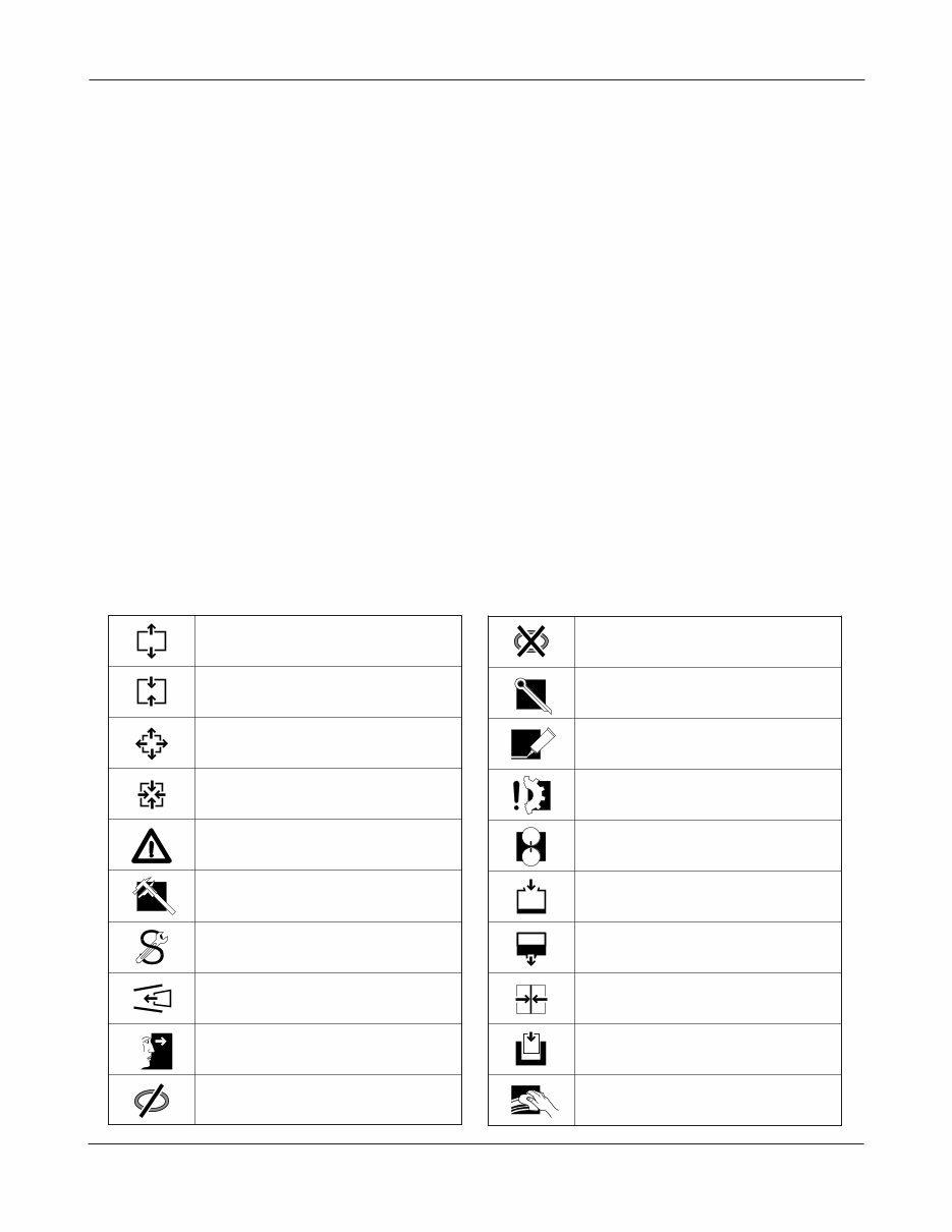
2.3 LEGEND SYMBOLS
Cleaning, inspection and legend symbols
Smontaggio di sottogruppi
Montaggio di sottogruppi
Smontaggio di particollari ingombranti
Montaggio di particollari ingombranti
Attenzione, indicazione importante
Controllare regolare p.e. coppie, misure, pressione etc.
T = Attrezzature speciali P = Pagina
Rispettare direzione di montaggio
Controllare esaminare controllo visuale
Eventualimente riutilizzable (sostituire se necessario)
Sostituire con ogni montaggio
Togliere - mettere la sicura
Mettere la sicura, incollare (mastice liquido)
Evitare danni ai materiali, danni ai pezzi
Marchiari prima dello smontaggio (per il montaggio)
Carricare riempire (olio - lubrificante)
Scarricare olio, lubrificante
Tendere
Insere pressione nel circuito idraulico
Pulire
Disassembly of assembly groups
Reassemble to from assembly group
Remove obstruction parts
Reinstall - remount parts which had obstructed disassembly
Attention! important notice
Check - adjust e.g. torque, dimensions, pressures etc.
T = Special tool P = Page
Note direction of installation
Visual inspection
Possibly still serviceable, renew if necessary
Renew at each reassembly
Unlock - lock e.g. split pin, locking plate, etc.
Lock - adhere (liquid sealant)
Guard against material damage, damage to parts
Mark before disassembly, observe marks when reasembl.
Filling - topping up - refilling e.g. oil, cooling water, etc.
Drain off oil, lubricant
Tighten - clamp ; tightening a clamping device
Apply pressure into hydraulic circuit
To clean
You're Reading a Preview
What's Included?
Fast Download Speeds
Online & Offline Access
Access PDF Contents & Bookmarks
Full Search Facility
Print one or all pages of your manual
$30.99
Viewed 61 Times Today


Secure transaction
What's Included?
Fast Download Speeds
Online & Offline Access
Access PDF Contents & Bookmarks
Full Search Facility
Print one or all pages of your manual
$30.99
Dive into the comprehensive DANA SPICER TE27 & TE32 Transmission Service Repair Manual, spanning 121 pages. This Maintenance & Service Manual covers the TE27 / TE32 Powershift Transmission, featuring a 4-speed configuration with a short drop. Whether you're a professional mechanic or a DIY enthusiast, this manual equips you with the essential knowledge to effectively service and repair these transmissions.


