

ISUZU AW03-72LE Automatic Transmission AUTO Gearbox Manual
What's Included?
Fast Download Speeds
Online & Offline Access
Access PDF Contents & Bookmarks
Full Search Facility
Print one or all pages of your manual
FOR SERVICE TRAINING
AUTOMATIC TRANSMISSION
(AW03-72LE)
ISUZU MOTORS LIMITED
AW03-72LE Automatic Transmission-1
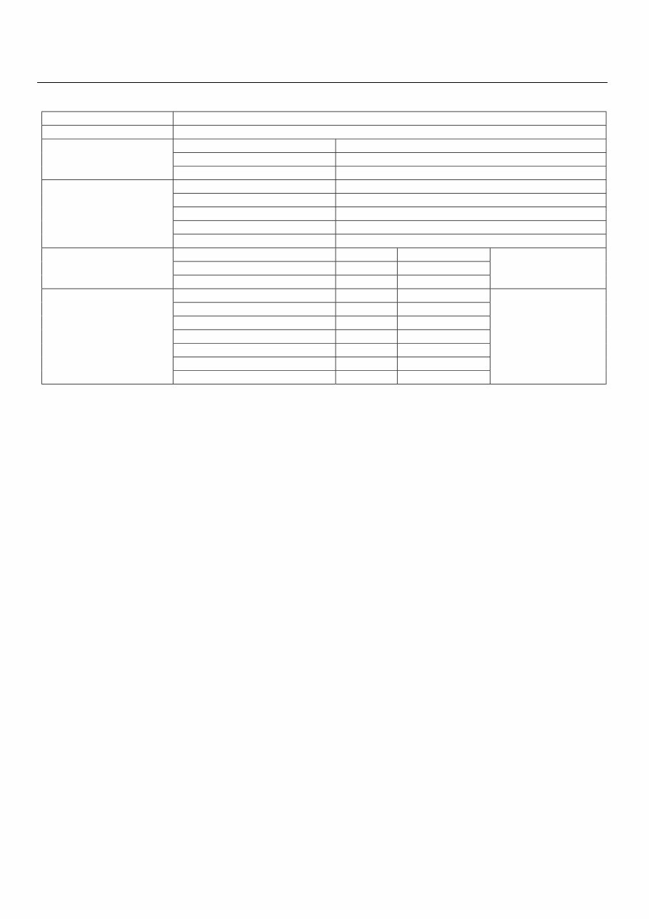
MAIN DATA & SPECIFICATION
Model AW03-72LE
Torque Converter Type Three Elements, One Stage & Two Phase Type with Lock-up Function
Name ATF DEXRON II or III
Quantity Approximately 6.5L
ATF
Cooling System Water Cooled Type (Radiator)
1
st
2.826
2
nd
1.493
3
rd
1.000
4
th
(Over Drive) 0.688
Gear Ratio
Reverse 2.703
One-way Clutch No. 1 F-1 18
One-way Clutch No. 2 F-2 26
Clutch
Over Drive One-way Clutch F-0 20
Number of Sprag
Forward Clutch C-1 4
Direct Clutch C-2 3
Over Drive Direct Clutch C-0 2
Second Coast Brake B-1 2
Second Brake B-2 3
First & Reverse Brake B-3 5
Friction Element
Over Drive Brake B-0 3
Number of Disc
AW03-72LE Automatic Transmission-2
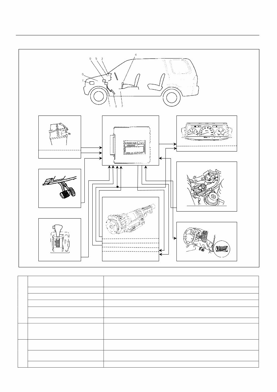
SYSTEM DIAGRAM
Vehicle Speed Sensor (SP1) Detects output shaft revolution seed and send signal to TCM and
speedometer.
Vehicle Speed Sensor (SP2) Detects output shaft revolution seed and send signal to TCM.
Throttle Position Sensor Detects injection pump lever operating angle and send signal to TCM.
Inhibitor Switch Detects select lever position and send signal to TCM.
Over Drive Switch Detects overdrive request switch selected by driver and send signal to
TCM.
Input
Brake Switch Detects brake pedal operated by driver and send signal to TCM.
TCM Judges necessary line pressure, gear shifting point and lock-up operation
based on electrical signals from switches and sensors and send
appropriate signals to solenoids.
Shift Solenoid (S1 & S2) Selects appropriate gear shifting position for current driving condition
based on signal from TCM.
Lock-up Solenoid (S3) Regulates lock-up pressure for current driving condition based on signal
from TCM.
Output
CHECK TRANS Indicator Lamp Indicates CHECK TRANS indicator lamp in case of malfunction.
8. Brake Pedal
-Brake Switch
3. 5. Meter
-CHECK TRANS Indicator Lamp
-Speedometer
1. Transmission Control Module
(TCM)
4. Select Lever
-Over Drive Switch
9. Data Link Connector (DLC)
6. Engine
-Throttle Position Sensor
2. Transmission
-Inhibitor Switch
-Vehicle Speed Sensor (SP1)
-Vehicle Speed Sensor (SP2)
-Shift Solenoid (S1 & S2)
-Lock-up Solenoid (S3)
7. Electrical Source
-Ignition Voltage
-Battery
AW03-72LE Automatic Transmission-3
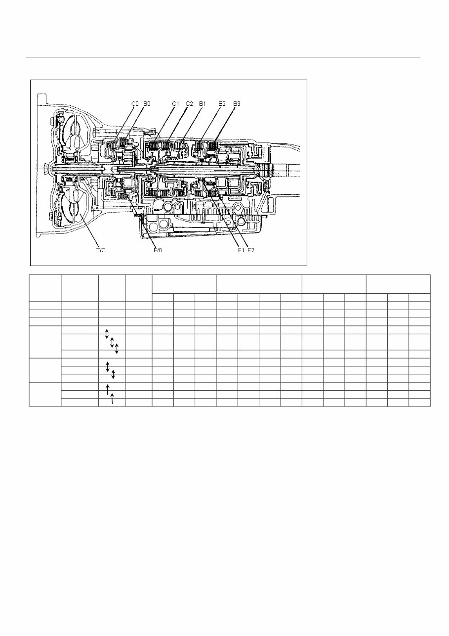
LOCATION & OPERATION OF CLIUTCH, BRAKE, ONE-WAY CLUTCH AND SOLENOID
C0: Over Drive Direct Clutch
C1: Forward Clutch
C2: Direct Clutch
B0: Over Drive Brake
B1: Second Coast Brake
B2: Second Brake
B3: First & Reverse Brake
F0: Over Drive One-way Clutch
F1: One-way Clutch (No. 1)
F2: One-way Clutch (No. 2)
Clutch Brake One-way Clutch Solenoid Select
Lever
Position
Gear
Position
Gear
Shift
Lock-
up
C-0 C-1 C-2 B-0 B-1 B-2 B-3 F-0 F-1 F-2 S1 S2 S3
P - O O
R - O O O O O
N - O O
1
st
O O O O O
2
nd
O O O O O O O
3
rd
O O O O O O O O
D
4
th
(O/D) O O O O O O
1
st
O O O O O
2
nd
O O O O O O O O
2
3
rd
O O O O O O
1
st
O O O O O O
2
nd
O O O O O O O O
L
3
rd
O O O O O O

AW03-72LE Automatic Transmission-4
CONTENTS OF FUNCTION & CONTROL
Item Description
Gear Shift Control The TCM issues a shift solenoid drive signal based on the inhibitor switch, vehicle
speed and throttle opening. And, the TCM control shift schedule according to the
preset shift map.
In order to prevent engine over running, the TCM achieves up shift control 3
rd
to 4
th
when the vehicle speed is more than 110km/h even over drive (O/D) is tuned off. It
will return 4
th
to 3
rd
when the vehicle speed is less than 100km/h.
Lock-up Control The lock-up solenoid adjusts the pressure based on the signal from the TCM
according to the vehicle speed, throttle opening, select lever position based on the
preset lock-up point to control the lock-up.
The lock-up is disengaged when the throttle is closed or brake pedal is depressed.
Squat Control At garage shift, shift to the 1
st
gear sequentially after shifting into the 3
rd
gear first to
improve the garage shift shock.
Fail-safe Function In case of malfunction of sensors, solenoid, TCM automatically begins fail-safe control
to minimize effects on driving.
Self-diagnosis Function Parts required for controlling the automatic transmission are provided with a self-
diagnosis function. When any trouble occurs, the CHECK TRANS indicator lamp
blinks to warm the driver. The trouble code is memorized into the TCM.
SHIFT SOLENOID FAIL-SAFE FUNCTION
Normal Solenoid S1 Malfunction Solenoid S2 Malfunction S1& S2 Malfunction Select
Lever
Position
S1 S2 Gear
Position
S1 S2 Gear
Position
S1 S2 Gear
Position
S1 S2 Gear
Position
O 1
st
X O 3
rd
O X 1
st
X X 4
th
(O/D)
O O 2
nd
X O 3
rd
X 4
th
(O/D) X X 4
th
(O/D)
O 3
rd
X O 3
rd
X 4
th
(O/D) X X 4
th
(O/D)
D
4
th
(O/D) X 4
th
(O/D) X 4
th
(O/D) X X 4
th
(O/D)
O 1
st
X O 3
rd
O X 1
st
X X 3
rd
O O 2
nd
X O 3
rd
X 3
rd
X X 3
rd
2
O 3
rd
X O 3
rd
X 3
rd
X X 3
rd
O 1
st
X 3
rd
O X 1
st
X X 3
rd
L
O O 2
nd
X 3
rd
O X 1
st
X X 3
rd
AW03-72LE Automatic Transmission-5
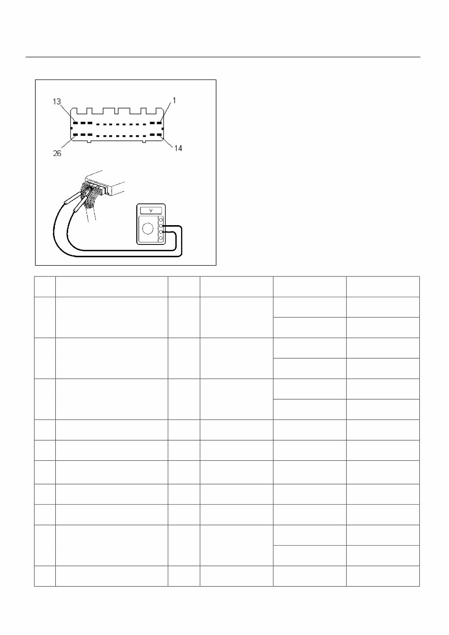
TCM PIN ASSIGNMENT
TCM voltage check is done to check for transmission
and TCM problems which cannot be detected by self-
diagnosis. Additionally, it severs as a back-up check
for self-diagnosis.
Measure the voltage drop and make a continuity test
for each of sensors, solenoids and switches. If the
voltage is within the specified range and continuity
exists, that particular area of the TCM and
transmission assembly is normal. If voltage deviation
or lack of continuity is discovered, disconnect the
applicable parts and check of them individually.
Pin Pin Name Input /
Output
Connected to Measurement
Condition
Standard
At L range 10 – 15 volts 1 L Range Switch Input Inhibitor Switch
Other than L range Less than 1 volt
At 2 Range 10 – 15 Volts 2 2 Range Switch Input Inhibitor Switch
Other than 2 range Less than 1 volt
At N Range 10 – 15 volts 3 N Range Switch Input Inhibitor Switch
Other than N range Less than 1 volt
4 Not Used - - - -
5 Not Used - - - -
6 Vehicle Speed Sensor (SP1) Input Vehicle Speed
Sensor (SP1)
At run in L range in
1
st
gear 20km/h
Pulse generated
(Approximately 5.6
volts by AC range)
7 Not Used - - - -
8 Throttle Position Sensor Ground - Throttle Position
Sensor
- Continuity with
ground
Switch depressed
(Over Drive ON)
10 – 15 volts 9 Over Drive Off Switch Input O/D Off Switch
Switch not depressed
(Over Drive OFF)
Less than 1 volt
10 Keyword 2000 Serial Data
Communication
Input /
Output
Data Link Connector
No. 7
- -

AW03-72LE Automatic Transmission-6
Pin Pin Name Input /
Output
Connected to Measurement
Condition
Standard
At lock-up 10 – 15 volts 11 Lock-up Solenoid Output Lock-up Solenoid
Other than lock-up Less than 1 volt
At 2
nd
, 3
rd
gear 10 – 15 volts 12 Shift Solenoid S2 Output Shift Solenoid S2
At 1
st
, 4
th
gear Less than 1 volt
At 1
st
, 2
nd
gear 10 – 15 volts 13 Shift Solenoid S1 Output Shift Solenoid S1
At 3
rd
, 4
th
gear Less than 1 volt
Pedal depressed 10 – 15 volts 14 Brake Switch Input Brake Switch
Pedal released Less than 1 volt
15 Not Used - - - -
16 Not Used - - - -
17 Not Used - - - -
Pedal released (Idle
position)
Approximately 0.45
volts
18 Throttle Position Sensor Signal Input Throttle Position
Sensor
Pedal fully depressed
(WOT)
Approximately 3.50
volts
Lamp turned ON Less than 1 volt 19 Check Trans Indicator Lamp Output CHECK TRANS
Indicator Lamp
Lamp turned OFF 10 – 15 volts
20 Throttle Position Sensor Voltage
Supply
Output Throttle Position
Sensor
Ignition switch ON Approximately 5 volts
21 Diagnosis Request Switch Input Data Link Connector
No. 11
- -
22 Vehicle Speed Sensor (SP2) High Input Vehicle Speed
Sensor (SP2)
At run in L range in
1
st
gear 20km/h
Pulse generated
(Approximately 0.48
by AC range)
23 Vehicle Speed Sensor (SP2) Low Input Vehicle Speed
Sensor (SP2)
Ignition switch OFF
and measure pins 22
and 23
Approximately 370
ohms
24 Ground - Body Ground - Continuity with
ground
25 Battery Voltage Supply Input Battery All time 10 – 15 volts
26 Ignition Voltage Supply Input Ignition Switch Ignition Switch ON 10 – 15 volts
AW03-72LE Automatic Transmission-7
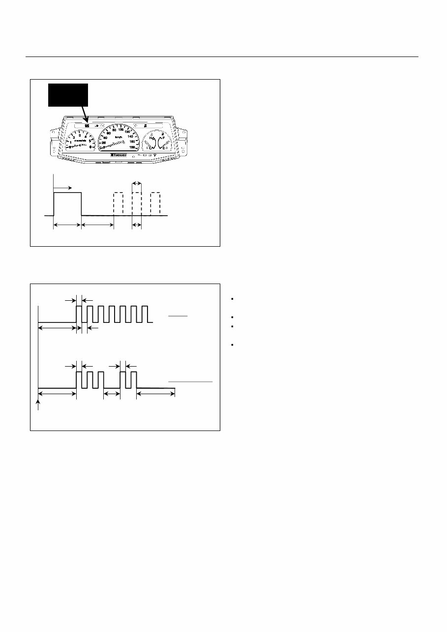
CHECK TRANS INDICATOR LAMP
"CHECK TRANS" is ON during 3 seconds at key
switch ON position. When trouble has occurred to
electrical components, "CHECK TRANS" lamp is
blinked (1.25 Hz) even during driving to warn the
driver. The trouble is recorded by trouble code in
TCM. When temporary trouble code has been
canceled, the "CHECK TRANS" lamp stops blinking.
This blinking can be stopped by setting the key off.
But the trouble code remains memorized in TCM.
SELF-DIAGNOSIS CODE (FLASH CODE) DISPLAY
Indication Method:
Terminal No. 11 and No. 4 or 5 (ground) of data
link connector are short circuited.
Turn the key switch to the ON position.
In case no trouble code existence, "CHECK
TRANS" lamp is blinked (1.25 Hz).
In case the plural trouble codes have occurred at
a time, each code are indicated three times in
numerical order.
Trouble Code Clear Method:
If you have Tech 2:
Follow the procedure instructed on the Tech 2.
Note:
If you clear the DTC you will not be able to read any
codes recorded during the last occurrence. To use
the DTC again to identify a problem, you will need to
reproduce the fault or the problem. This may require
a new test drive or just turning the key switch on (this
depends on the nature of the fault).
Key SW ON
OFF
ON
3 sec.
(Lamp Check)
Normal
Abnormal (DTC Stored)
3.2 sec.
0.4 sec.
0.4 sec.
CHECK
TRANS
Normal
Trouble Code (32)
Self-diagnosis Start
0.4Sec.
0.4Sec. 3.2Sec.
0.4Sec. 0.4Sec.
3.2Sec. 1.2Sec. 3.2Sec.
AW03-72LE Automatic Transmission-8
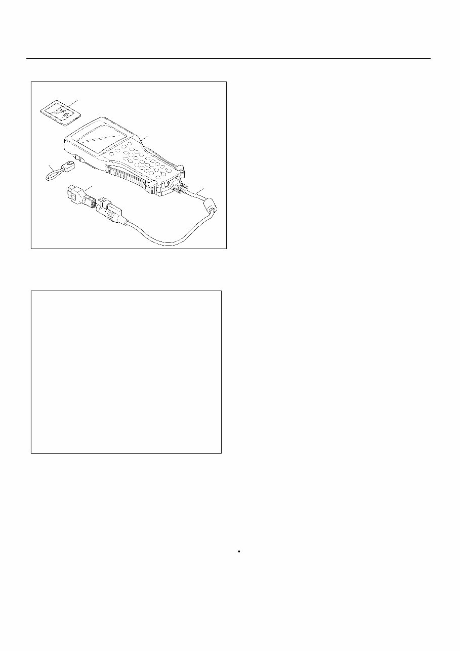
DIAGNOSIS WITH TECH 2
Getting Started
Before operating the Isuzu PCMCIA card with the
Tech 2, the following steps must be performed:
1. The PCMCIA card (1) inserts into the Tech 2 (5).
2. Connect the SAE 16/19 adapter (3) to the DLC
cable (4).
3. Connect the DLC cable to the Tech 2 (5).
4. Make sure the ignition switch is OFF.
5. Connect the Tech 2 SAE 16/19 (3) adapter to the
vehicle data link connector (DLC).
6. Turn the ignition ON and press the “PWR” key of
the Tech 2.
7. Verify the Tech 2 power up display.
Operating Procedure
1. Press Enter at start screen.
2. Select “F0 Diagnostic” then press Enter.
3. Select the appropriate vehicle identification.
4. Select “F0 Powertrain” then press Enter.
5. Select “AW03-72LE”.
The following table shows, which functions are used
the available equipment version.
F0: Diagnostic Trouble Codes
The purpose of the "Diagnostic Trouble Codes"
mode is to display stored trouble code in the TCM.
When "Clear DTC Information" is selected, a "Clear
DTC Information", warning screen appears. This
screen informs you that by cleaning DTC's "all stored
DTC information in the TCM will be erased".
F1: Data Display
The purpose of the "Data Display" mode is to
continuously monitor data parameters.
The current actual values of all important sensors
and signals in the system are display through F1
mode.
F2: Snapshot
"Snapshot" allows you to focus on making the
condition occur, rather than trying to view all of the
data in anticipation of the fault.
The snapshot will collect parameter information
around a trigger point that you select.
F3: Miscellaneous Test
The purpose of "Miscellaneous Test" mode is to
check for correct operation of electronic system
actuators.
Check Light Test
The purpose of this test is for checking whether
the CHECK TRANS indicator lamp is operated
when it commanded ON. Faulty circuit(s) or
opened bulb could be considered when not
operating with commanded ON.
F0: Diagnostic Trouble Codes
F0: Read DTC Info By Priority
F1: Read DTC Info As Stored By ECU
F2: Clear DTC Information
F1: Data Display
F2: Snapshot
F3: Miscellaneous Tests
F0: Lamps
F0: Check Light Test
F1: Solenoids
F0: Solenoid 2-3 Test
F1: Solenoid 1-2/3-4 Test
F2: TCC Solenoid Test
1
2
4 3
5

AW03-72LE Automatic Transmission-9
Solenoid 2-3 Test
The purpose of this test for checking whether the
shift solenoid S1 is operated when it commanded
ON/OFF. Faulty shift solenoid S1 could be
considered that does not create clicking noise
(solenoid operating noise), interrupted noise or
abnormal noise when commanded ON.
Solenoid 1-2/3-4 Test
The purpose of this test for checking whether the
shift solenoid S2 is operated when it commanded
ON/OFF. Faulty shift solenoid S2 could be
considered that does not create clicking noise
(solenoid operating noise), interrupted noise or
abnormal noise when commanded ON.
TCC Solenoid Test
The purpose of this test for checking whether the
lock-up solenoid S3 is operated when it
commanded ON/OFF. Faulty lock-up solenoid S3
could be considered that does not create clicking
noise (solenoid operating noise), interrupted noise
or abnormal noise when commanded ON.
You're Reading a Preview
What's Included?
Fast Download Speeds
Online & Offline Access
Access PDF Contents & Bookmarks
Full Search Facility
Print one or all pages of your manual
$41.99
$54.99
Viewed 82 Times Today


Secure transaction
What's Included?
Fast Download Speeds
Online & Offline Access
Access PDF Contents & Bookmarks
Full Search Facility
Print one or all pages of your manual
$41.99
$54.99
Our Isuzu AW03-72LE Automatic Transmission Auto Gearbox Manual is an essential resource for both professional mechanics and DIY enthusiasts. This comprehensive manual provides detailed technical information to assist in the repair and maintenance of the Isuzu AW03-72LE automatic transmission. Whether you're tackling a complete overhaul or a simple repair, this manual offers step-by-step instructions and diagrams to guide you through the process. With its clear and concise format, this manual is a valuable tool for anyone working on the Isuzu AW03-72LE automatic transmission.


