

Ford 4R100 4-Speed Automatic Transmission Service & Repair Manual
What's Included?
Fast Download Speeds
Online & Offline Access
Access PDF Contents & Bookmarks
Full Search Facility
Print one or all pages of your manual

INTRODUCTION
FORD 4R100
AUTOMATIC TRANSMISSION SERVICE GROUP
9200 S. DADELAND BLVD. SUITE 720
MIAMI, FLORIDA 33156
(305) 670-4161
DALE ENGLAND
FIELD SERVICE CONSULTANT
ED KRUSE
TECHNICAL CONSULTANT
WAYNE COLONNA
TECHNICAL SUPERVISOR
PETER LUBAN
TECHNICAL CONSULTANT
JIM DIAL
TECHNICAL CONSULTANT
GREGORY LIPNICK
TECHNICAL CONSULTANT
JERRY GOTT
TECHNICAL CONSULTANT
JON GLATSTEIN
TECHNICAL CONSULTANT
DAVID CHALKER
TECHNICAL CONSULTANT
STANTON ANDERSON
TECHNICAL CONSULTANT
ROLAND ALVAREZ
TECHNICAL CONSULTANT
MIKE SOUZA
TECHNICAL CONSULTANT
GERALD CAMPBELL
TECHNICAL CONSULTANT
1
No part of any ATSG publication may be reproduced, stored in any retrieval system or transmitted in any form or
by any means, including but not limited to electronic, mechanical, photocopying, recording or otherwise,
without written permission of Automatic Transmission Service Group. This includes all text illustrations,
tables and charts.
The information and part numbers contained in this booklet have
been carefully compiled from industry sources known for their
reliability, but ATSG does not guarantee its accuracy.
Copyright © ATSG 2003
Updated
October, 2003
The Ford 4R100 transmission is an updated version of the E4OD and was first introduced in the 1999 model
year, and is currently found in the F250, F350, F450 and F550 Super Duty trucks, E150, E250, E350, E450 vans
and the Expedition/Navigator/Excursion vehicles equipped with the 5.4L, 6.8L, and 7.3L engines. Some of the
4R100 units are equipped with a Power-Take-Off (PTO) window on the left hand side of the transmission case.
The revisions in the 4R100 have created many new engineering changes that have affected many of the internal
and external parts that will affect the servicing, repairing and overhaul of these units.
We wish to thank Ford Motor Company
for the information and illustrations
that have made this booklet possible.
INDEX
Copyright © ATSG 2003
FORD 4R100
2
AUTOMATIC TRANSMISSION SERVICE GROUP
9200 S. DADELAND BLVD. SUITE 720
MIAMI, FLORIDA 33156
(305) 670-4161
IDENTIFICATION TAG LOCATION AND INFORMATION ............................................................... 3
GENERAL DESCRIPTION AND OPERATION ..................................................................................... 4
COMPONENT AND SOLENOID APPLICATION CHART ................................................................... 5
"PTO" GENERAL REQUIREMENTS .................................................................................................... 6
ELECTRICAL COMPONENT DIAGNOSIS ........................................................................................... 8
FLUID REQUIREMENTS ....................................................................................................................... 12
SOLENOID PACK TESTING .................................................................................................................. 12
ABBREVIATION DESCRIPTION .......................................................................................................... 14
DIAGNOSTIC TROUBLE CODE CHART AND DESCRIPTION ........................................................ 15
LINE PRESSURE TEST .......................................................................................................................... 21
NON-PTO AND PTO HYDRAULIC DIFFERENCES ........................................................................... 22
PWM AND NON-PWM OIL PUMPDIFFERENCES ........................................................................... 34
CASE CHECKBALL LOCATIONS ......................................................................................................... 38
VALVE BODY CHECKBALL LOCATIONS ........................................................................................... 39
AIR PRESSURE CHECKS ...................................................................................................................... 40
TRANSMISSION DISASSEMBLY ......................................................................................................... 41
COMPONENT REBUILD SECTION
TRANSMISSION CASE ASSEMBLY ................................................................................................ 55
FRONT AND REAR PLANETARYCARRIERS ............................................................................... 64
FORWARD CLUTCH HOUSING ...................................................................................................... 66
DIRECT CLUTCH HOUSING ........................................................................................................... 69
FORWARD, DIRECT, SUN SHELL SUB-ASSEMBLY .................................................................... 76
CENTER SUPPORT ASSEMBLY ...................................................................................................... 80
INTERMEDIATE/OVERDRIVE CYLINDER ASSEMBLY ............................................................. 82
OVERDRIVE GEARSET ASSEMBLY ............................................................................................... 84
COAST CLUTCH HOUSING DIFFERENCES ................................................................................ 88
COAST CLUTCH HOUSING ASSEMBLY ........................................................................................ 90
OIL PUMP ASSEMBLY ...................................................................................................................... 94
VALVE BODY ASSEMBLY ............................................................................................................... 100
TRANSMISSION FINAL ASSEMBLY ................................................................................................. 102
MANUAL VALVE CHECK .................................................................................................................... 111
MANUAL SHIFT LEVER DIFFERENCES ........................................................................................ 112
TORQUE SPECIFICATIONS ............................................................................................................... 115
VALVE BODY BOLT CHART AND IDENTIFICATION .................................................................... 116
BOLT CHART AND IDENTIFICATION ............................................................................................. 117
SPECIAL SERVICE TOOLS ................................................................................................................. 118
3
AUTOMATIC TRANSMISSION SERVICE GROUP
Technical Service Information
Copyright © 2003 ATSG
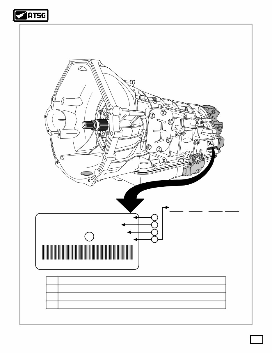
RFF81P-7006-BA
Ford
Ford Ford
98
XW4P-AC
RJL-B
004361
BD-9C17
17 C 9 BD-
Build
Date
Year Month Day
9=1999
0=2000
1=2001
2=2002
3=2003
A=Jan
B=Feb
C=Mar
D=Apr
E=May
F=Jun
G=Jul
H=Aug
J=Sep
K=Oct
L=Nov
M=Dec
XW4P-AC
5G
RJL-B
BD-9C17
004361
004361 6520
4 X 4 4 X 4
1
2
3
4
Build Date (Year, Month, Day)
Serial Number
Transmission Model
Assembly Part Number, Prefix And Suffix 1
2
3
4
TRANSMISSION IDENTIFICATION
WITH POWER TAKE OFF OPTION
PTO is available as an option on 8500 GVW or above, Super Duty
F-Series trucks with 6.8L gasoline and 7.3L Diesel engines.
Ford 4R100 transmissions on other models are not PTO capable.
Note:
Figure 1
AUTOMATIC TRANSMISSION SERVICE GROUP
Technical Service Information
4
Copyright © 2003 ATSG
TRANSMISSION
DESCRIPTION AND OPERATION
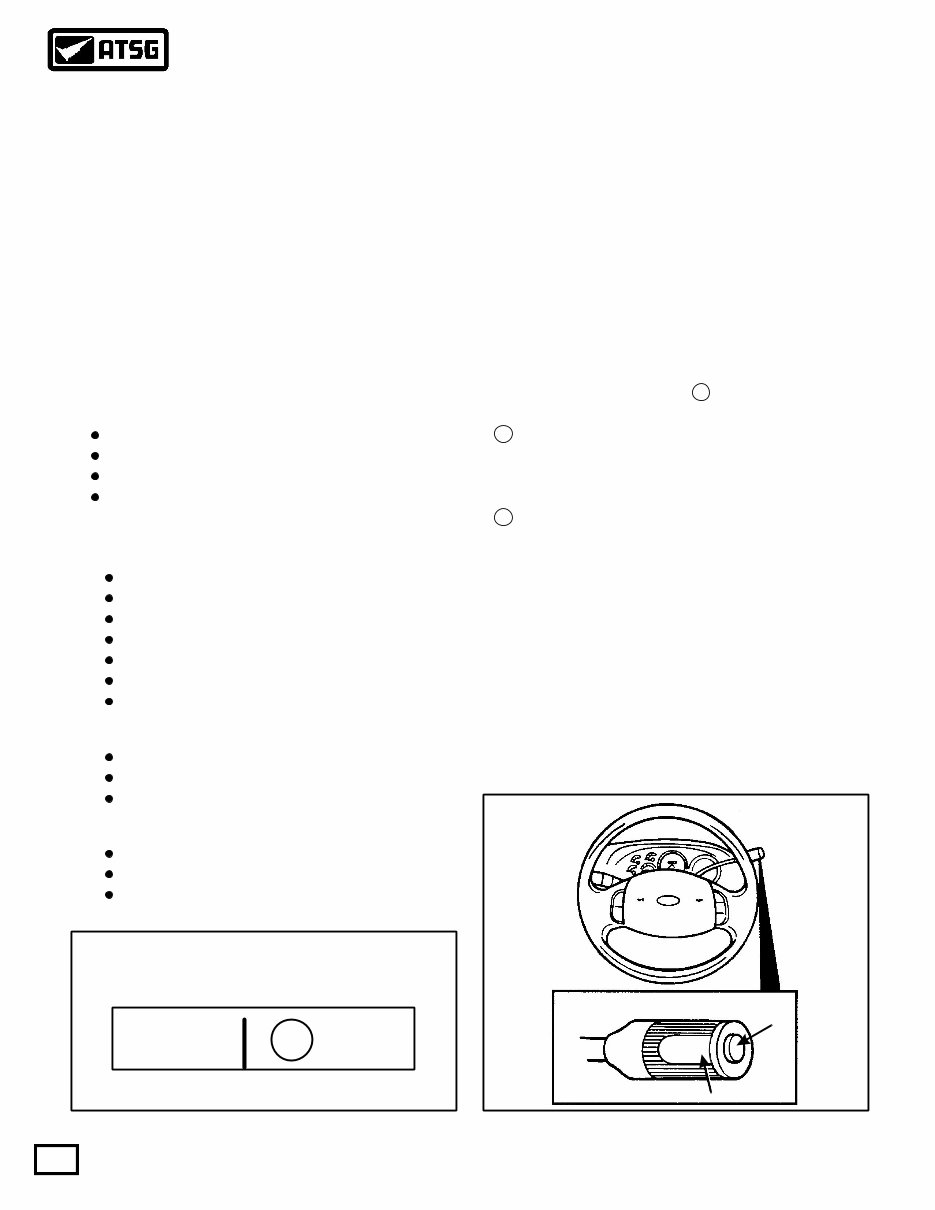
General Description
Shift Quadrant Indicator
Major Internal Components
"Seven Friction Apply Elements"
"Three One-Way Clutches"
"Three Simple Planetary Gearsets"
"Typical" Shift Quadrant Indicator
The Ford 4R100 automatic transmission is a four
forward speed unit with electronic shift control. It is
designed for longitudinal powertrains for rear wheel
drive vehicles.
The 4R100 transmission features a four element
torque converter design that includes Torque
Converter Clutch (TCC) and a gear train that includes
three planetary gearsets.
Some models provide for Power Take Off (PTO)
operation in all transmission shift lever positions.
During PTO operation in OD, 4th gear is disabled.
The hydraulic control system of the 4R100 unit has
five electronically controlled solenoids for:
Shift feel, through line pressure control.
Shift scheduling, through shift valve position.
Engine braking during coast conditions.
TCC apply (On/Off or Modulating).
Intermediate Band
Coast Clutch, Multi-disc
Overdrive Clutch, Multi-disc
Intermediate Clutch, Multi-disc
Direct Clutch, Multi-disc
Forward Clutch, Multi-disc
Low/Reverse Clutch, Multi-disc
Overdrive Roller Clutch
Intermediate Sprag
Low Roller Clutch
Overdrive
Forward
Reverse
PRND21
Figure 2 Figure 3
Vehicles equipped with the 4R100 transmission have
a Transmission Control Switch (TCS), also referred to
as "Overdrive Cancel Switch", and a Transmission
Control Indicator Lamp (TCIL), located on the end of
the manual gear shift lever, as shown in Figure 3. The
TCS is a momentary contact switch. When this
switch is pressed, a signal is sent to the PCM to allow
automatic shifts from 1st to 4th gear or from 1st to 3rd
gear. After the TCS has been pressed the PCM turns
on the TCIL lamp ("OFF"), to indicate that overdrive
has been canceled, as shown in Figure 3.
OVERDRIVE OFF OVERDRIVE OFF
TCS
SWITCH
TCIL LAMP
The shift quadrant has the following positions, as
shown in Figure 2: P, R, N, D , 2 and 1.
D position (TCS OFF) provides 1-2-3-4 automatic
upshifts and downshifts. Coast braking occurs in 4th
gear. (TCIL Not Illuminated)
D position (TCS ON) provides 1-2-3 automatic
upshifts and downshifts. Coast braking occurs in 3rd
gear. (TCIL Illuminated)
2 position provides a pull-in shift to 3rd gear with
coast braking. After an automatic downshift, a 2nd
gear hold occurs with coast braking.
1 position provides a pull-in shift to 2nd gear with
coast braking. After an automatic downshift, a 1st
gear hold occurs with coast braking.
AUTOMATIC TRANSMISSION SERVICE GROUP
Technical Service Information
5
Copyright © 2003 ATSG
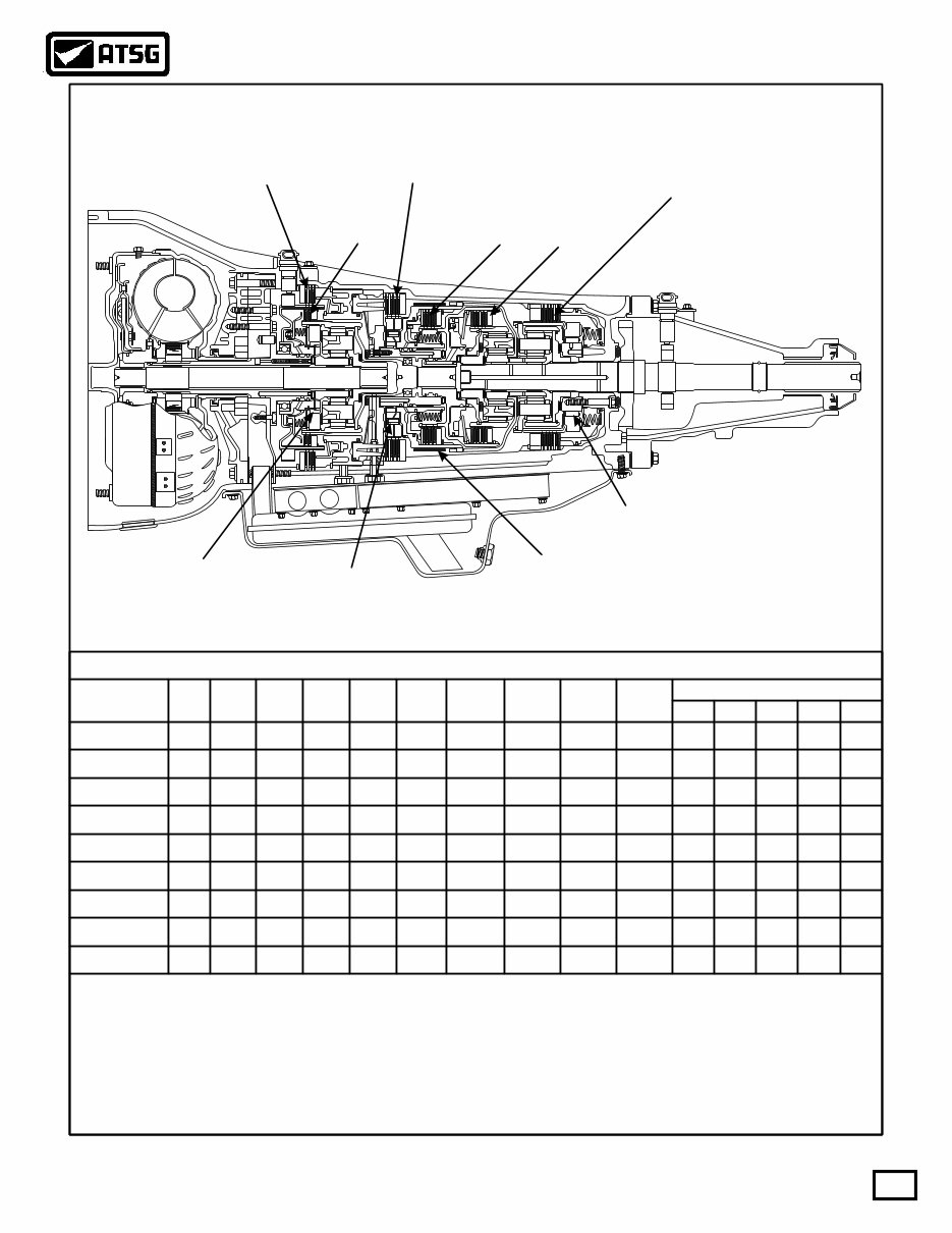
FORD MOTOR COMPANY
4R100 ("PTO" Version Illustrated)
Reverse - 2.18
GEAR RATIOS
Overdrive
Clutch
Overdrive
Roller Clutch
Intermediate
Clutch
Intermediate
Band
Intermediate
Sprag
Coast
Clutch
Forward
Clutch
Direct
Clutch
Low/Reverse
Clutch
Low
Roller Clutch
1st Gear - 2.71
2nd Gear - 1.54
3rd Gear - 1.00
4th Gear - 0.71
Fwd
Clut
ON Hold
Hold
Hold
Hold
Hold Hold
Hold
Hold
Hold
Hold
Hold
ON ON
ON
ON
ON
ON
ON
ON
ON
ON
ON
ON ON
On
On
On *On
*On
*On
*On
*On
*On
On
On
On
On
On
On On
On
Mod
Mod
Mod
Mod
Mod
Mod
Mod
Mod
Mod On
On
Off Off
Off Off Off
Off
Off
Off
*Off
*Off
*Off
Off
Off
Off
Off
Off
Off
ON
ON ON
ON
ON ON
ON
ON
ON
ON
Int
Clut
Int
Band
O.D.
Roller
Low
Roller SS1 SS2 CCS
SOLENOIDS
TCC EPC
Int
Sprag
Dir
Clut
O.D.
Clut
Cst
Clut
L/R
Clut
Park/Neut
Reverse
OD-2nd
OD-3rd
OD-3rd**
OD-3rd** = TCS "On" with TCIL illuminated showing "Off"
OD-4th
M-2nd
M-1st
OD-1st
GEAR
COMPONENT AND SOLENOID APPLICATION CHART
*On = If the PCM determines that powertrain operating conditions exist for TCC apply, the TCC solenoid may
be On (Modulating with PWM TCC units) in any forward gear except Manual 1st.
*Off = Will be "On", if the TCS switch is pushed.
Mod = Modulating at all times by the PCM and line pressure will be regulated based on throttle position,
engine load and vehicle speed.
Figure 4
AUTOMATIC TRANSMISSION SERVICE GROUP
Technical Service Information
6
Copyright © 2003 ATSG
PTO "GENERAL" REQUIREMENTS:
RFF81P-7006-BA
Ford
Ford Ford
98
XW4P-AC
RJL-B
004361
BD-9C17
PTO
Window
Figure 5
(1) Obviously the case must be PTO capable with
the cast-in window in the transmission where the
PTO unit mounts to the transmission, as shown in
Figure 5.
(2) Designed for use during Mobile (Some Models)
or Stationary conditions.
Shift Solenoid 2 and the Coast Clutch Solenoid
must be energized when the PTO is turned ON.
(3) PTO is available as an option only on 8500 GVW
or above, Super Duty F-Series trucks with 6.8L
Gasoline and 7.3L Diesel engines. Ford 4R100
transmissions on other models are not PTO
capable.
(4)
(5)
Battery voltage must be supplied to the
Powertrain Control Module (PCM) input pin 4
on gasoline models, or pin 66 on diesel models,
when the PTO is engaged. The processor uses
this information to raise EPC pressure to
approximately 55 PSI so that you do not burn the
coast clutch. This voltage must be provided by
the PTO installer.
"GENERAL" CONDITIONS FOR OPERATION
(1)
(2)
(3)
(4)
(5)
The vehicle is not in the crank or start mode.
The transmission range selector must be in the P,
R, O.D, 2 or 1 position. The PTO will not operate
when selector is in the neutral position.
PTO operation is inhibited when in cranking
mode, neutral, or 4th gear.
Transmission only operates 1st through 3rd
gears. Computer strategy does not allow 4th
gear to engage, under any conditions.
Transmission Fluid Temperature Sensor (TFT)
reading must be up to operating temperature.
Specific Operation For Diesel, See Page 7.
GASOLINE ENGINE PTO OPERATION:
(1)
(2)
(3)
(4)
PTO installer must obtain a "High Idle Throttle
Control" from an aftermarket source.
Auxiliary Powertrain Control Module seen on
Page seven, does not work on the gasoline engine
models. APCM module works only on the 7.3L
diesel engine.
For stationary PTO operation an engine idle
speed of 1300 RPM is required.
The Torque Converter Clutch (TCC) engages
once the engine reaches 1300 RPM.
TRANSMISSION FUNCTIONS
DURING PTO OPERATION:
(1)
(2)
(3)
(4)
(6)
(5)
Shift Solenoid 2 and Coast Clutch Solenoids are
turned on, the coast clutch activates and does not
allow 4th gear operation during PTO operation.
Electronic Pressure Control (EPC) pressure is
raised to approximately 55 PSI. This is why the
coast clutch will be smoked in a short period of
time if a battery voltage wire is not supplied to
EEC input pin 4 (gasoline) or pin 66 (diesel)
when the PTO is engaged, as this rise in pressure
would not occur.
The Transmission Control Indicator Lamp
(TCIL) illuminates.
When the PTO is turned ON, the transmission
operates only in 1st through 3rd gears.
Overdrive 4th gear is not allowed by the PCM
strategy.
PTO operation can cause transmission fluid
temperature to exceed the recommended
maximum limit of 250 degrees F. Failure mode
logic within PCM strategy prevents transmission
damage by disabling the PTO above this
temperature limit.
The transmission shift schedule is early and shift
feel is very firm.

AUTOMATIC TRANSMISSION SERVICE GROUP
Technical Service Information
7
Copyright © 2003 ATSG
Ford Ford
Ford Ford
RPM
CONTROL
RPM
CONTROL
CHARGE
PROTECT
CHARGE
PROTECT
POWER POWER
2500
AUXILIARY POWERTRAIN CONTROL MODULE AUXILIARY POWERTRAIN CONTROL MODULE
CHARGE PROTECTION APPLICATION
KITS INCLUDE
RPM CONTROL
Charge Protection is used for maintaining battery charge.
In Charge Protection mode, the battery voltage is monitored and the
engine idle speed is increased as necessary, so the battery charge is
maintained as required.
Charge Protection can be activated from in-cab and can be
programmed to activate automatically on engine start-up.
Exclusively for light trucks with the 7.3L Diesel Engine.
Intended for Stationary Use Only.
Order Guide Option Code 961.
Aux. Powertrain Control Module.
Mounting Hardware and Bracket.
Wiring Harness.
Instruction Booklet.
Operators Card.
LCD screen displays the current
engine speed or battery voltage.
Each Single Arrow key contains a
preset speed allowing for four
programmable RPM settings.
The Double Arrow keys can also be
used to manually raise or lower the
engine speed at a faster or slower
rate.
RPM Control is used for
This is the recommended
method of elevating idle
speed for PTO operations.
RPM Control mode can be
activated from in-cab and
can be programmed to
activate automatically on
engine start-up.
The programmable speed
presets range from 1300 to
"AUXILIARY" POWERTRAIN CONTROL MODULE
7.3L DIESEL ENGINE (ONLY)
The Auxiliary Powertrain Control Module (APCM) commands the Electronic Engine Control
(EEC) module to increase the idle speed during PTO operation. The APCM controls engine
speed from 1300 to 2500 RPM.
The Auxiliary Powertrain Control Module is a seperate option, it does not come standard with a
PTO capable transmission, and is for 7.3L diesel applications only.
Intended for stationary use only, and in stationary operation the PTO requires an engine idle speed
of 1300 RPM. During stationary PTO operation on the 7.3L diesel, the EEC increases the idle to
1300 RPM automatically.
During stationary PTO operation, the Torque Converter Clutch (TCC) engages once the RPM
reaches 1200-1300 RPM.
The following conditions must be met before the idle speed is increased:
1. Parking brake must be engaged for all applications.
2. No hydraulic brake actuation.
3. Accelerator pedal must be in the idle position.
4. Vehicle speed must be zero MPH.
5. Brake lights must be functional.
DIESEL ENGINE PTO OPERATION:
Figure 6

DIAGNOSTIC CONCERNS WITH PTO
EQUIPPED VEHICLES:
ELECTRICAL COMPONENT DIAGNOSIS
(1)
(2)
(3)
(4)
Always ensure that PTO is turned OFF, before
any diagnostic procedures begin.
Never perform any transmission special tests
(i.e. pressure test, stall test etc.) when the PTO is
turned ON.
If a transmission concern or symptom goes
away with the PTO turned OFF, it is most likely
not a transmission concern.
On Board Diagnostics operate normally during
PTO operation with the exception of the engine
misfire monitor. The circuit checks made by the
PCM and Failure Mode Effect Management
(FMEM) capability will continue. The PTO
must be turned OFF to access Diagnostic
Trouble Codes (DTC's) and perform OBD tests.
Caution: If the batteries are disconnected for any
reason, the PCM "must" have a 7 mile drive cycle at
speeds above 50 MPH, before it remembers that it is
capable of running a PTO
AUTOMATIC TRANSMISSION SERVICE GROUP
Technical Service Information
8
Copyright © 2003 ATSG
Accelerator Pedal Position Sensor (Diesel Only)
4X4 Low Switch
The Accelerator Pedal (AP) position sensor is
mounted on the accelerator pedal inside the vehicle
and detects the position of the accelerator pedal and
sends this information as a varying voltage signal to
the PCM. The PCM then uses the monitored voltage
level of the AP sensor for control of EPC pressure and
shift scheduling.
The Idle Validation Switch is fed voltage through
fuse number 19, as well as the Transmission Control
Switch, as shown in Figure 7.
If the Idle Validation Switch feed voltage is lost for
any reason, the engine will immediately return to
idle and stay there until feed voltage is restored.
FUSE 19
Red/Yellow
Transmission Control Switch (TCS)
Clutch Pedal Position (CPP) (Std Trans Only)
Idle Validation Switch (IVS) (Diesel Only)
Overhead Trip Computer Module
Generic Electronic Module (GEM)
Instrument Cluster Terminal A12
Instrument Cluster Terminal B11
CENTRAL JUNCTION BOX
Figure 7
Figure 8
The 4X4 Low Switch is used to the PCM that the
transfer case system is operating in LOW range. The
PCM receives the 4X4 Low Switch input signal and
modifies shift scheduling for the lower gear ratio
(See Figure 8).
If the 4X4 LOW indicator fuse is blown, the
transmission will shift according to the 4X4 LOW
shift schedule, regardless of transfer case lever
position.
PCM PIN 14
Lt. Blue/Black
AUTOMATIC TRANSMISSION SERVICE GROUP
Technical Service Information
9
Copyright © 2003 ATSG
Copyright © 2003 ATSG
Turbine Shaft Speed Sensor
PTO Models Only = 496-1244 Ohms Resistance
Part Number F81Z-7M101-BA
Non PTO Models Only = 781-1979 Ohms Resistance
Part Number F81Z-7M101-AA
Copyright © 2003 ATSG
Output Shaft Speed Sensor
All Models = 781-1979 Ohms Resistance
Part Number F81Z-7M101-AA
Turbine Shaft Speed Sensor Output Shaft Speed Sensor
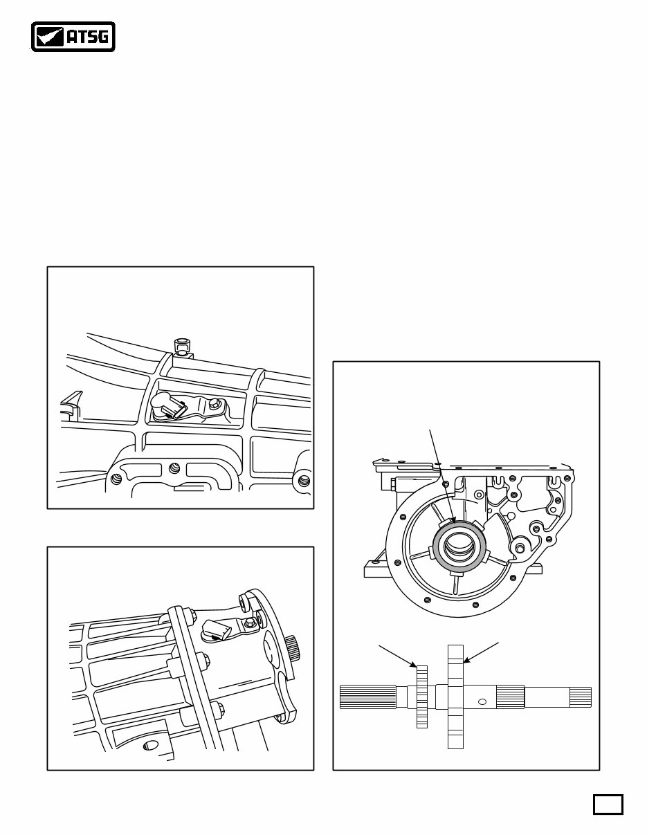
The Output Shaft Speed (OSS) sensor is a magnetic
pickup that sends the PCM a frequency signal related
to the rotating speed of the transmission output shaft.
The OSS sensor was added to the top of extension
housing, as shown in Figure 10. The OSS is triggered
by an added rotor pressed onto the output shaft. The
park gear is also now pressed onto the output shaft,
and the number 13 thrust washer has changed to a
thrust bearing, as shown in Figure 11. We have
provided you with the resistance reading and the
OEM part number for the output shaft speed sensor.
Refer to Figure 10 for output shaft speed sensor
information.
The PCM uses the OSS sensor signal to control EPC
pressure, shift scheduling and TCC strategy.
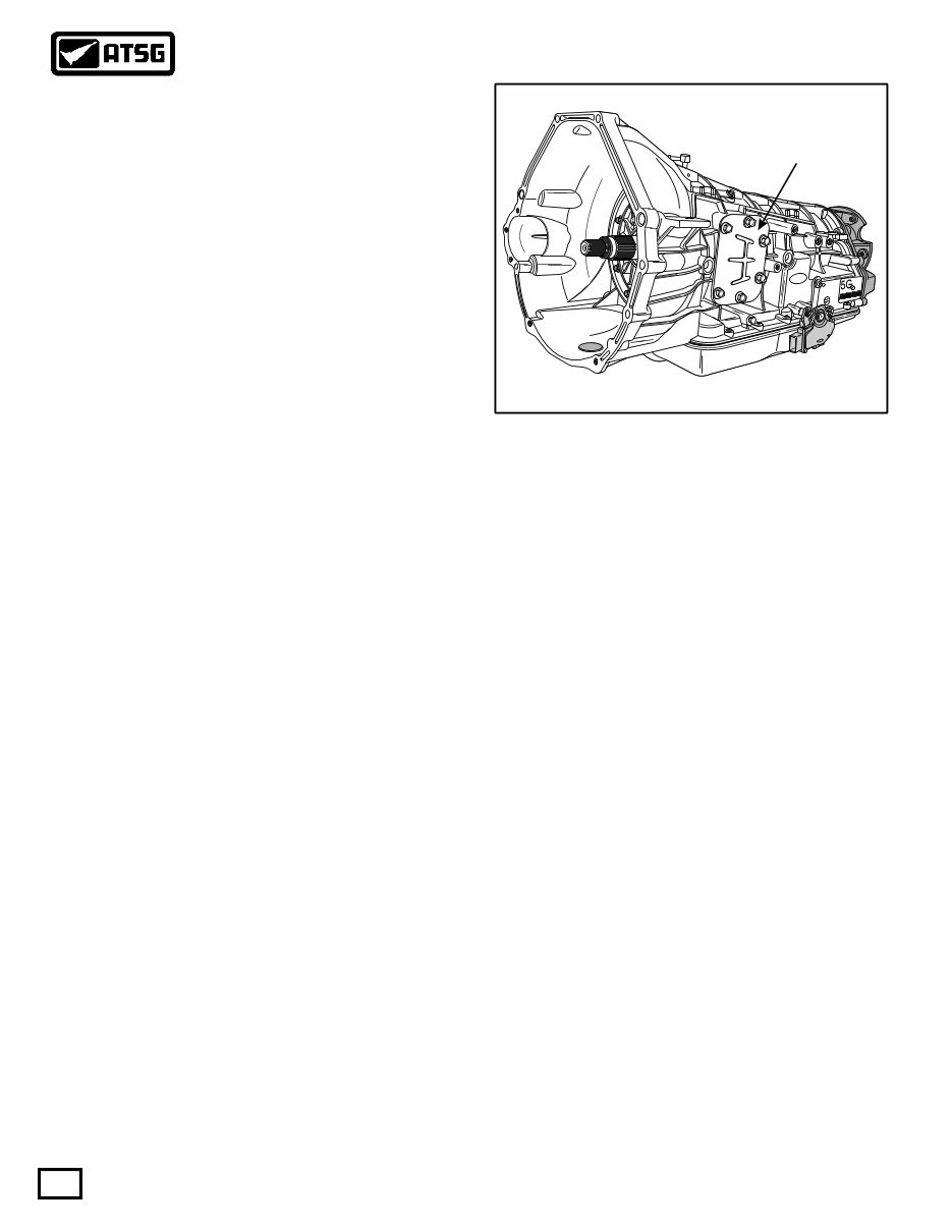
The Turbine Shaft Speed (TSS) sensor is a magnetic
pickup that sends the PCM a frequency signal related
to the rotating speed of the transmission input shaft.
The TSS mounts on the top front of the case on some
models, as shown in Figure 9. We have also provided
you with the resistance readings and OEM part
numbers on both Turbine Speed Sensors, as the PTO
and Non-PTO models use different sensors, as shown
in Figure 9.
The PCM uses the TSS sensor signal to control EPC
pressure and TCC strategy.
Figure 9
Figure 10 Figure 11
The Park Gear is also a press fit to the output
shaft, and the number 13 thrust washer, between
the case and the park gear has been replaced
with a needle bearing.
OSS Rotor Park Gear
(Press Fit) (Press Fit)
ELECTRICAL COMPONENT DIAGNOSIS DTR TESTING PROCEDURE
AUTOMATIC TRANSMISSION SERVICE GROUP
Technical Service Information
10
Copyright © 2003 ATSG
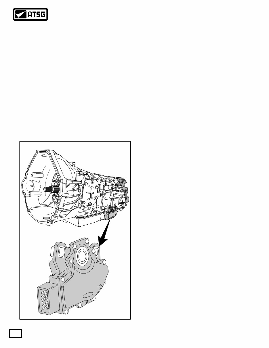
Digital Transmission Range Sensor
The Digital Transmission Range (DTR) sensor has a
twelve pin electrical connector and is located on the
outside of the transmission at the manual lever, as
shown in Figure 12.
The DTR sensor completes the start circuit in Park
and Neutral, the backup lamp circuit in Reverse, and
the neutral sense circuit (4WD Only) when in Neutral.
The DTR sensor also opens or closes a set of four
different switches that are monitored by the
Powertrain Control Module (PCM) to determine the
position of the transmission manual lever. Refer to
Figure 13.
Figure 12
Ford
F7TP-7F293-AA
NEUTRAL
L
C
RFF81P-7006-BA
Ford
Ford Ford
98
XW4P-AC
RJL-B
004361
BD-9C17
In Figure 13 we have provided you with pin number
identification for both the transmission range sensor
and the vehicle harness. We have also provided a
chart that will give you the open/closed state of each
internal switch, dependent on selector position, and
notice that three positions read a 270Ω resistor, that is
also internal.
Note: All testing that we have provided for you is
done with a DVOM, set to the ohms position, and all
tests are performed with the ignition switch in the
"OFF" position.
(1) Testing the transmission range 3A switch, and
the 270Ω internal resistor is done across pins 2
and 3 of the DTR sensor, and must be checked in
each selector position to determine the switch
and resistor integrity. Refer to Figure 13.
(2) Testing the transmission range 1 switch is done
across pins 2 and 4 of the DTR sensor, and must
be checked in each selector position to
determine switch integrity. Refer to Figure 13.
(3)
(4)
(5)
(6)
Testing the transmission range 2 switch is done
across pins 2 and 5 of the DTR sensor, and must
be checked in each selector position to
determine switch integrity. Refer to Figure 13.
Testing the transmission range 4 switch is done
across pins 2 and 6 of the DTR sensor, and must
be checked in each selector position to
determine switch integrity. Refer to Figure 13.
Testing the reverse lamp circuit is done across
pins 9 and 11 of the DTR sensor, and must be
checked in each selector position to determine
switch integrity. Refer to Figure 13.
Testing the neutral start circuit is done across
pins 10 and 12 of the DTR sensor, and must be
checked in each selector position to determine
switch integrity. Refer to Figure 13.
You're Reading a Preview
What's Included?
Fast Download Speeds
Online & Offline Access
Access PDF Contents & Bookmarks
Full Search Facility
Print one or all pages of your manual
$31.99
Viewed 54 Times Today


Secure transaction
What's Included?
Fast Download Speeds
Online & Offline Access
Access PDF Contents & Bookmarks
Full Search Facility
Print one or all pages of your manual
$31.99
The Ford 4R100 4-Speed Automatic Transmission Service & Repair Manual is an indispensable tool for any automotive professional or enthusiast servicing and maintaining Ford vehicles equipped with the 4R100 transmission. This detailed manual covers all aspects of service, repair, and maintenance:
- Comprehensive Service Instructions: Detailed procedures for servicing the 4R100 transmission, including fluid changes, filter replacement, and system diagnostics.
- Troubleshooting Guidelines: Diagnostic strategies and troubleshooting steps to help quickly resolve problems and restore transmission performance.
- Repair Procedures: Step-by-step repair instructions to tackle complex transmission issues, from minor adjustments to major rebuilds.
- Technical Specifications: Complete technical specs of the transmission, including torque specifications, capacities, and detailed assembly diagrams.
- Preventative Maintenance: Recommended maintenance schedules to extend the life of the transmission and avoid costly repairs down the line.
This manual is a must-have for maintaining the integrity and performance of Ford 4R100 transmissions. It provides the knowledge needed to ensure reliable operation, making it an invaluable resource for achieving professional-quality results in any setting.


