

EATON RT RTO RTLO RTLOF RTX RTF Gearbox Workshop Manual
What's Included?
Fast Download Speeds
Offline Viewing
Access Contents & Bookmarks
Full Search Facility
Print one or all pages of your manual

Fuller
®
Heavy Duty Transmissions
Service Manual
Fuller Heavy Duty Transmissions
TRSM0515
October 2007
More time on the road
®

TABLE OF CONTENTS
Timing
Description
Operations
Lubrication
Preventive Maintenance
Torque Recommendations
Air System
Precautions
Disassembly
Front Section Disassembly
Auxiliary Disassembly
Auxiliary Reassembly
Front Section Reassembly
Reassembly
Tool Reference
Changing Clutch (Input Shaft)
Eaton Corporation
Transmission Division
Kalamazoo, Mich. 49007
It is essential that the two countershafts are timed.
This assures that the countershaft gears will con-
tact the mating mainshaft gears at the same
instant, allowing the mainshaft gears to seek their
equilibrium position. This prohibits the mainshaft
gears from climbing out of position and prevents
unequal tooth contact.
Timing one set of gears, the drive gear set, is all
that is necessary. It is a simple procedure, consist-
ing of marking the proper teeth prior to installation
and meshing the teeth so marked.
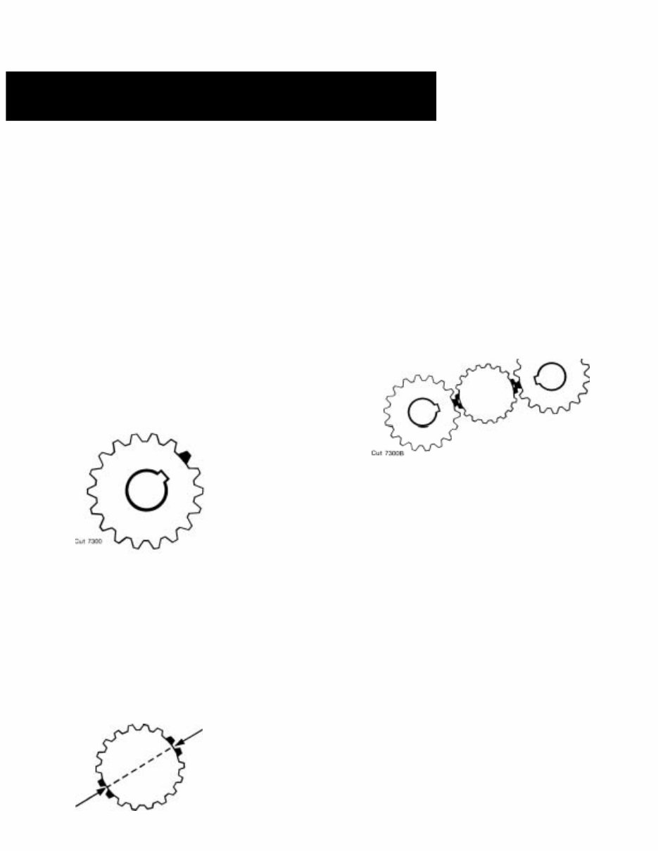
A. Marking countershaft drive gear teeth.
1. Prior to placing each countershaft assem-
bly into case, clearly mark on each drive
gear the gear tooth which is directly over the
keyway in gear. (See illustration A.) This
tooth is stamped with an "O" to aid iden-
tification.
A. TOOTH ON
COUNTERSHAFT
DIRECTLY OVER
KEYWAY MARKED
FOR TIMING
B. Marking drive gear teeth.
1. Mark any two adjacent teeth on the drive
gear.
2. Mark the two adjacent teeth on the drive
gear which are directly opposite the first set
marked. There should be an equal number
of teeth between the markings on each side
of gear. (See Illustration B.)
B. DRIVE GEAR TEETH
Cut 7300A CORRECTLY MARKED
FOR TIMING
C. Meshing marked countershaft gear
teeth with marked drive gear teeth.
(After installing drive gear and main-
shaft assemblies, the countershaft
bearings are installed to complete
countershaft installation.)
1. When installing bearings on the left
countershaft, mesh the marked counter-
shaft gear tooth between two marked teeth
on the drive gear. Repeat the procedure
when installing the right countershaft bear-
ings. (See Illustration C.)
C. COUNTERSHAFT GEAR TEETH
MESHED WITH DRIVE GEAR TEETH
FOR CORRECT TIMING
D. Timing auxiliary section.
(In the auxiliary section, the low speed gear set
is marked for timing instead of the drive gear
set.)
1.
2.
3.
4.
5.
6.
Mark any two adjacent teeth on the large
mainshaft low speed gear, then mark the
two adjacent teeth directly opposite„the
same procedure as used when marking the
front section drive gear.
On each auxiliary countershaft assembly,
mark the tooth on the small low speed gear
which is stamped with an "O".
Install the low speed gear and tailshaft
assembly in auxiliary housing.
Partially install outer races of countershaft
rear bearings in case bores.
Place the auxiliary countershaft assem-
semblies into position, meshing marked
tooth on each countershaft gear between
marked teeth on low speed gear. Counter-
shafts will be partially seated in rear bear-
ing.
Fully install rear bearings to complete aux-
iliary countershaft installation.
TIMIMG
DESCRIPTION
SHIFTING THE
10 SPEED ROADRANGER TRANSMISSION
RT-661O SERIES
General Instructions
The 10-speed Roadranger Transmissions provide
ten selective ratios, evenly and progressively spac-
ed and shifted with one lever. But you do NOT shift
the Roadranger as you would a conventional
transmission with an auxiliary or 2-speed axle,
because there is no split-shifting.
The shifting of the 10-speed Roadranger Trans-
missions is much simpler.. much easier,
ALL SHIFTS ARE MADE WITH ONE LEVER . . .
you use the RANGE CONTROL BUTTON ONE
TIME ONLY during a sequence of up-shifts . . .and
ONE TIME ONLY during a down-shift pattern.
Why is the Roadranger different?
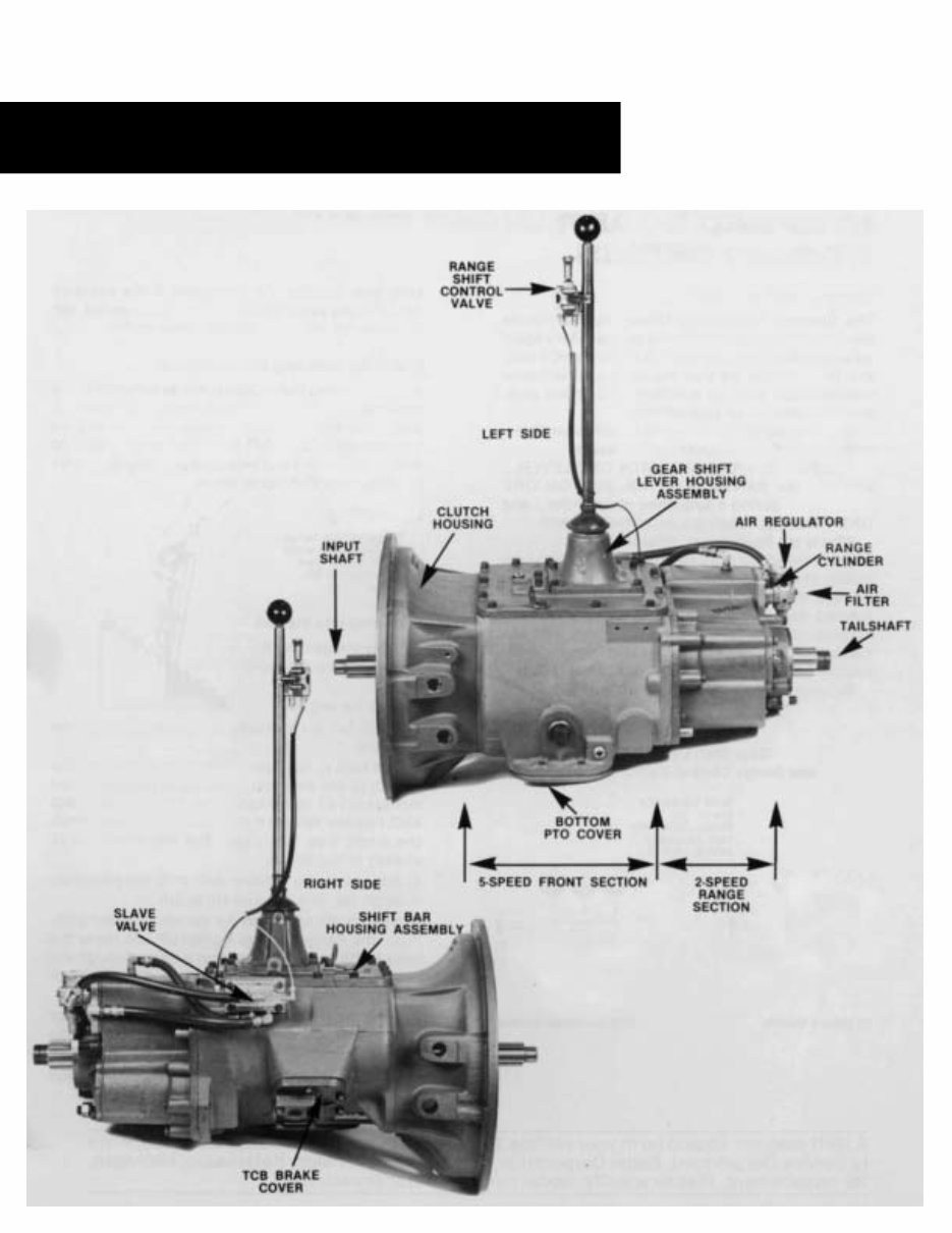
The Roadranger is a 2-RANGE transmission con-
sisting of a5-speed front section and an automatic
2-speed auxiliary section in ONE CASE. The ten
forward speeds are secured by using a 5-speed
shifting pattern TWICE–the first time with the
transmission engaged in Iow gear or low range; the
second time engaged in high gear or high range.
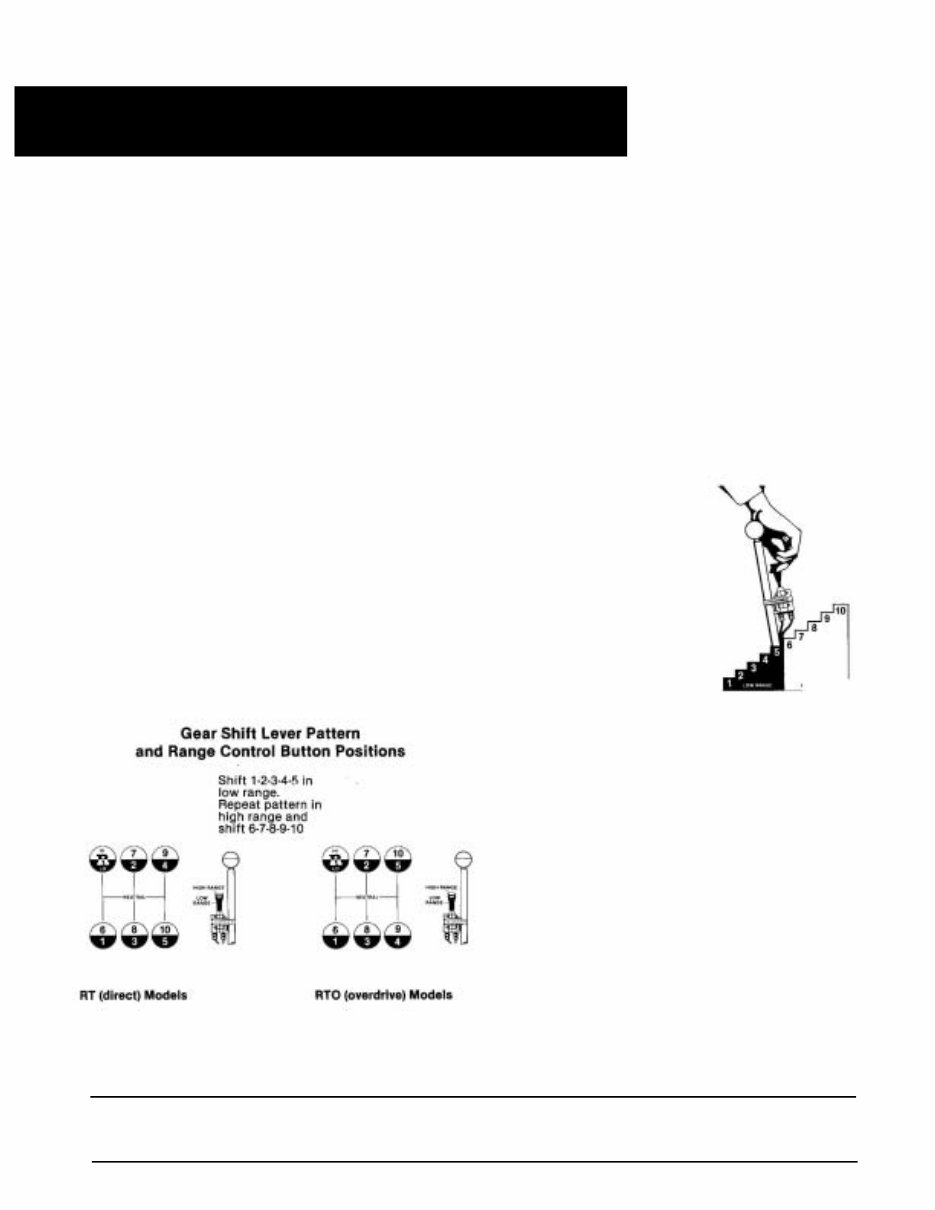
By using the same shifting pattern twice, the
shift lever position for 6th speed is the same as
lst...7th the same as 2nd, 8th the same as 3rd, 9th
the same as 4th, and 10th the same as 5th.
Detailed Shifting Instructions
In the following instructions, it is assumed that the
driver is familiar with motor trucks and tractors,
and that he can coordinate the necessary
movements of the shift lever and clutch pedal to
make progressive and selective gear engagements
in either direction, up or down.
Upshifting
To get to high range
pull button UP while
in 5th speed, then
move lever to 6th
speed.
Let's step into the cab.
1. Move the gear shift
lever to the neutral posi-
tion.
2. Start the engine.
3. Wait for air system to reach normal line
pressure.
4. Now look at the Range Control Button. If it is up
push it to the down position. (With the downward
movement of the button, the transmission will
shift into low range.) If the button was down when
the truck was last used, the transmission is
already in low range.
5. Now start the vehicle and shift progressively
through 1st, 2nd, 3rd and 4th to 5th.
6. When is 5th and ready for the next upward shift,
PULL the Range Control Button UP and move the
lever to 6th speed. As the Iever passes through the
neutral position, the transmission will automati-
cally shift from low range to high range.
7. With the transmission in high range, you may
now shift progressively through 7th, 8th and 9th to
10th.
Driving tip: always start vehicle moving in first
speed gear.
A shift diagram should be in your vehicle. If your shift diagram has been misplaced, write
to Service Department, Eaton Corporation, Transmission Division, Kalamazoo, Michigan,
for replacement. Please specify model number of transmission.
OPERATION
You're Reading a Preview
What's Included?
Fast Download Speeds
Offline Viewing
Access Contents & Bookmarks
Full Search Facility
Print one or all pages of your manual
$44.99
Viewed 18 Times Today


Secure transaction
What's Included?
Fast Download Speeds
Offline Viewing
Access Contents & Bookmarks
Full Search Facility
Print one or all pages of your manual
$44.99
This workshop service repair manual covers the following models:
- RT
- RTF
- RTO
- RTOF
- RTX
- RTXF
- RTLO
- RTAO
- RTLOF
- FS
- FSB
- FSO series transmission
It includes a parts list and comprehensive content such as:
- General information
- General service practices
- Part inspection
- How to use this manual
- Model designation
- Power flow
- Timing procedures
- Tool reference
- Preventive maintenance
- Lubrication
- Inspection
- Rear seal maintenance
- External parts disassembly and assembly
- Air lines and hose removal and installation
- Air filter/regulator removal and installation
- Roadranger valve removal and installation
- Range actuator valve removal and installation
- Top 2 valve assembly removal and installation
- Gear shift lever removal and installation
- Shift bar housing removal and installation
- Output yoke/companion flange removal and installation
- Auxiliary section removal and assembly
- Clutch housing removal
- Input shaft removal and installation
- Gear shift lever disassembly and assembly
- Standard shift bar housing disassembly and assembly
- Front section and auxiliary section disassembly
- Front auxiliary drive gear removal and installation
- Countershaft assemblies removal and assembly
- Output shaft assembly
- Range cylinder assembly
- Rear auxiliary drive gear installation
- Splitter cylinder assembly
- Synchronizer assembly disassembly
- Integral oil pump removal and installation
This comprehensive manual provides detailed exploded views and step-by-step procedures with illustrations, making it an essential resource for professional mechanics and DIY enthusiasts for gearbox repairs, maintenance, and servicing.


