

Delphi DP210 Fuel Injection Pump OEM Service & Repair Manual
What's Included?
Fast Download Speeds
Online & Offline Access
Access PDF Contents & Bookmarks
Full Search Facility
Print one or all pages of your manual
WORKSHOP MANUAL
DP210 FUEL INJECTION PUMP DDNX184(EN)
2003
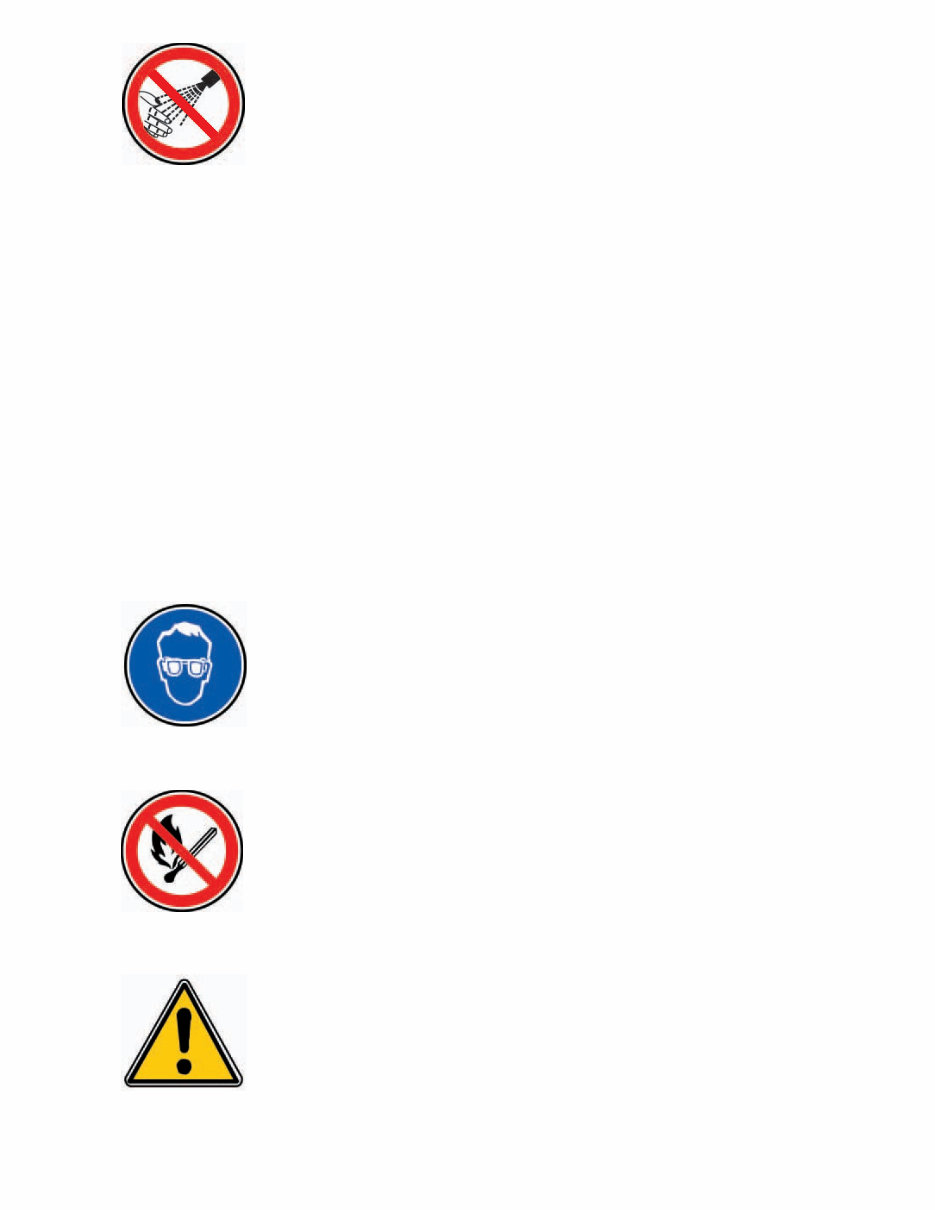
(D) Schutzbrille/Gesichtsschutz tragen.
(E) Úsese protección para los ojos/la cara.
(EN) Wear eye/face protection.
(F) Porter un appareil de protection des yeux / du visage.
(IT) Proteggersi gli occhi/la faccia.
(NL) Veiligheidsbril/-masker gebruiken.
(P) Use protecção da face/olhos.
(D) Von Zündquellen fernhalten - Nicht rauchen.
(E) Conservar alejado de toda llama o fuente de chispas -No fumar.
(EN) Keep away from sources of ignition - No smoking.
(F) Conserver à l'écart de toute flamme ou source d'étincelles - Ne pas fumer.
(IT) Conservare lontano da fiamme e scintille - Non fumare.
(NL) Ver van open vuur en ontstekingsbronnen houden – Niet roken.
(P) Mantenha afastado de fontes de ignição – Proibido fumar.
(D) Geeignete Schutzhandschuhe tragen.
(E) Usen guantes adecuados.
(EN) Wear suitable gloves.
(F) Porter des gants appropriés.
(IT) Usare guanti adatti.
(NL) Aangepaste veiligheidshandschoenen dragen.
(P) Use luvas apropriadas.
(D) Kommen Sie nicht mit dem Hochdruckstrahl in Verbindung! Besonders nicht, wenn
Druckrohrleitung oder Dichtung geprüft werden! Hochdruckflüssigkeiten können tödli-
che Verletzungen verursachen! Im Falle einer Berührung mit der Haut, kontaktieren Sie
sofort einen Arzt. Bitte beachten Sie die Gesundheits-/und Sicherheitsunterlagen.
(E) Mantenga las manos y el cuerpo lejos del rociado del líquido, especialmente inyecto-
res, tuberías y juntas de alta presión con fugas. La inyección de alta presión puede per-
forar la piel humana y producir una lesión fatal. En caso de que la inyección atraviese
la piel, consiga atención médica inmediatamente. Vea la hoja de Datos de Sanidad y
Seguridad.
(EN) Do not put your skin into the fuel jets under pressure, especially those due to pressure
pipe or seal leaks. High pressure liquids can cause deadly injuries. In case of an injec-
tion under the skin, contact a doctor immediately. Please refer to the health and secu-
rity fuel documents.
(F) Ne pas approcher les mains ni le corps des jets de liquides, particulièrement ceux pro-
venant des fuites de tuyaux et des joint soumis a la haute pression. Le liquide sous
haute pression injecté sous la peau peut causer des blessures mortelles. En cas d’in-
jection sous la peau, consulter immédiatement un médecin. Se reporter a la fiche de
santé et de sécurité du gazole.
(IT) Non esporre le mani o altre parti del corpo a getti di gasolio ad alta pressione, spe-
cialmente a quelli provenienti da tubi o paraolii. I getti di liquidi ad alta pressione pos-
sono causare ferite anche mortali. In caso di iniezione sotto pelle contattare immedia-
tamente un medico. Fare riferimento alle schede di sicurezza del gasolio.
(NL) Zorg dat uw handen of andere lichaamsdelen niet in contact komen met vloeistofstra-
len onder hoge druk, met name bij een lek aan een leiding of dichting. Als de vloeistof
onder hoge druk onder de huid terechtkomt, kan dit zelfs tot dodelijke verwondingen
leiden. Als de vloeistof onder de huid terechtkomt, onmiddellijk een arts raadplegen.
Lees de gezondheids- en veiligheidsfiche met betrekking tot de brandstof.
(P) Não exponha a pele a jactos de combustível sob pressão, especialmente os devidos a
fugas de tubos de pressão ou vedantes. Líquidos a alta pressão podem causar ferimen-
tos mortais. No caso de injecção subcutânea, consulte imediatamente um médico.
Consulte por favor a documentação respeitante a saúde e segurança de combustíveis.
CONTENTS
© Delphi Diesel Systems UK Ltd
Publication N°: DDNX184(EN) 2K/03.03/FOLIUM i
INTRODUCTION 1
DISMANTLING 2
COMPONENT INSPECTION AND RENEWAL 3
REASSEMBLY 4
TEST PROCEDURE 5
TOOLING, TORQUES & EVDS 6

BC - Boost Control
CA - Cold Advance
CP - Zero Backlash Drive
CPS - Carriage Position Sensor
DCU - Diesel Control Unit
ESOS - Electric Shut-Off Solenoid
EVD - Exploded View Diagram
FIE - Fuel injection Equipment
HP - High Pressure
LLA - Light Load Advance
OEM - Original Equipment Manufacturer
SIN - Service Instruction Note
TP - Transfer Pressure
NOTATIONAL CONVENTIONS AND ABBREVIATIONS
ii
Produced by:
Delphi Diesel Aftermarket Operations
Stratford Road
Shirley, Solihull Tel.: (44) (0)121 746 6000
B90 4DT, UK Fax: (44) (0)121 746 6001

1 INTRODUCTION
1.1 The Pump .........................................................................................................................................................................7
1.2 General ........................................................................................................................................................................7 - 8
1.3 This Manual ......................................................................................................................................................................8
1.4 Equipment ........................................................................................................................................................................8
1.5 Replacement of Parts.......................................................................................................................................................8
1.6 Pump Name Plate .......................................................................................................................................................8 - 9
2 DISMANTLING
2.1 Preparation .....................................................................................................................................................................11
2.1.1 Cleaning and draining ........................................................................................................................................11
2.1.2 Mounting the pump ...........................................................................................................................................11
2.1.3 Sealing caps and drive shaft lock bolt..............................................................................................................11
2.1.4 Drive hub (if fitted) .............................................................................................................................................12
2.1.5 Measuring drive shaft end float ........................................................................................................................12
2.1.6 Measuring drive shaft radial play .....................................................................................................................12
2.2 Drive Shaft ......................................................................................................................................................................13
2.3 High Pressure Outlets and End Plate Assembly .........................................................................................................13
2.3.1 High pressure outlets ........................................................................................................................................13
2.3.2 Endplate assembly .....................................................................................................................................13 - 14
2.4 Electric Shut-off Solenoid (ESOS) ................................................................................................................................14
2.5 Transfer Pump ................................................................................................................................................................14
2.6 Governor Cover External Components .......................................................................................................................15
2.6.1 Fuel return connections ....................................................................................................................................15
2.6.2 Throttle lever stop screws, maximum fuel adjuster blanking plug and torque control screw ..................15
2.6.3 Throttle lever ......................................................................................................................................................16
2.7 Governor Cover .............................................................................................................................................................16
2.7.1 Governor cover with torque control only ................................................................................................16 - 17
2.7.2 Governor cover fitted with boost control ................................................................................................17 - 19
2.8 All Speed Governor ......................................................................................................................................................19
2.9 Governor Control Bracket and Arm Assembly ..........................................................................................................19
2.9.1 Scroll link plate return spring ...................................................................................................................19 - 20
2.9.2 Governor control bracket assembly ................................................................................................................20
2.9.3 Governor control arm assembly ......................................................................................................................20
2.10 Slackening the Transfer Pump Rotor ..........................................................................................................................20
2.11 Advance Device .....................................................................................................................................................20 - 21
2.11.1 Cam screw...........................................................................................................................................................22
2.12. Head Locating Fittings and Hydraulic Head ................................................................................................................22
2.12.1 Head locking screws...........................................................................................................................................22
2.12.2 Light load advance (LLA) ...................................................................................................................................22
2.12.3 Latch valve ..........................................................................................................................................................22
2.12.4 Releasing the hydraulic head ............................................................................................................................23
2.12.5 Drive assembly ...........................................................................................................................................23 - 24
2.13 Drive Shaft Seal(s) ........................................................................................................................................................24
3 COMPONENT INSPECTION AND RENEWAL
3.1 Cleaning ..........................................................................................................................................................................25
3.2 General............................................................................................................................................................................25
3.2.1 Mated and matched assemblies .......................................................................................................................25
3.2.2 Examination and replacement ..........................................................................................................................25
CONTENTS
iii

3.2.3 Seals ....................................................................................................................................................................25
3.3 Details .............................................................................................................................................................................25
3.3.1 Hydraulic head rotor ..........................................................................................................................................25
3.3.2 Hydraulic head plungers ....................................................................................................................................25
3.3.3 Cam ring and scroll plates .................................................................................................................................25
3.3.4 Rollers and shoes ...............................................................................................................................................25
3.3.5 Transfer pump .............................................................................................................................................25 - 26
3.3.6 Endplate...............................................................................................................................................................26
3.3.7 Control valves .....................................................................................................................................................26
3.3.8 Delivery valves and cambox pressurising valves ...........................................................................................26
3.3.9 Springs ................................................................................................................................................................26
3.3.10 Fittings and threads............................................................................................................................................26
3.3.11 Linkages...............................................................................................................................................................26
3.3.12 Throttle shaft .......................................................................................................................................................26
3.3.13 Drive shafts and associated components ........................................................................................................26
3.3.14 Advance device...................................................................................................................................................26
3.3.15 External controls.................................................................................................................................................26
3.3.16 Pump housing.....................................................................................................................................................26
3.3.17 Governor control cover ......................................................................................................................................26
3.3.18 Orifices.................................................................................................................................................................26
3.3.19 Electric shut-off solenoid ...................................................................................................................................26
3.4 Storage ..........................................................................................................................................................................26
3.4.1 New pumps ........................................................................................................................................................26
3.4.2 Overhaul pumps ................................................................................................................................................26
3.4.3 Storage conditions ............................................................................................................................................27
4 REASSEMBLY
4.1 Preparation .....................................................................................................................................................................29
4.1.1 Hydraulic head ....................................................................................................................................................29
4.2 Drive Shaft ......................................................................................................................................................................29
4.2.1 Catch and support plates ...................................................................................................................................29
4.2.2 Rollers and shoes ...............................................................................................................................................29
4.2.3 Governor weight cage ......................................................................................................................................30
4.2.4 Fitting the governor weight assembly to the drive shaft ..............................................................................30
4.2.5 O-ring and rear scroll plate ..............................................................................................................................30
4.2.6 Cam ring, front scroll plate and inner bearing ........................................................................................30 - 31
4.2.7 Drive shaft assembly .........................................................................................................................................31
4.2.8 Fitting the pump housing .................................................................................................................................31
4.3 Drive Shaft Seals, End Float and Radial Play .............................................................................................................31
4.3.1 Drive shaft seals ................................................................................................................................................32
4.3.2 Securing the drive shaft ....................................................................................................................................32
4.3.3 Measuring drive shaft end float ........................................................................................................................32
4.3.4 Measuring drive shaft radial play .....................................................................................................................33
4.4 Hydraulic Head, Cam Screw and Head Locating Fittings ..........................................................................................33
4.4.1 Aligning the hydraulic head ..............................................................................................................................33
4.4.2 Cam advance screw ...........................................................................................................................................33
4.4.3 Head locating fittings .........................................................................................................................................34
4.5 Advance Device ......................................................................................................................................................34 - 35
CONTENTS
iv

CONTENTS
v
4.5.1 Fitting the advance device assembly to the pump housing...........................................................................35
4.5.2 Tightening the head fittings and advance end plates .....................................................................................36
4.6 Governor Control Bracket and Arm Assembly ..................................................................................................................36
4.6.1 Governor control arm assembly .............................................................................................................................36
4.6.2 Fitting the governor control bracket assembly......................................................................................................37
4.6.3 Scroll link plate return spring ..................................................................................................................................37
4.6.4 Setting the governor link length..............................................................................................................................37
4.7 Governor Cover ..............................................................................................................................................................38
4.7.1 Governor covers fitted with boost control .....................................................................................................38 - 39
4.7.2 Governor cover fitted with torque control only.....................................................................................................39
4.7.3 Assembling the torque trimmer ......................................................................................................................39 - 40
4.7.4 Throttle shaft and governor main spring ..............................................................................................................40
4.7.5 Fitting the governor cover .......................................................................................................................................40
4.8 Governor Cover External Components ..............................................................................................................................41
4.8.1 Throttle levers ............................................................................................................................................................41
4.8.2 Throttle lever stop screws, maximum fuel screw and torque control screw.............................................41 - 42
4.8.3 Fuel return connections ............................................................................................................................................42
4.9 Drive Hub, Transfer Pump and Endplate Assembly ........................................................................................................42
4.9.1 Drive hub ...................................................................................................................................................................42
4.9.2 Transfer pump rotor .................................................................................................................................................42
4.9.3 Internal recirculation (if fitted) ................................................................................................................................43
4.9.4 Assembling the transfer pump ...............................................................................................................................43
4.9.5 Endplate assembly ...........................................................................................................................................43 - 44
4.10 ESOS and High Pressure Outlets ........................................................................................................................................44
4.10.1 ESOS ..................................................................................................................................................................44 - 45
4.10.2 High pressure outlets and clamp plate ..................................................................................................................45
4.11 Drive Shaft Lock Bolt, Drain Plug and Cam Advance Screw ...........................................................................................45
4.11.1 Drive shaft lock bolt .................................................................................................................................................45
4.11.2 Drain plug ..................................................................................................................................................................46
4.11.3 Cam advance reading screw ...................................................................................................................................46
4.12 Leak Testing ...........................................................................................................................................................................46
5 TEST PROCEDURE
5.1 Pump Specification ........................................................................................................................................................47
5.1.1 Rotation ...............................................................................................................................................................47
5.1.2 Gov. link length ...................................................................................................................................................47
5.1.3 Plunger diameter ................................................................................................................................................47
5.1.4 Drive type ............................................................................................................................................................47
5.1.5 Pump features.....................................................................................................................................................47
5.1.6 OEM code ............................................................................................................................................................47
5.2 Test Conditions...............................................................................................................................................................48
5.2.1 Test fluid ..............................................................................................................................................................48
5.2.2 Inlet feed pressure ..............................................................................................................................................48
5.2.3 Nozzles.................................................................................................................................................................48
5.2.4 Nozzle opening pressure ...................................................................................................................................48
5.2.5 Nozzle holder ......................................................................................................................................................48
5.2.6 H.P. pipes .............................................................................................................................................................48
5.3 Pre-Test Notes ................................................................................................................................................................49
5.3.1 Introduction .........................................................................................................................................................49
5.3.2 Leak testing .........................................................................................................................................................49

CONTENTS
vi
5.3.3 Test machine drive .............................................................................................................................................49
5.3.4 Pre set notes ................................................................................................................................................49 - 50
5.4 Test Procedure................................................................................................................................................................50
5.4.1 Introduction .........................................................................................................................................................50
5.4.2 Warm-up and stabilisation.................................................................................................................................50
5.4.3 Initial settings .....................................................................................................................................................51
5.4.4 Transfer pressure ........................................................................................................................................51 - 52
5.4.5 Cambox pressure ...............................................................................................................................................52
5.4.6 Speed advance ............................................................................................................................................53 - 54
5.4.7 Cold advance ..............................................................................................................................................54 - 55
5.4.8 Light load advance ......................................................................................................................................55 - 56
5.4.9 Maximum fuel .....................................................................................................................................................56
5.4.10 Torque trimmer ...........................................................................................................................................57 - 58
5.4.11 Boost control .......................................................................................................................................................59
5.4.12 Latch Valve ..........................................................................................................................................................60
5.4.13 Maximum fuel adjustment ................................................................................................................................61
5.4.14 Torque screw ...............................................................................................................................................61 - 62
5.4.15 Governor ......................................................................................................................................................62 - 63
5.4.16 Light Load Valve .................................................................................................................................................63
5.4.17 Idle setting...........................................................................................................................................................64
5.4.18 ESOS ....................................................................................................................................................................65
5.4.19 Timing ..................................................................................................................................................................65
5.5 Overcheck Procedure ....................................................................................................................................................66
5.5.1 Introduction .........................................................................................................................................................66
5.5.2 Pump preparation...............................................................................................................................................66
5.5.3 Test machine drive .............................................................................................................................................66
5.5.4 Overcheck pre-set notes .............................................................................................................................66 - 67
5.5.5 Overcheck test procedure ..................................................................................................................................67
6 TOOLING, TORQUES & EVD’s
6.1 Tooling..........................................................................................................................................................69 - 70
6.2 Torque values......................................................................................................................................................71
6.3 EVD ..............................................................................................................................................................72 - 76
INTRODUCTION
1 - 7
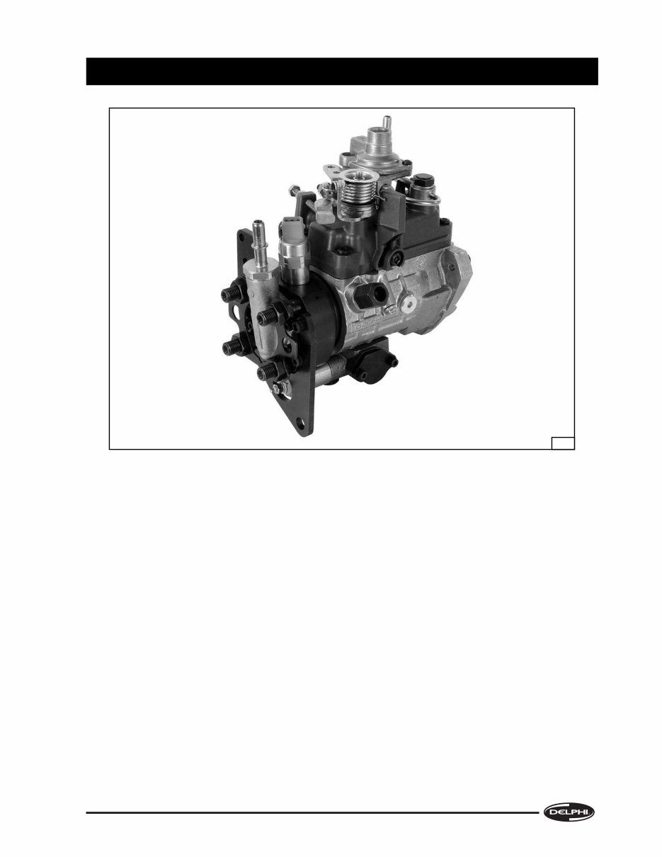
1.1 THE PUMP
The DP210 distributor-type fuel injection pump is a
compact, self-contained unit that is suitable for
direct injection engines of up to 33 BHP per cylinder
and with three, four or six cylinders with either
clockwise or anticlockwise gear drives. It is primarily
intended for diesel engines which have to meet the
Tier 2 off-highway exhaust emissions legislation for
the industrial and agricultural markets in Europe
and USA.
All internal working parts are lubricated by fuel oil
and the pump housing is maintained at an internal
pressure that prevents the ingress of external dirt or
other foreign matter.
Standard features include improved shaft locked
orientation timing, servo controlled light load
advance and speed advance with solenoid switched
cold advance, torque trimmer control of maximum
fuel delivery including excess fuel for starting,
transfer pressure curve slope adjustment with
viscosity compensation.
It can also be fitted with a range of options to suit
particular customer and engine rating
requirements, including boost-pressure control for
turbocharged engines, high strength camrings,
quick fit low pressure connections and throttle
levers with combined break-back and throttle return
spring features.
Due to the complexity of this product, the need for
highly trained personnel, and a high level of
investment in equipment and workshop resources,
together with the need for up-to-date Technical
Information, it can only be tested or serviced by a
Delphi authorised distributor.
It has been developed from the well-known range of
DPA, DPS and DP200 injection pumps and is the
result of the Delphi policy of continued
improvement of products to meet the demands of
new legislation and operational requirements.
1.2 GENERAL
Fuel pumps may require off-engine workshop
attention for two main reasons:
(a) Investigation of a specific fault in engine
performance, which may only require partial
dismantling.
(b) A complete overhaul e.g. at the same time as a
major engine overhaul.
3433

INTRODUCTION
1 - 8
A full performance test is recommended, both
before and after any level of attention, as many
aspects of pump performance are interrelated.
1.3 THIS MANUAL
The Dismantling, Reassembly and Testing Sections
are laid out on a “step-by-step” basis, with each
action accompanied by an illustration showing the
component(s) involved and where applicable,
its/their positions on the pump. The Manual is not
based on any one specification, but covers pump
features which have been included up to the time of
publication. For the purposes of illustration, more
than one pump specification has been used.
The pumps illustrated are for clockwise rotation
(when viewed from the drive end). Any component
used for anticlockwise pumps that is different, is
individually described.
1.4 EQUIPMENT
Any tools, both standard and special-purpose, used
for the servicing or repair of fuel injection equipment
(FIE) must be reserved solely for use on FIE. Worn or
damaged tools can cause damage to critical
components, as well as being a safety hazard.
The working area must be scrupulously clean and
should be in a room separated from any other
activity; the ingress of dust and dirt, airborne or
otherwise, must be prevented.
The minimum facilities required are:
1. A bench covered in non-rusting metal or industrial-
grade linoleum and fitted with an engineer’s vice
with a jaw size of 100 mm (4 in). The vice jaws must
be faced with either soft metal or fibre pads.
2. An adjustable pump-mounting device such as the
“Hydraclamp”, fitted with an appropriate adaptor
plate.
3. Easily cleaned compartmented trays for separate
storage of dismantled pumps are available from
Delphi Aftermarket Operations, Service Operations
Department.
4. All the necessary tools are listed in Section 6 of this
manual.
5. A low-pressure washing facility using a suitable,
approved, cleaning fluid (not water or water-based)
to clean pumps externally prior to dismantling.
Cleaning must be carried out in a place separated
from the “clean area”.
6. A tank large enough to accommodate a complete
pump and filled with clean test oil, near to a source
of clean, dry, variable pressure compressed air for
carrying out leakage tests.
7. Supplies of clean, lint-free (non-fluffy) cloths for
cleaning and drying components. Cotton waste must
never be used.
8. A pump test machine that conforms to ISO 4008.
9. Adequate storage facilities for pumps, tools and test
equipment, with separate areas for pumps before
and after repair.
Note: All cleaning tanks, workshop and test facilities
and fluids must conform to any Fire Prevention or
Health and Safety Regulations in force at the time of
use.
1.5 REPLACEMENT OF PARTS
All gaskets and seals must be replaced during
reassembly. However, in the event of partial
dismantling, only those seals that have been
disturbed need replacement, unless leaks from
elsewhere are detected during testing prior to
dismantling.
If any part of a “mated” assembly is worn or
damaged, the whole assembly must be replaced.
Any component showing signs of corrosion or water
ingress, cracks or distortion must be replaced.
Only service parts supplied by Delphi Aftermarket
Operations may be used as replacements. Parts
supplied from alternative sources may appear to be
externally similar and may carry the same part
numbers as the genuine item but may be inferior in
material specification or finish and lead to
malfunction or premature failure.
1.6 PUMP NAME PLATE
The number stamped on the type-plate attached to
the pump housing identifies the type and model of
the pump. Pumps with identical build but with
different settings, dependent upon engine
application, are further identified by the setting code
stamped beneath the serial number.
A typical Despatch Number could be as shown in Fig.
1.
Note 1: The pumps shown in the illustrations do not
necessarily represent any one specification, but
are used to show particular features.
Note 2: As components are removed, inspect them and
put those considered unfit for further service to
one side for replacement; place those which
are fit for further service into a clean
compartmented tray. (Trays available through
Delphi Diesel Systems Aftermarket Operations,
Service Operations Department.) A guide to
areas of possible wear or damage appears in
Section 3 (Component Inspection & Renewal).
You're Reading a Preview
What's Included?
Fast Download Speeds
Online & Offline Access
Access PDF Contents & Bookmarks
Full Search Facility
Print one or all pages of your manual
$40.99
Viewed 66 Times Today


Secure transaction
What's Included?
Fast Download Speeds
Online & Offline Access
Access PDF Contents & Bookmarks
Full Search Facility
Print one or all pages of your manual
$40.99
This Delphi DP210 Fuel Injection Pump OEM Service & Repair Manual is ideal for first-time owners, amateur enthusiasts, and professional technicians alike. Its easy-to-read format provides comprehensive and model-specific technical information for accurate diagnosis, procedure execution, and routine maintenance. Keeping this manual accessible and referring to it regularly will help prevent premature failure and unnecessary repairs, ensuring optimal performance of the Delphi DP210 fuel injection pump.
- INTRODUCTION
- DISMANTLING
- COMPONENT INSPECTION AND RENEWAL
- REASSEMBLY
- TEST PROCEDURE
- TOOLING, TORQUES & EVDS
File Format: PDF
Compatible: All Versions of Windows & Mac
Language: English
Requirements: Adobe Reader


