

Cav Sims Bosch Distributo EP VA r-Type Fuel Injection Pump
What's Included?
Fast Download Speeds
Online & Offline Access
Access PDF Contents & Bookmarks
Full Search Facility
Print one or all pages of your manual
REPAIR INSTRUCTIONS
BO S CH 46
VDT-WJP 161/4 B Suppl. 3
, Ed. 1
Distributor-Type
Fuel Injection Pump
0 460 . . EP/VA . H . C . .
This cupplement describes the simplified method of
measuring the spring chambers of the governor-control
piston spring andthe electrical shut-off spring.
1. Measuring the governor-control piston spring
chamber.
2. Measuring the electrical shut-off spring chamber.
1. Measuring the governor-control piston
spring chamber
These instructions replace Figs. 54 to 57 and the asso-
ciated text in VDT-WJP 161/4 B.
The remarks associated with Fig. 54 from „Setting the
governor-control piston spring:" through "Push the
control piston up against the mechanical stop." continue
to apply.
In the following measurement procedure the local-
manufacture tool (Drawing 1) is used.
(When making the tool be sure that the sliding parts are
close fitted so that they cannot shift when the overall
length of the tool is measured.)
Initially, do not fit 0-rings on the shaft and on the
bushing of the delivery rate control device.
There should be no disc in the shaft.
Insert the shaft into the bushing.
Note the washer between the shaft and the bushing.
Set the tool to an overall length of about 2 mm longer
than dimension V given in the Test Specifications Sheet.
Insert the tool instead of the governor-control piston
spring into the shaft.
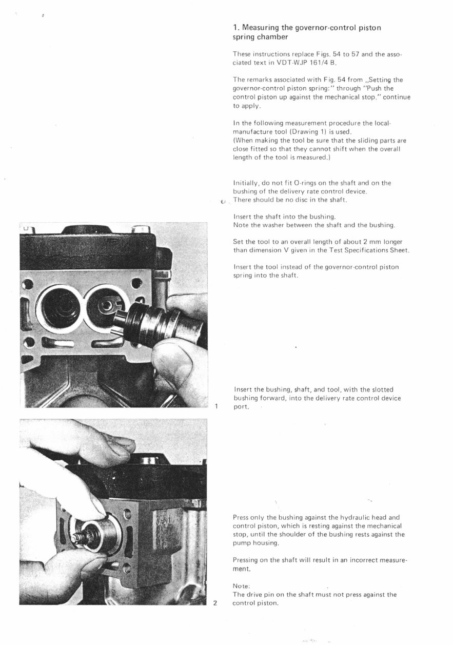
Insert the bushing, shaft, and tool, with the slotted
bushing forward, into the delivery rate control device
port,
Press only the bushing against the hydraulic head and
control piston, which is resting against the mechanical
stop, until the shoulder of the bushing rests against the
pump housing.
Pressing on the shaft will result in an incorrect measure-
ment.
Note:
The drive pin on the shaft must not press against the
2 control piston.
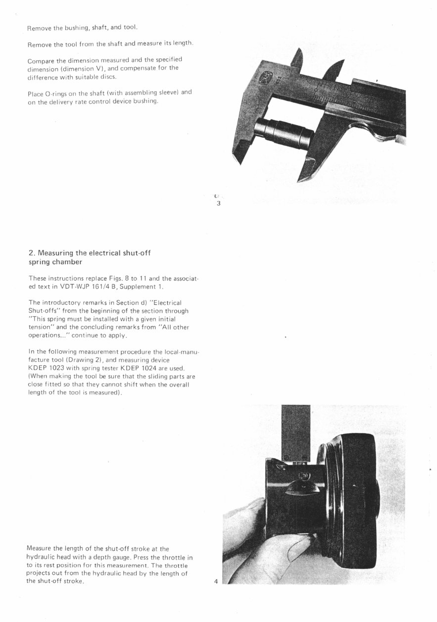
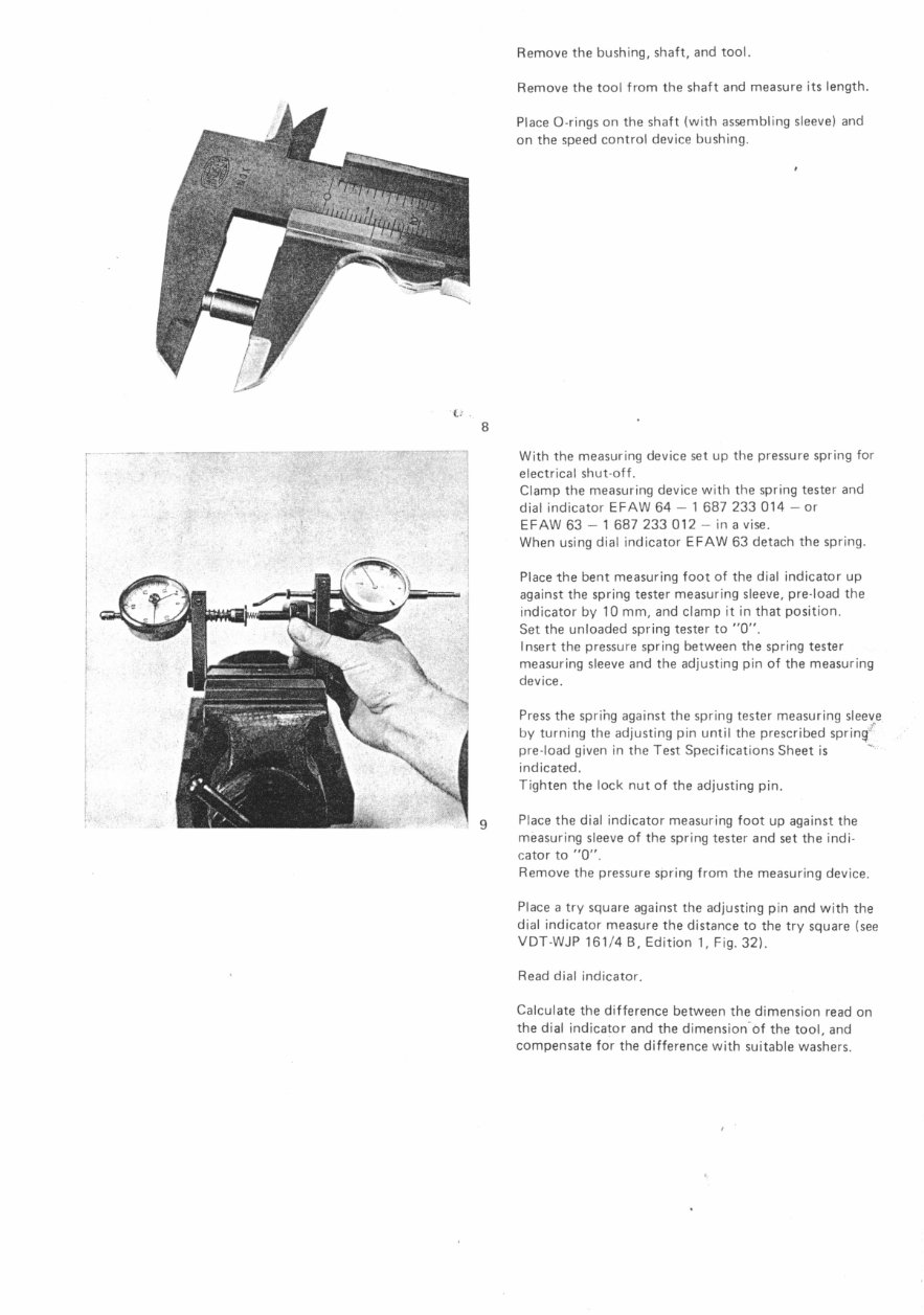
Remove the bushing, shaft, and tool.
Remove the tool from the shaft and measure its length.
Compare the dimension measured and the specified
dimension (dimension V), and compensate for the
difference with suitable discs.
Place 0-rings on the shaft (with assembling sleeve) and
on the delivery rate control device bushing.
2. Measuring the electrical shut-off
spring chamber
These instructions replace Figs. 8 to 11 and the associat-
ed text in VDT-WJP 161/4 B, Supplement 1.
The introductory remarks in Section d) "Electrical
Shut-offs" from the beginning of the section through
"This spring must be installed with a given initial
tension" and the concluding remarks from "All other
operations..." continue to apply.
In the following measurement procedure the local-manu-
facture tool (Drawing 2), and measuring device
KDEP 1023 with spring tester K DEP 1024 are used.
(When making the tool be sure that the sliding parts are
close fitted so that they cannot shift when the overall
length of the tool is measured).
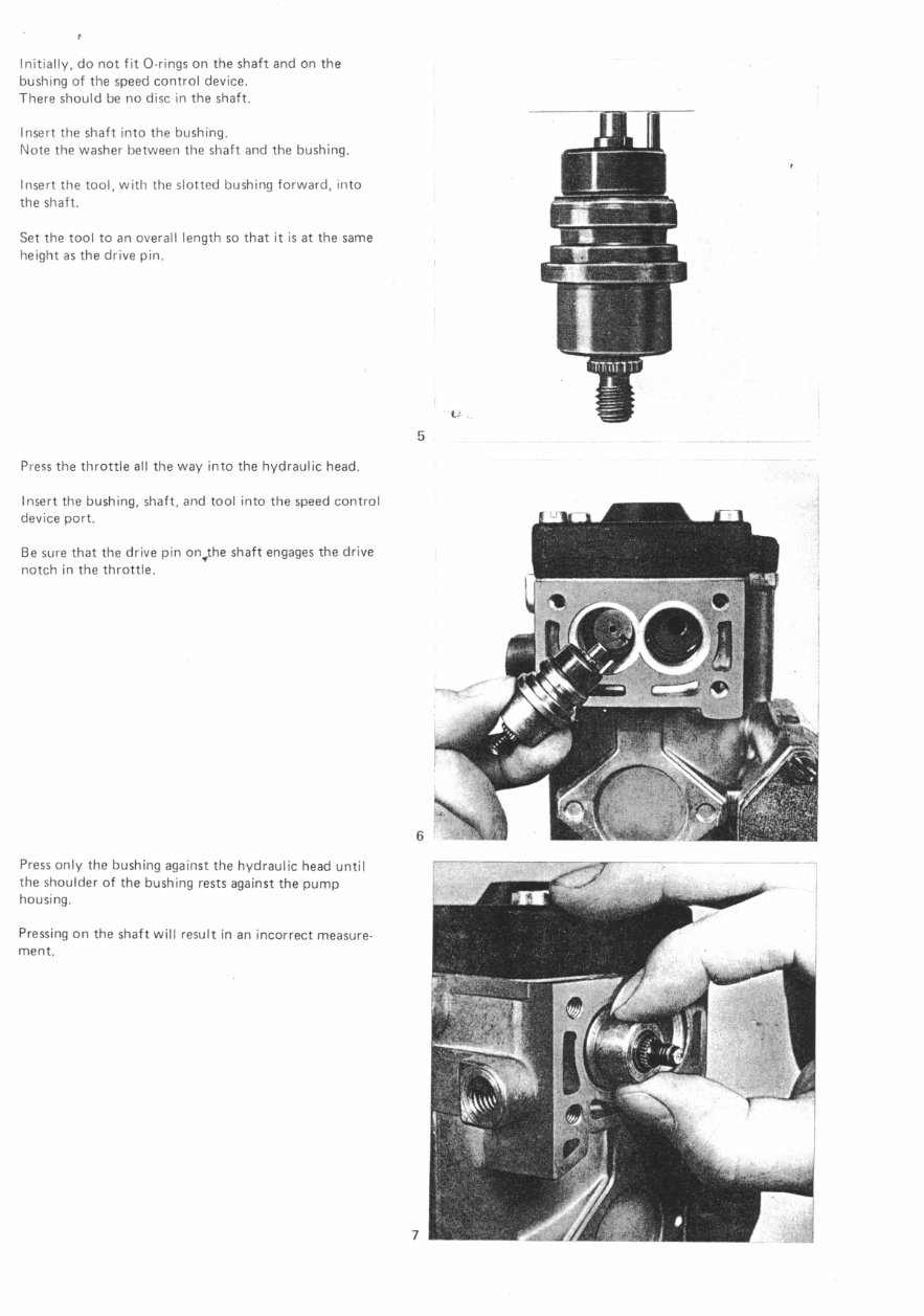
Measure the length of the shut-off stroke at the
hydraulic head with a depth gauge. Press the throttle in
to its rest position for this measurement. The throttle
projects out from the hydraulic head by the length of
the shut-off stroke.
Initially, do not fit 0-rings on the shaft and on the
bushing of the speed control device.
There should be no disc in the shaft,
Insert the shaft into the bushing.
Note the washer between the shaft and the bushing.
Insert the tool, with the slotted bushing forward, into
the shaft.
Set the tool to an overall length so that it is at the same
height as the drive pin.
5
Press the throttle all the way into the hydraulic head,
Insert the bushing, shaft, and tool into the speed control
device port.
Be sure that the drive pin on,the shaft engages the drive
notch in the throttle.
Press only the bushing against the hydraulic head until
the shoulder of the bushing rests against the pump
housing.
Pressing on the shaft will result in an incorrect measure-
ment.
Remove the bushing, shaft, and tool.
Remove the tool from the shaft and measure its length.
Place 0-rings on the shaft (with assembling sleeve) and
on the speed control device bushing.
With the measuring device set up the pressure spring for
electrical shut-off.
Clamp the measuring device with the spring tester and
dial indicator EFAVV 64 — 1 687 233 014 — or
EFAW 63 — 1 687 233 012 — in a vise.
When using dial indicator EFAW 63 detach the spring.
Place the bent measuring foot of the dial indicator up
against the spring tester measuring sleeve, pre-load the
indicator by 10 mm, and clamp it in that position.
Set the unloaded spring tester to "0".
Insert the pressure spring between the spring tester
measuring sleeve and the adjusting pin of the measuring
device.
Press the spring against the spring tester measuring sleeve
by turning the adjusting pin until the prescribed sprin4':
pre-load given in the Test Specifications Sheet is
indicated.
Tighten the lock nut of the adjusting pin.
Place the dial indicator measuring foot up against the
measuring sleeve of the spring tester and set the indi-
cator to "0".
Remove the pressure spring from the measuring device.
Place a try square against the adjusting pin and with the
dial indicator measure the distance to the try square (see
VDT-WJP 161/4 B, Edition 1, Fig. 32).
Read dial indicator.
Calculate the difference between the dimension read on
the dial indicator and the dimension of the tool, and
compensate for the difference with suitable washers.
Lc)
co
N
3
--- —OP.—
0,5
20--0—
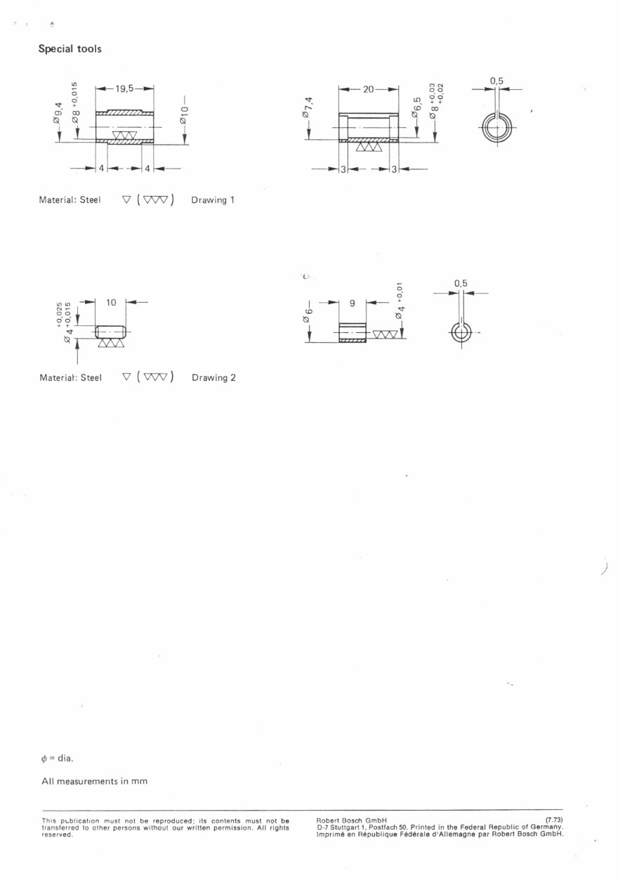
Special tools
Material: Steel V ( \777 ) Drawing 1
0,5
Materiak Steel V ( VW ) Drawing 2
(/) = dia.
All measurements in mm
This publication must not be reproduced: its contents must not be
transferred to other persons without our written permission. All rights
reserved.
Robert Bosch GmbH (7.73)
D-7 Stuttgart 1, Postfach 50. Printed in the Federal Republic of Germany.
Imprime en Republique Federale d'Allemagne par Robert Bosch GmbH.
You're Reading a Preview
What's Included?
Fast Download Speeds
Online & Offline Access
Access PDF Contents & Bookmarks
Full Search Facility
Print one or all pages of your manual
$31.99
Viewed 90 Times Today


Secure transaction
What's Included?
Fast Download Speeds
Online & Offline Access
Access PDF Contents & Bookmarks
Full Search Facility
Print one or all pages of your manual
$31.99
This manual provides repair instructions for the Cav Sims Bosch Distributor-Type Fuel Injection Pump EP/VA. It is also known as the Bosch 46 VDT - WJP 161/4 B Suppl. 3, Ed. 1. The manual includes a simplified method for measuring the spring chambers of the governor-control piston spring and the electrical shut-off spring. It covers the following:
- Measuring the governor-control piston spring chamber.
- Measuring the electrical shut-off spring chamber.
This manual consists of 10 pages with photo illustrations, making it very useful for the Garage Library. It is designed for both professional mechanics and DIY enthusiasts who require detailed repair instructions for the specified fuel injection pump.


