

Bosch Type P Testing Fuel Pump Testing manual
What's Included?
Fast Download Speeds
Online & Offline Access
Access PDF Contents & Bookmarks
Full Search Facility
Print one or all pages of your manual
.6-
0
BOSCH
TEST INSTRUCTIONS Ep
VDT — WPP 115/1 B
Edition 1.69 replaces 12.65
Translation of German edition of 10.63
Testing INJECTION PUMPS SIZE
P
4144).
ki 1 Ir.'
\
t
s s io
n
A l l
rig hts re,
-la-
it \ -- .•
Ii
_c
;T,
II
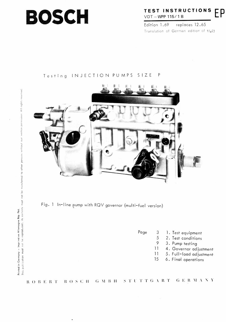
Fig. 1 In-line pump with RQV governor (multi-fuel version)
LL -E
ci. 8
„
a, -=
Page 3
1. Test equipment
5 2. Test conditions
9 3. Pump testing
11
4. Governor adjustment
11
5. Full-load adjustment
15
6. Final operations
It 0 B E B () (; II G NI I; II ITG ■ R G R NI \ 1
2
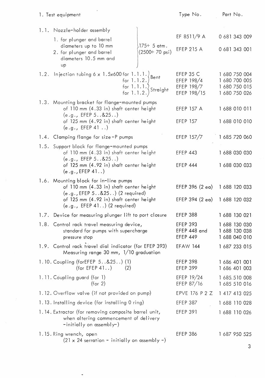
1. Test equipment
1.1. Nozzle-holder assembly
1. for plunger and barrel
diameters up to 10 mm 175+ 5 atm.
2. for plunger and barrel (2500+ 70 psi)
diameters 10.5 mm and
up
1.2. Injection tubing 6x 1.5x600 for 1.1.1.
for 1.1.2.
for 1. 1. 1.
for 1.1.2.
1.3. Mounting bracket for flange-mounted pumps
of 110 mm (4.33 in) shaft center height
(e .g EFEP 5 ..&25 ..)
of 125 mm (4.92 in) shaft center height
(e.g., EFEP 41 ..)
1.4. Clamping flange for size -P pumps
1.5. Support block for flange-mounted pumps
of 110 mm (4.33 in) shaft center height
(e.g., EFEP 5..&25..)
of 125 mm (4.92 in) shaft center height
(e.g.,EFEP 41..)
1.6. Mounting block for in-line pumps
of 110 mm (4.33 in) shaft center height
(e .g , EFEP 5. .&25. .) (2 required)
of 125 mm (4.92 in) shaft center height
(e.g., EFEP 41..) (2 required)
1.7. Device for measuring plunger lift to port closure
1.8. Control rack travel measuring device,
standard for pumps with supercharge
pressure stop
1.9. Control rack ;ravel dial indicator (for EFEP 393)
Measuring range 30 mm, 1/10 graduation
1.10. Coupling (forEFEP 5. .&25 ..) (1)
(for EFEP 41..) (2)
1.11. Coupling guard (for 1)
(for 2)
1.12. Overflow valve (if not provided on pump)
1.13. Installing device (for installing 0 ring)
1.14. Extractor (for removing composite barrel unit,
when altering commencement of delivery
-initially on assembly-)
1.15. Ring wrench, open
(21 x 24 serration - initially on assembly -)
Bent
Straight
Type No. Part No.
EF 8511/9 A 0 681 343 009
EFEP 215 A 0 681 343 001
EFEP 35 C 1 680 750 004
EFEP 198/4 1 680 700 005
EFEP 198/7 1 680 750 015
EFEP 198/15 1 680 750 026
EFEP 157 A 1 688 010 011
EFEP 157 1 688 010 010
EFEP 157/7 1 685 720 060
EFEP 443 1 688 030 030
EFEP 444 1 688 030 033
EFEP 396 (2 ea) 1 688 120 033
EFEP 394 (2 ea) 1 688 120 032
EFEP 388 1 688 130 021
EFEP 393 1 688 130 030
EFEP 448 and 1 688 130 038
EFEP 449 1 688 040 010
EFAW 144 1 687 233 015
EFEP 398 1 686 401 001
EFEP 399 1 686 401 003
EFEP 19/24 1 685.510 008
EFEP 87/16 1 685 510 016
EPVE 176 P 2 Z 1 417 413 025
EFEP 387 1 688 110 028
EFEP 391
1 688 110 026
EFEP 386 1 687 950 525
3
4
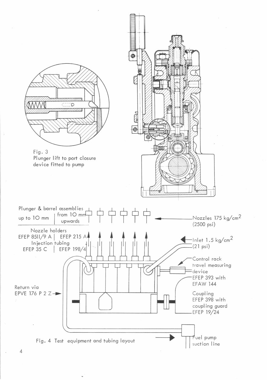
Fig. 3
Plunger lift to port closure
device fitted to pump
Plunger & barrel assemblies y
from 10 mrri 1
up to 10 mm
upwards
Nozzle holders
EFEP 8511/9 A EFEP 215 Alf
Injection tubing
EFEP 35 C 1 EFEP 198/4
Return via
EPVE 176 P2 Z
n fl
Fig. 4 Test equipment and tubing layout
J uel pump
suction line
1— I nlet 1.5 kg/cm 2
(21 psi)
"
-- Control rack
travel measuring
device
- EFEP 393 with
EFAW 144
Coupling
EFEP 398 with
coupling guard
EFEP 19/24
HI-
No m
Nozzles 175 kg/cm 2
(2500 psi)
L_1 L_1 L_I LJ
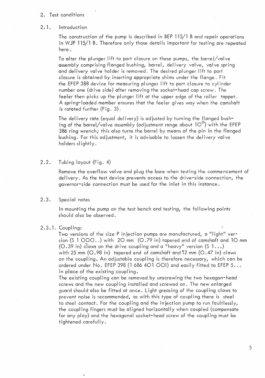
2. Test conditions
2. 1 . Introduction
The construction of the pump is described in BEP 115/1 B and repair operations
in WJP 115/1 B. Therefore only those details important for testing are repeated
here
To alter the plunger lift to port closure on these pumps, the barrel/valve
assembly comprising flanged bushing, barrel, delivery valve, valve spring
and delivery valve holder is removed. The desired plunger lift to port
closure is obtained by inserting appropriate shims under the flange. Fit
the EFEP 388 device for measuring plunger lift to port closure to cylinder
number one (drive side) after removing the socket-head cap screw. The
feeler then picks up the plunger lift at the upper edge of the roller tappet.
A spring-loaded member ensures that the feeler gives way when the camshaft
is rotated further (Fig. 3).
The delivery rate (equal delivery) is adjusted by turning the flanged bush-
ing of the barrel/valve assembly (adjustment range about 10
0
) with the EFEP
386 ring wrench; this also turns the barrel by means of the pin in the flanged
bushing. For this adjustment, it is advisable to loosen the delivery valve
holders slightly.
2.2. Tubing layout (Fig. 4)
Remove the overflow valve and plug the bore when testing the commencement of
delivery. As the test device prevents access to the drive-side connection, the
governor-side connection must be used for the inlet in this instance.
2.3. Special notes
In mounting the pump on the test bench and testing, the following points
should also be observed.
2 3.1. Couplingg
Two versions of the size P injection pumps are manufactured, a "light" ver-
sion (S 1 000..) with 20 mm (0.79 in) tapered end of camshaft and 10 mm
(0.39 in) claws on the drive coupling and a "heavy" version (S 1...)
with 25 mm (0.98 in) tapered end of camshaft and 12 mm (0.47 in) claws
on the coupling. An adjustable coupling is therefore necessary, which can be
ordered under No. EFEP 398 (1 686 401 001) and easily fitted to EFEP 5...
in place of the existing coupling.
The existing coupling can be removed by unscrewing the two hexagon-head
screws and the new coupling installed and screwed on. The new enlarged
guard should also be fitted at once. Light greasing of the coupling claws to
prevent noise is recommended, as with this type of coupling there is steel
to steel contact. For the coupling and the injection pump to run faultlessly,
the coupling fingers must be aligned horizontally when coupled (compensate
for any play) and the hexagonal socket-head screw of the coupling must be
tightened carefully.
5
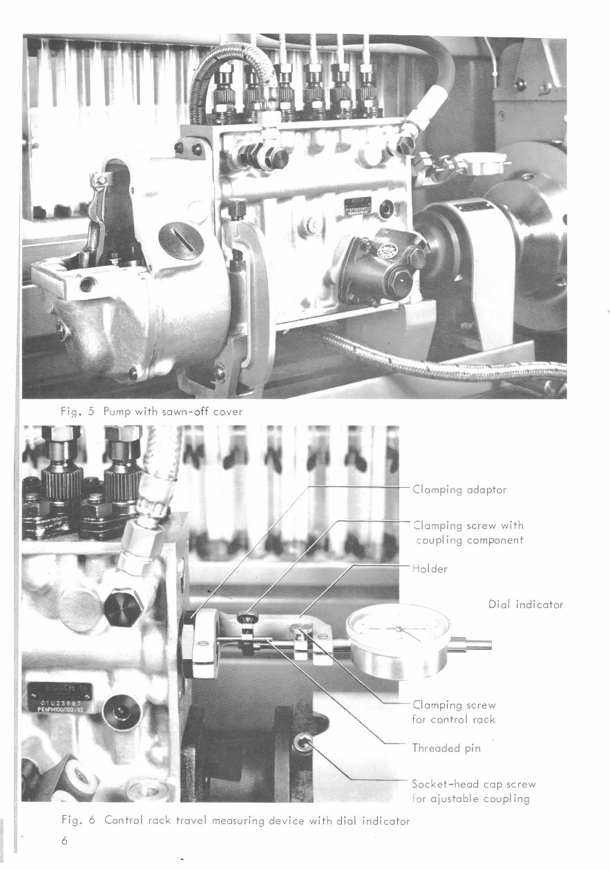
Fig. 5 Pump with sawn-off cover
FrA
1
Clamping adaptor
Clamping screw with
coupling component
Dial indicator
Clamping screw
for control rack
Threaded pin
Socket-head cap screw
For *stable coupling
Fig. 6 Control rack travel measuring device with dial indicator
6
2.3.2. Overflow valves!
The suction-chamber flushing specified for testing P-pumps necessitates the
use of an overflow valve. EPVE 176 P2 Z is stipulated for this purpose which
already exists on some of the pumps. The EPVE 219 P 2 Z fitted to the PE 6 PM..
S 2 pump can also be used.
However, overflow valves must be removed and the inlet line connected in
their place for testing the commencement of delivery, as the inlet must be dis-
connected from the drive side due to lack of space. For the PE 6 PM. .S 2
pump, the EF 8456/16 reducing adaptor is required for this purpose.
2.3.3. Mounting:
When flange-mounted pumps are fixed to bracket EFEP 157 A or 157 with
clamping flange EFEP 157/7, the support bracket EFEP 443 or 444 supplied is
to be placed underneath and bolted to the extra fixing holes at the governor end
to prevent undesirable vibrations caused by the length and the weight of the
6-cylinder pumps.
For base-mounted pumps, clamping supports with one-sided "C" clamps have
been produced which clamp the pump on alternate sides; see that the bore for
measuring plunger lift to port closure remains accessible, i.e., that the front
"C" clamp is on the opposite side of the pump.
2 3.4. Lubrication:
P-size injection pumps in their "heavy version" (S 1 ...) have a plain bearing
as intermediate bearing. Attention must therefore be paid in lubricating, as
is the case with the light versions on account of the lubrication of the tappet
rollers. For the basic setting of the pump, the fitting of a provisional gover-
nor cover sawn off as shown in Fig. 5 for these purposes is recommended. In
the case of a flange-mounted pump, the bores in the flange-side bearing cover
should also be properly sealed.
2.3.5. Control rack travel measuring device:
To obtain the basic setting for the injection pump and to test the centrifugal
governor, the EFEP 393 control rack travel measuring device used in con-
junction with the EFAW 144 dial indicator (measuring range 30 mm, 1/10
graduation) was devised. The following sequence of steps is recommended in
fitting it.
1. Remove protection cap
2. Screw threaded pin (M 2.3) into the control rack
3. Screw in the clamping adaptor
4. Fit holder
5. Insert the dial indicator and screw coupling component on to dial
indicator spindle
6. With the control rack in the STOP position, set the dial indicator to zero
and clamp on the coupling component tight. Ensure that the control rack
can travel the full distance (approx. 21 mm) (Fig. 6).
For the different method of fitting in the case of pumps with a full-load stop
governed by supercharge pressure, see Page 14.
7
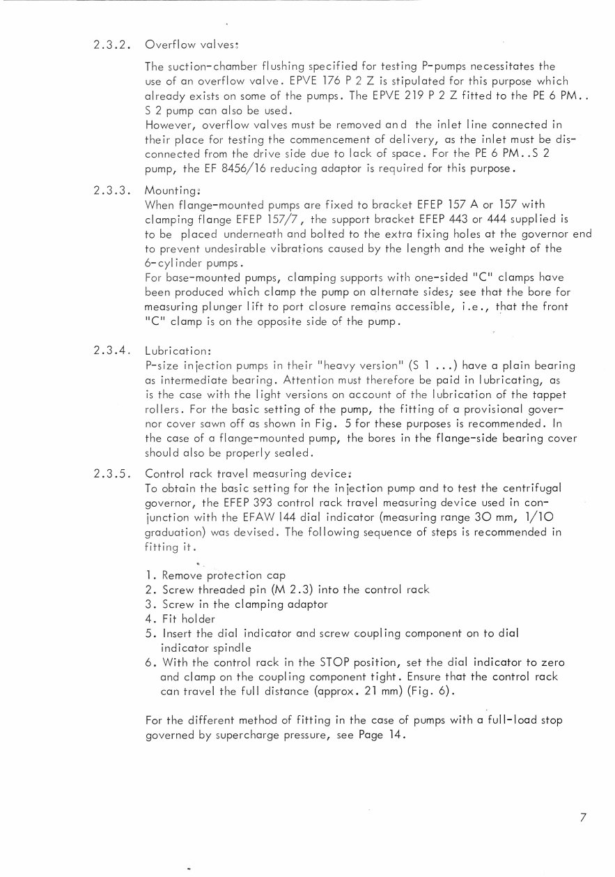
Fig. 7 Removal of the barrel / valve assembly
Fig. 8 Exchanging
the EPPT 47 P 7 ... 13 X shims
8
3. Pump testing
3.1. Setting the commencement of delivery (Figs. 7 and 8)
The "plunger lift to port closure, ... mm from B.D.C." is the lift of the plun-
ger from bottom dead center until delivery commences, i.e., until the rising
plunger just covers the inlet port and test oil ceases to flow at the overflow
pipe.
Mount the pump, remove top cover, set test-bench selector lever to position
for testing commencement of delivery and connect up the tubings. Disconnect
the governor of pumps with governor, i.e., remove the governor cover. Fit
the EFEP 393 control rack travel measuring device with dial indicator 144
and adjust to zero with the control rack in the STOP position. Then adjust
control rack to travel specified in Test Specifications for equal delivery test,
unless a special rack setting is specified for the plunger lift to port closure
measurement. With cylinder 1 (drive side) in the B.D. C. position -roller
tappet is visible after removing the hexagonal socket-head screw - screw in
device EFEP 388 without gasket, lift the measuring spindle and set dial indi-
cator to zero with cam in the B.D.C. position.
3.1.1. Setting plunger lift to port closure:
Rotate camshaft (in direction of rotation shown on type plate) until the dial
indicator shows the measurement specified for plunger lift to port closure.
Set the graduated-disc pointer to a convenient number for measurement.
3.1.2. Checking commencement of delivery:
Unscrew bleed screw on the nozzle holder, set test-bench selector lever to
position for testing commencement of delivery (if necessary, increase pres-
sure at the adjustable relief valve) and again rotate camshaft from B.D.C.
until delivery commences: the graduated-disc pointer must indicate the same
reading as before.
3.1.3. Checking the cam phasing:
The commencement of delivery for the other plunger and barrel assemblies
is similarly set relative to the barrel tested according to the cam phasing in-
tervals.
for 4-cylinder units 90
0
intervals
Tol. ± 0.5 °
for 6-cylinder units 60 ° intervals
etc.
Abnormal phasing intervals are given on the Test Specifications.
If the checks do not produce the figures stipulated, the EPPT 47 P 7..13 X
shims under the flanged bushings must be exchanged. If delivery commen-
ces too early, add further shims; if it is too late, remove shims (Figs. 7 and 8).
Use EFEP 391 to extract the barrel/valve assembly and EFEP 387 to install the
0 rings when replacing. Special attention should be paid to the 0 rings when
re-assembling. It is recommended to set the slots of the flanges in the center
during assembly (for delivery rate adjustment).
9
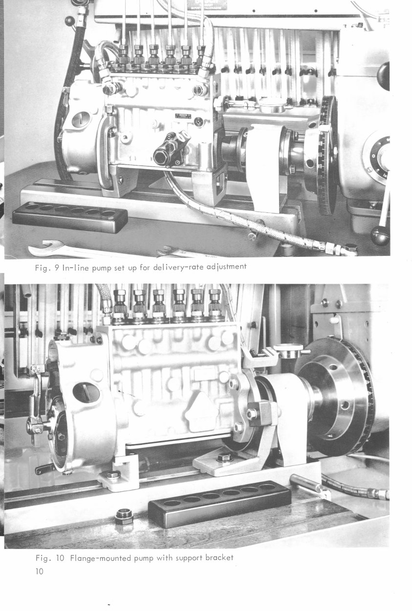
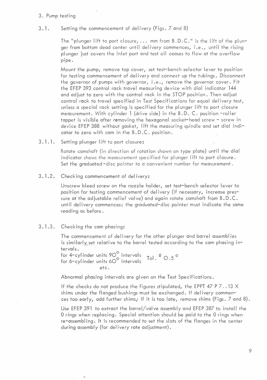
Fig. 9 In-line pump set up for delivery-rate adjustment
Fig. 10 Flange-mounted pump with support bracket
10
You're Reading a Preview
What's Included?
Fast Download Speeds
Online & Offline Access
Access PDF Contents & Bookmarks
Full Search Facility
Print one or all pages of your manual
$31.99
Viewed 52 Times Today


Secure transaction
What's Included?
Fast Download Speeds
Online & Offline Access
Access PDF Contents & Bookmarks
Full Search Facility
Print one or all pages of your manual
$31.99
Bosch Type P Testing Fuel Pump Testing manual
In-line pump with RQV governor (multi-fuel version)
Covers
- Test equipment
- Test conditions
- Pump testing
- Governor adjustment
- Full-load adjustment
- Final operations


