Mikuni Throttle Valves Carburetor Complete Workshop Service Repair Manual
What's Included?
Lifetime Access
Fast Download Speeds
Online & Offline Access
Access PDF Contents & Bookmarks
Full Search Facility
Print one or all pages of your manual
4th - Edition TTLE VAL \
- ----- - - - - - IllbOduclion Sudco International IS America's leading source for Mikuni aftermarket carburetors, parts, accessories, and information. Sudco has been selling Mikuni products to the powersports industry for over twenty five years and continues to provide the most comprehensive service available for Mikuni aftermarket products. The Sudco / Mikunj tuning manual is a compilation of official Mikuni techuical manuals combined with years of hands on experience setting up, tunjng, and troubleshooting Mikuni products. All information contained within this manual is specific to Mikuni aftennarket carburetor designs only. The Milami aftermarket division does not represent the exact Mikuni products which may have been supplied by the Original Equipment Manufacturer. In most cases, the parts from aftermarket carb designs are not inter- changeable with OEM carburetors. Please take the time to read the chapter on general carburetor theory and operation. Sudco has o~n been called upon to troubleshoot carburetor pr9blems. Many types of problems can be identi. fied and solved with an understanding of carburetor fuddamentals. Motorcycle perfonnance does not have to be compljcated if you have the basic knowledge. It is our hope that you will use this mauual as a guide and reference tool as do many schools and race mechanics. ! ,.,_ .. ,e
1I81E 01 CONIENTS Basic slide carburetor theory and operation. General Mikuni carburetor circuitry and tuning for motorcycle applications. Ttoubleshooting, general procedures, and techniques to determine rich from lean. Carburetbr synchronization - VM Smoothbores, RS and others. Carburetors and related parts charts A. ~Roundslide B. Throttle Valves C. VM29 Smoothbore D. VM33 Smoothbore E. TM Flatslide F. TMX Flatslide G. TM33 Flatslide H. HS40 (TM40) Flatslide 1. HSR42J45J48 Smoothbore J. RS Smoothbore General Mikuni tuning parts - motorcycle carbs A. Main & Pilot Jets B. Needle Jets C. Jet Needles D. Ma nifolds and Adapters E. Fuel Pumps F. Carburetor Accessories G. Carb Kits H. Pingel Products I. K&N Filters & Flame Arresters Watercraft Carburetors Tools Reading Spark Plugs ~ 2 3 9 13 15 - 57 15-23 24-25 26-27 28~29 30-33 34-38 39 40-44 45-52 53-57 58-70 58-59 60 .. 62 63-1'0 71 72 73 74 75 76-77 78-90 91 92 1
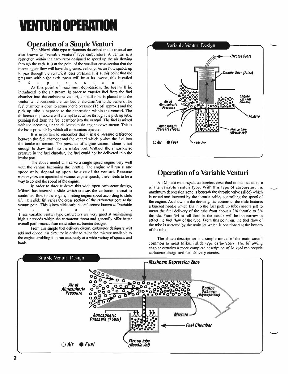
2 VENlURIOPBUDlON Operation of a Simple Venturi The Mikuni slide type carburetors descrihed in this manual are also known as "variable venluri" type carburetors. A venturi is a restriction within the carburelor designed to speed up the air flowing through Ihe carbo It is al the poinl of the smaJ. lcst cross section thai the incoming air flow will have thc greatesl velocity. As air /low spe.xls up 10 pass thmugh the venturi, il loses pressure. It is at this poinl that the pressure within the carb thIoa! will be at its lowest; this is called "d cpr e s s ion" At Ihis point of maximum depression. the fuel will be introduced 10 the air stream. ID order to transfer fuel from the fuel chamber inlo the carburelor venturi, a small tube is placed into the venturi which connects the fuel load in the chamber 10 dle venturi. The fue! chamber is open 10 atmospheric pressure (J 5 psi approx.) and the pick up rube is exposed 10 the depression within thc vennui. The differeoce ill pressure will attempt to equalize through Lhe pick up tube, pushing fuel from the fuel chamber into the venturi. The fuel is mixed with the incoming air and delivered to the engine down stream. This is the basic principle by which all carburelors opera Ie. It is important to remember thai it is the pressurc difference between thc fuel chambe( and the venturi which pushes the fuel into the intake air slream. The presence of engine vacuum a!one is not enough to draw fuel into the intake pon. Wilhout thc atmospheric pressure in thc fuel chamber, the fuel could not be delivered into the inlake pon. The above model will serve a single speed engine very weI! with the .venturi becoming Ihe throttle. The engine will run alone speed only, dcpending upon Ihe size of Ihe venturi. Because motorcycles are operated al various engine speeds, there needs 10 be a way 10 conb"ol the speed of the engine. In order to throttle dow'1) this wide open carburetor design, Mikuni has inserted a slide which crosses the carburetor throat to conb"ol air flow to the engine, limiting engine speed according 10 slide lift . This slide lift varies the cross section of the carburetor bore III the venturi painl llJ.is is how slide carburetors become known as dvariable ve n I uri ., These variable ventwi type carburetors are very good at maintaining high air speeds within the carburetor throal and generally olIer better overall perfonnancc than most other carburelor designs. From this simple fuel delivery circuit, carburetor designers will add and divide this circuitry in oruer 10 tailor the mixture available to the engjne, enabling it 10 run aCCUr.llely at a wide variety of speeds and loads. Air ~t Atmospht:rJ, Pressure I Almaspht:rJ, Pressure (15fJ$/) o Air • FilS! AIm/)$fJhl'" Pre$slIre ( 6Psl) o AIr .FIJel Operation of a Variable Venturi MixltJrf All Mikuni motorcycle carburelors described in tbis manual are of the variable venturi type. With Ihis Iype of carburelor, the maximum depression zone is beneath the throttle valve (slide) which is raised and lowered by the Ihrollie cable, conrrolling the speed of the engine. As shown in the drawing, Ibe bOllom of the slide features a tapered needle which fits into tbe fuel pick up tube (needle jet) 10 meter the fuel delivery of the tube from about a 1/4 throttle to 3/4 throttle. From 3/4 to full lhrollle, the needle will be 100 narrow to affeCI (he fuel flow of the tube. From this point on, the fuel now of the rube is metered by the main jel which is positioned at the bonom of the tube. The above description is a simple model of the main circuil common 10 most Mjkuni slide type carburetors, Tile following chapter contains a more complete descriplion of Mikuni motorcycle carburelor design and fuel delivery circuits. M~Jmum Depression lDne ..... 1---- fuel Chlmbet
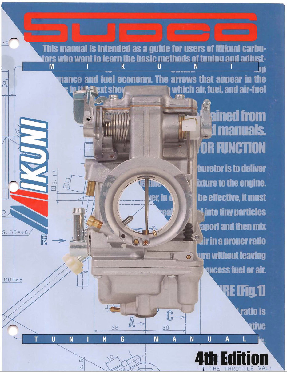
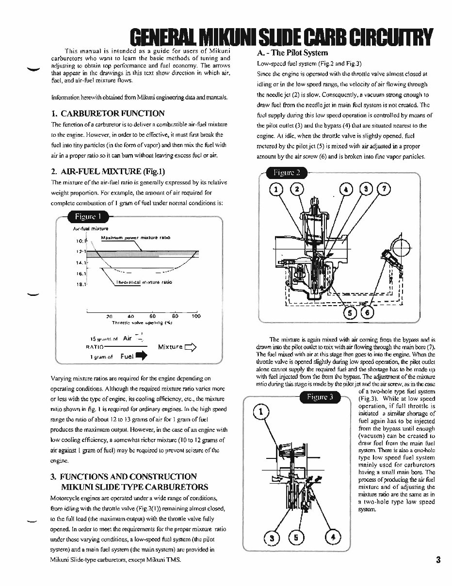
- GENERAl. MIKUNI SUDE CARB CIRCURRY This manual is intended as a guide for users of Mikuni carburetors who want to learn the basic methods of tuning and adjusting to obtain top performance and fuel economy. The aJTOWS that appear in the drawings in this tcxt show direction in which air, fuel, and air-fuel mixrure flows. [nfonnation herewith obtained from Mikuni engineering daJa and manuals. 1. CARBURETOR FUNCDON The function ofa carbUTetor is to deliver a combustible air-fuel mixture 10 the engine. However, in order to be effective, it must first break the fuel into !iny particles (in the form of vapor) and then mix the fuel with air in a proper ralio so il can bum without leaving excess fuel or air. 2_ AIR-FUEL MIXTURE (Fig.I) The mixture of the air-fuel ratio is generally expressed by its relative weight proportion. For example, the amounl of air required for compiete combustion of I gram of fuel under nonnal conditions is: A,(·fu6i mLllwro 14 .. 1 16.1 18.1 ' ,-~,~ .. -.--------------- .. ,~ 1I\ .. O,&I,C61 O"i),)((ure (11;0 -' 15 ~,~,J\< ,,1 Air .-: 100 RA TlO------- MixtureQ 1 9r~m of Fuel ~ Varying mixrure ratios are required for the engine depending on operating conditions. Although the required mixture rario varies more or less with the type of engine, its cooling efficiency, etc .. the mixture ratio shown in fig, I is required for ordinary engines. In the high speed range the ratio of about 12 to 13 grams of air for I gram of fuel produces the maximum output. However, in the case of an engine with low cooling efficiency, a somewhat richer mixture (10 to 12 grams of air against I gram of fuel) may be required to prevent seizure of the engine. 3. FUNCflONS AND CONSTRUCIlON MIKUNI SLIDE lYPE CARBURETORS Motorcycle engines are operated under a wide range of conditions, from idling with the throttle valve (Fig.2( I)) remaining almost elosed, to the full load (the maximum output) with the throttle valve fully opened. In order to meet the requirements for the proper mixrure ratio under these varying conditions, a low-speed fuel system (the pilol system) and a main fuel system (the main system) arc provided in Mikuni Slide-type carburetors, except Mikuni TMS. A. - The Pilot System Low-speed fuel system (Fig.2 and Fig.)) Since lhe engine is operated with the throttle valve almost closed at idling or in the low speed range, the velocity ofaiT flowing through the needle jet (2) is slow. Consequently, a vacuum strong enough to draw fuel from the needle jet in main fuel system is not created. The fuel supply during this low speed operation is controlled by means of the pilot outlet (3) aud the bypass (4) that arc situated nearest to the engine. At idle, when lhe throttle valve is slightly opened. fuel metered by the pilot jet (5) is mixed with air adjusted in a proper amount by the air screw (6) aud is broken into fme vapor panicles. I' ~ . 11 II ~-:.--;; -_.:-=~ J ~ -..:C!)---- j. The mixture is again mixed with air coming from the bypass and is drown into the pilot outlet to mix with air flowing through the main bore (7). The fuel mixed with air at this stage then goes 10 into the engine. When the thronle valve is opened slighLly during low speed operation. the pilot ouLiet alone cannot supply the required fuel and the shortage has to be made up with fuel injected from L1le from the bypass. The adjustment of the mixrure ratio during this stage is made by the pilot jet and the air screw. as in the case of a two-hole type fuel system (Fig.3). While lit low speed operation, if full throttle is initiated a similar shortage of fuel again has to be injected from me bypass until enough (vacuum) can be created to draw fuel from the main fuel system. There is also a one-hole type low speed fuel system mainly used for carburetors having a smaJJ main bore. TI'tC process of producing the air fuel mixture and of adjusting the mixture ratio are the same as in a two-hole type low speed system. 3
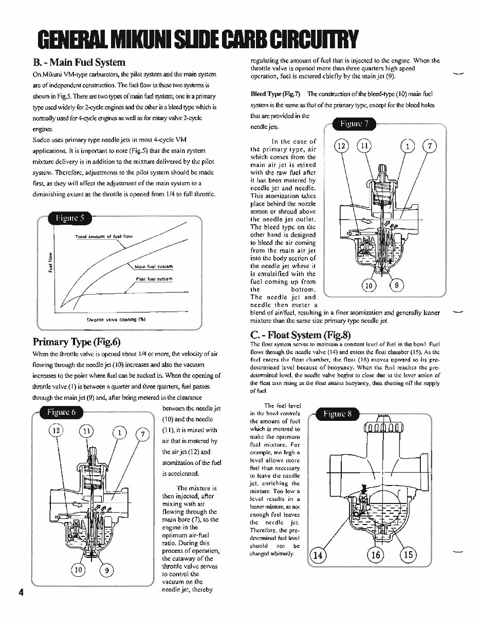
4 GENERAl. MIKUNI SUOE CARB CIRCURlY B. - Main Fuel System On Mikuni YM-type carburetors, the pilot sy&tem and the main system are of independent construction. TIle fild Oow in these two systems is shown in Figj. There are two types of main fuel system; one is a primary !)pC used widely for 2-cycle engines and the other is a bleed type which is nonnaUy used for 4-cycle engines !IS weU as for rotaIy valve 2-cycle engines. Sudeo uses primary type needle jets in most 4-cycle VM applications. [t is important to note (Fig.S) that the main system mixture delivery is in addition to the mixture delivered by the pilot system. Therefore, adjustments to the pilot system should be made first. as they will affect the adjustment of the main system to a diminishing extent as the throttle is opened from 114 to full throttlc. 10Iai amount 01 fuel flow Plio' fuel system Throttle valve ooenlllg t'lbl Primary Type (Fig.6) When the throttle valve is opened about 1/4 or more, the velocity of air flowing through the needle jet (10) increases and also the vacuum increases to the point where fuel can be sucked in. When the opening of throttle valve (I) is between a quarter and three quaners, fuel passes through the main jet (9) and, after being metered in the clearance between the needle jet (10) and the needle (J I), it is mixed with air that is metered by the air jet (12) and atomization of the fuel is accelerated. The mixrure is then injected, after mixing with air /lowing through the main bore (7), to the engine in the optimum air-fuel ratio. During this process of operation, the cutaway of the throttle valve serves 10 control the vacuum on the needle jet, thereby regulating the amount of fueltbat is injected to the engine. When the throttle valve is opened more than three quarters high speed operation, fuel is metered chiefly by the main jet (9). Bleed Type (Fig.7) The construction of the bleed-type (10) main fuel system is the same as trot of the pri.rnaJy type, except for the bleed holes that are provided in the need Ie jets. In the case of the primary type, air which comes from the main air jet is mixed with the raw fuel after it has been metered by needle jet and needle. nus atomization takes place behind the nozzle screen or shroud above the needle jet outlet. The bleed type 00 the other hand is designed to bleed the air coming from the main air jet into the body seclion of the needle jet where it is emu lsi (jed with the fuel coming up from the bollorn. The needle jet and needle then meter a blend of air/fuel, resulting in a finer atomization and generally leaner mixture than the same size primary type needle jet. C. - Float System (Fig.8) The float system serves to main lain a constant level of fuel in the bowl. Foci flows through tlte needle valve (14) and enters the float ebalDbcr (15). As the fu<!1 enters the float chamber, the floal (16) moves upward 10 ils pre- delemtined level because of buoyancy. When the fuel reaches the pre- detemlined level. the needle valve begins to close due to Ihe lever aClion of the float:mn rising as the float 3ltains buoyancy, thu:; shuning olTthe st.rpply of fuel. The fuel level in the bowl eonrrols the amount of fuel which is metered to makc the optimUl'l fuel mi;dure. For examplc, too high a level allow~ morc fuel than necess.ary 10 leave the needle jet. enrichillg the mixture. Too Iowa level resu Its in :I leaner mixture, as not enough fuel leaves the need Ie jet. Therefore, the pre- dctcnnincd fuel level should nOI be changed arbitrarily.
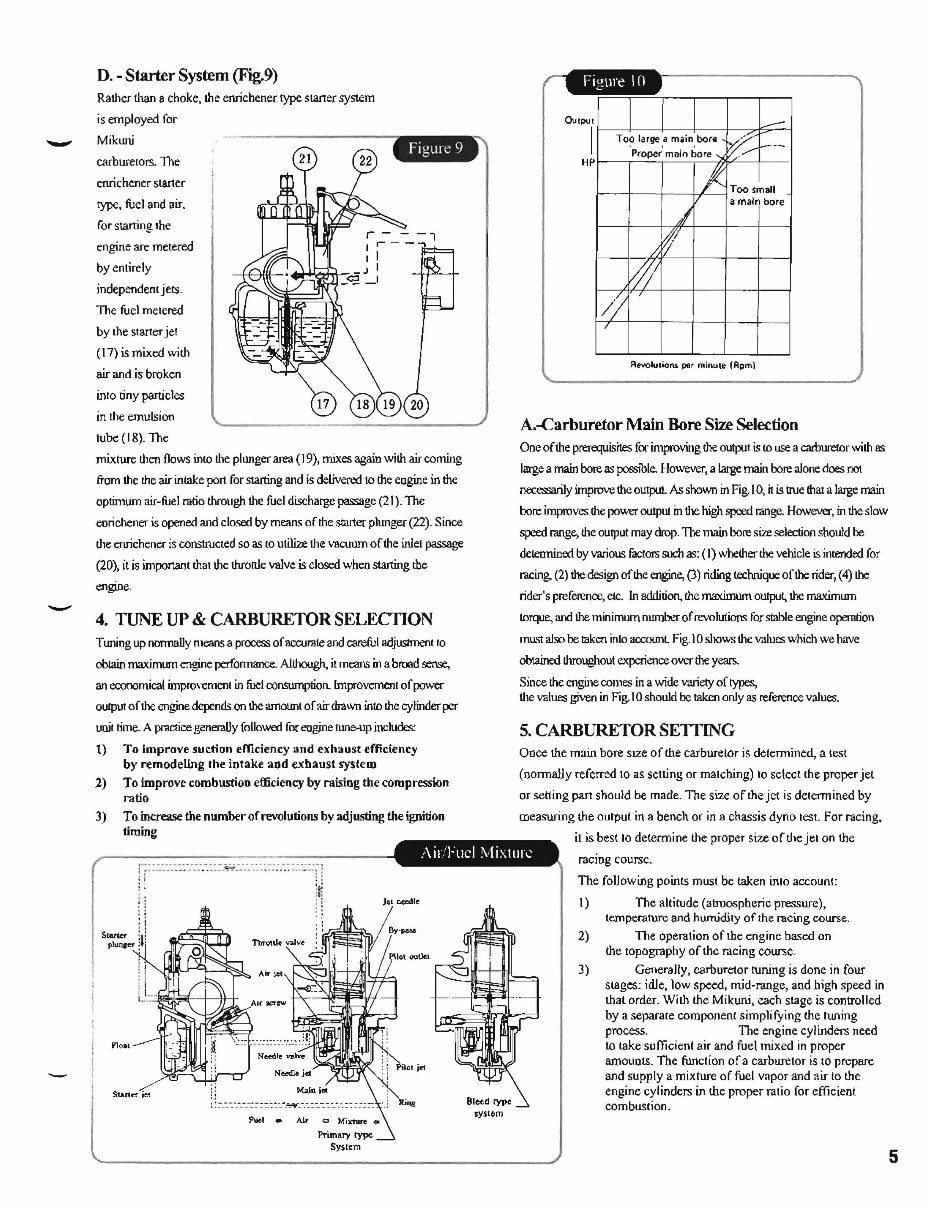
- - D. - Starter System (Fig.9) Ralher than 8 choke, the enrichener type staner system is employed. for Mikuni carburetors. The enrichenerstaner type, fuel and air. for starting the engine are metered byenlirely independent jets. The fuel melered by the starter jel (17) is mixed with air and is broken into tiny particles in Ihe emulsion tube (18). The mixture Ihen flows inlD the plunger area (19), mixes again with air coming from the the air intake port for starting and is delivem.:llo the eogine in the optimum air-fuel ratio through the fuel discharge passage (21) . ThE: eorichener is opened and closed by means of the starter phmger (22). Since Ihe enrichener is constructed so as to Ulilize the Vllcuum of the inlel passage (20), it is important thaI the throttle valve is closed when starting the engJJIe. 4. TUNE UP & CARBURETOR SELECTION T lUling up nonnaIJy means a process of IICCUrBte and careful adjuslmeot 10 obtain maximum engine performance. Although, it means in a broad sense, an economical improvement in fuel consumption. Improvement of power oulput of the engine depends on the amOWlt of air drawn into the cylinder per unil time. A practice generally followed for engine rune-up inchldes: 1) To improve suction efficiency and exhaust efficiency by remodeling the intake aod exhaust system Z) To improve combustion efficiency by raising the compression ratio 3) To increase the number of revolutiollli by adjusting the ignition timing Output I f------+----+--+-----+------::>-7--j HPr---r-~,---.-~~~~---1 Revolutions per m~rlUle (Apm) A.-Carburetor Main Bore Size Selection One of the prerequisites [or improving !he output is to use a carburetor with as large a main bore. as posstble. However, a large main bore alone does not nec=IDJy improve the output. As shown in Fig.J 0, it is \rue thal a large main bore improves the power output in dlC high speed range. However, in the slow speed range, the output may drop. TIle main bore size selection should be deletmined by variouc; fuctors such as: (I) whether the vehicle is intended for racing. (2) the design of the engine, (3) riding technique of the rider, (4) the rider's preference, etc. In addition, the maximum output, the maximum torque, and the minimum numb..'T of rcvolutionc; for stable engine operation must also be taken into accounL Fig. 1 0 shows the values which we h3Ve obtained throughout experience over the years. Since the engine comes in a wide variety of types., the values given in Fig. I0 should be taken only as reference values. 5. CARBURETOR SETTING Once the main bore SIZe oflhe carburetor is detennined, a lest (llonnaUy referred 10 as selting or matching) 10 select the proper jet or setting pan should be made. The size of the jet is determined by lDeaswing the output in a bench or in a chassis dyno lest. For racing. Air,Fuel MiXll11-: il is best 10 detennine the proper si7..e of the jel on the racing course. ri: =.:: -:.-.~: -::.-.-.-.: -: ~~ :~~:~ ~~::: :::: .: ~ :.::.::: -i i: ~ '. : . i: . ' : I Start<r !: PI_ .. :I: I· !l 1i :. '::' .::i " l!£IoJl.;;iI--1--1t+ ~ : : =- _ .. :~.-----::. ::::.::. -.'"=¥--.:.::.. -. :.:..-.-.:: : :.::: FUel • Al.r Jel ocrdte 81eed type systom The following points must be taken inlo account: I) The altitude (atmospheric pressure), lemperature and humidity of the racing course. 2) The opera lion of the eng inc based on the topography of the racing wurse. 3) Generally, carburetor tuning is done in four SLages: idle, low speed, mid-range, and high speed in thai order. With the Mikuni, each stage is controlled by a separare componenl simplifying the tuning process. The engine cylinders need to take sufficient air and fuel mixed in proper amOllots . The function of a carburelor is 10 prepare and supply a mixture of fuel vapor and air to the engine cyl inders in the proper ralio for efficient combustion. 5
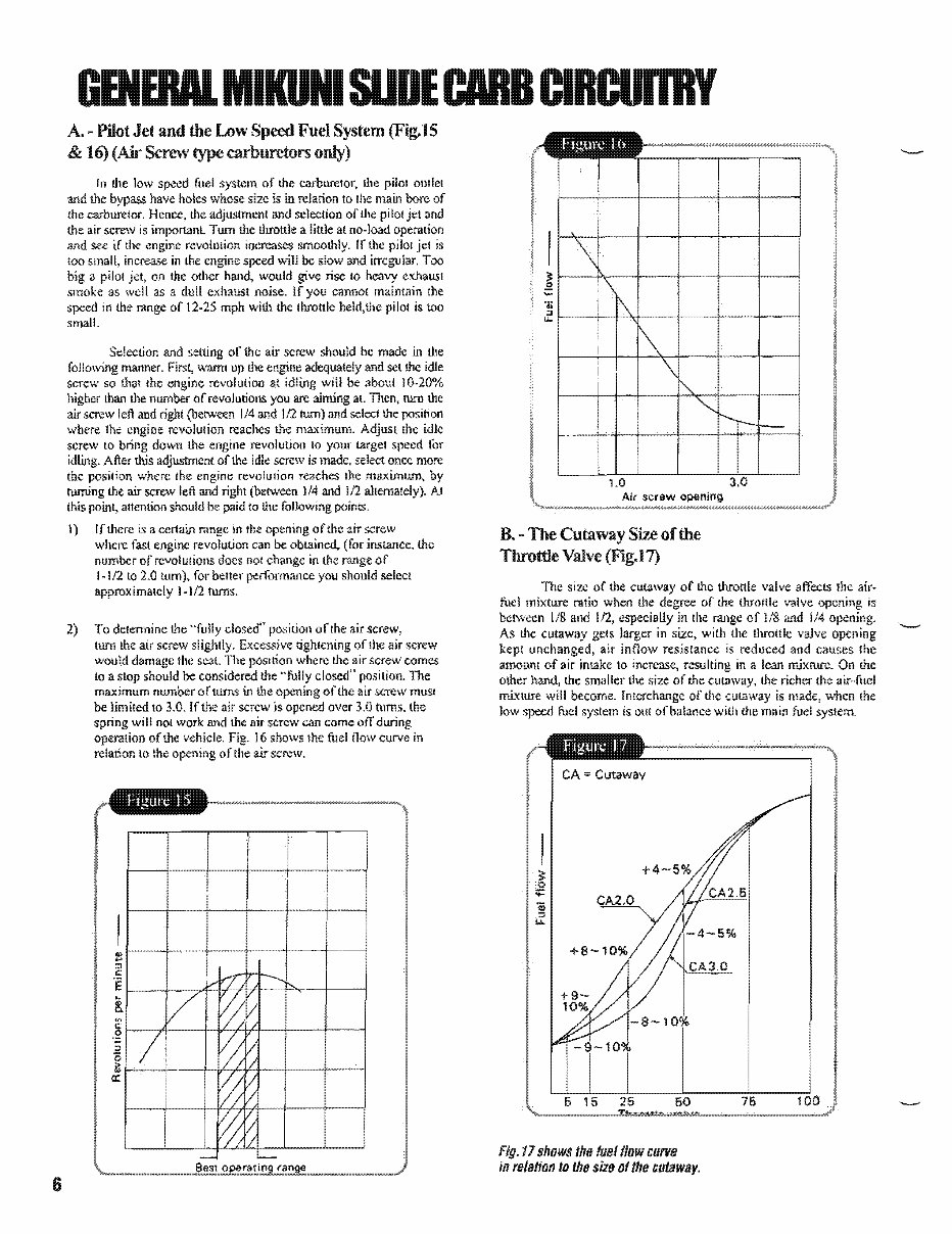
6 GENERAl CARB A. ~ Pilot Jet and the Low Speed Fuel & 16) (Air Screw type carburetors only) of the carburetor, the pHo! mulel size is in relation 10 Ihe main bore of the and selection of 11lC pi 10\ jet and Im,,,,n"l11 Tum the throttle a little at no-load operation and see if the revolution iocreases smoothly. if the pilot is too small, increase in the engine speed will be slow and irregular. a on the other hand, would give rise 10 heavy exhaust smoke as well as a dull exhauSI noise. If you cannol maintain the in the range of 12·25 mph with the throttle pilot is too small. Selection and of the air screw should be made in Ihe foJlowmg manner. warm up the adequately and set the idle screw so thai the revolutioQ at will be about 10-20% than 1l1C of revolutions you are aiming at. TIlen, rum the screw left and (between 1/4 and 1121um) and select the position wbere the revolution reaches the maximum. Adjust the idle screw to down the engine revolution 10 your targel for idling. After adjustment of the idle screw is made, select once more the position where tne engine revolution reaches the maximwn, turning the air screw left and right (bet'Ween 1/4 and 112 AI this poin!, attention should be paid to the following I) 2) of the air screw where fast can obtained, (for instance. the nwnber ofrevolulions does no! change in the range of 1-112 LO 2.0 for you should select 1-1/2 turns. To determine the "fully closed" position oflne air screw, tum the air screw slightly. Excessive tighlening of the air screw would damage the scal. TIle where the air screw comes 10 a Slop should be closed" The maximum nwnber of turns in the of the be limited 10 3.0. If the air screw is over 3.0 films,the spring will nol work and the air screw can come ofT during operation of the vehicle. 16 shows Ihe fuel now curve in relation 10 the a.tr screw. .e! :::J c: 'E 1- ....... ~f---Ac.r.,t~II----F"'-+---j & '" .g l--cA---+-Ij,L.,,4,4-+----+~____I :::J '0 i; I---~+----I- a:: 1.0 Air screw opening B. - The Cutaway of the Throttle (Fig.l7) The size of 1l1e cutaway of the t.hrottle valve affects Ihe air- fuel mixture ralio when the degree of the throttle valve is between 1/8 and 112, especially in the range of 118 and 1/4 UIJC;,,"'I!.. As lhe cutaway gelS in size, with the IllfOttie valve kepI unchanged, air resistance is reduced and causes amoUIlI of air intake 10 resulting in a lean mixture. On the olher hand, the smaller !lIe size of the cutaway, tlle richer the air-fuel mixture will become. of tllC cutaway is made, when Ine low speed fuel system is CUI of balance with the main fuel system. CA Cutaway Fig. 17 shows the fuelliow curve in relation to the size of the liULilIWlj!!f.
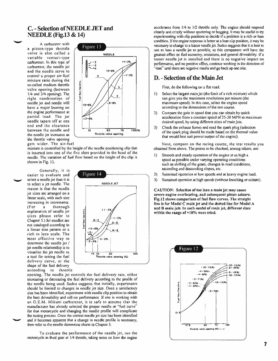
- C. - Selection of NEEDLE JET and NEEDLE (Fig.13 & 14) A carburetor with a piston-type tbroll Ie val ve is also called a variable venturi-type carburetor. In this type of carburetor, the needle jet and the needle serve to control a proper air- fuel mixture ratio during the so-called medium thtonk valve opening (between 1/4 and 3/4 opening). 11le rigbt combination of needle jet and needle will have a major bearing on the engine performance at partial load. The jet needle tapers off at one end and the clearance between the needle find . ... -3 ""L.J.4 ~ ~2 16 NHOLE 4 60 76 the needle jet increases as Throttle ""Ive op&ning the throttle valve opening gets wider . The air-fuel 1001%) mixture is controlled by the height of the needle positioning clip that is insened into one of the live slots provided in the head of the needle. The variation of fuel flow based on the height of the clip is shown in Fig. 13 . Generally, it is easier to evaluate and select a needle jet than it is to select a jet needle. The reason is that the needle jet sizes are arranged on a linear scale, with each size increasing in increments . (For a thorough explanation of needle jet sizes please refer to Chapter 5.) let needles are not cataloged according to a linear size pattern or a rich to lean scale. The most effective way to determine the needle jet / jet needle relationsbip is to visualize the jet needle as a tool for setting the fuel del i very curve, or the shape of the fuel deli very according to throllie NEEDLE JET 100 opening. The needlc jet controls the fuel delivery rate, either increasing or decreasing the fuel delivery according to the pro(i]e of tbe needle being used. Sudco suggests that initially, experiments should be limited to changes in needle jet size. Once a satisfactory size has been identified, experiment with needle clip position to obtain the best driveabililY and roll-on performance. If one is working with an O.E.M. Mikuni carburetor, it is safe to assume that tbe manufacturer has already selected the proper needle or "fuel curve" for that motorcycle and changing the needle profile will complicate the runing process. Once the correct needle jet size has been identified and if becomes apparent that a change in needle profile is necessary, then refer to the needle dimensiou chans in Chapter 5. To evaluate the performance of the needle jet, run the motorcycle in thl!d gear at 1/4 throttle, taking notes on how the engine accelerates from 1/4 to 1/2 throttle only. The engine should respond cleanly and crispLy without sputtering or bogging. It may be useful 10 try experimenting witll clip positions to decide if a problem is a rich or lean condition. If the engine response is \)coer at a lean clip position. it may be necessary to change to a leaner needle jet Sudco suggests that it is best to use as lean a needle jet as possible, as this component will have the greatest effect on fuel economy, emissions, and general driveability. Lf a leaner needle jet is installed and there is no negative impact on perfonnancc, and no positive cffect. continue working in the direction of "lean" Wltillhere are negative results and go back up one size. D. - Selection of the Main Jet First. do !lIe following on a flat road. I) Select the largest main jet (the limit ofa rich mixture) which can give you the ma'Cimum revolutions per minufe (the maximum speed) , In this case, select the engine speed according to the dimensions of the test course. 2) Compare the gain in speed that you can obtain by quick acceleration rrom a constant speed of25-30 MPH to ma'"(imum desired speed, by using different sizes of main jets . 3) Check the exhaust fumes and read the spark plug (selection of the spark plug shonld be made based on the thermal value that would best suit powcr oU'1>ut of the engine). Next, compare on the racing course, the test results you obtained from abovc. The points to be checked, amoug others, are: I) Smooth and steady operation of the engine at as high a speed as possible under varying operatiug couditions sueh as shifting of the gears, changes in road conditions, ascending and desccnding slopes, etc. 2) Sustained operation 8t low speeds and at heavy engine load 3) Sustained operation at high speeds (without knocking or seizure). CAUTION : Sel~don of too lean a main jet may C41use severe engine overheating, and subsequent pIston seizure. Fig.12 shows comparison of fuel flow cu rYes. The straight line is for Model C main jet and the dotted line for Model A aDd B main jets. In each model of main jet, different sizes within the range of +10% were tried. 61. -----------:J.20 - 22/'41 ,10-12."'. ·S-I()(lIl -8 - 101%1 20- 211'41 ,00 7
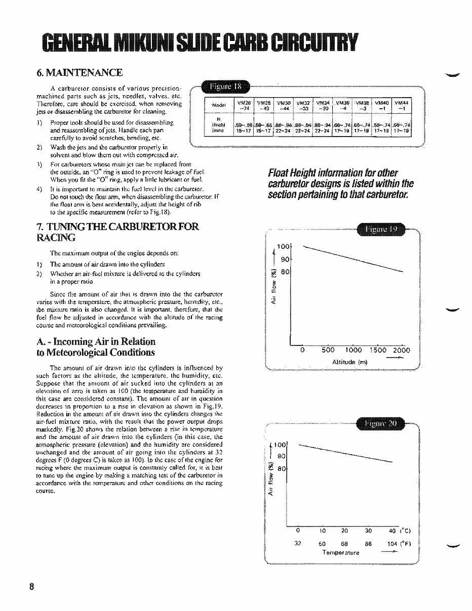
(I SUDECARB 6. MAINTENANCE A carburetor cOllsisls of various precision- machined parts such as jets, needles, valves, ele, lIell"""'<:;, care should be exercised, when removing or disassembling !l1l: carburetor for I) Proper tools should be used for 1'1\.<1.<, ... ,,1,,1 OM'''' and reassembling Handle each part carefully 10 avoid scralches, elc. 2) Wash the jets and the carburetor solvent and blow them out with ... "'m .... ,..,.·<r>rI alf. 3) For carburetors whose mainjel can be replaced from the oUlSide.. an "0" is used 10 leakage of fuel. Wllen you fil the "0" apply a lubricant or fuel. 4) II is importanllo maintain the fuel level in the carhurelor. J:)() nOI touch the noat ann, when the carburetor. [f the Aoat arm is benl accidentally, of rib 10 the specific measurement (refer to TUNlNGlHE CARBURElORFOR RACING 'n)e maximum output o(the engioe depends on: 1) The amount of air drawn into Ihe cylinders 2) Wlu:ther an air-fuel mix\l..!re is delivered to the in iii proper ratio Since the amount of air that is drawn inlo the the carburetor varies with the temperature, the pressure, humidity, eIC., Lbe IJ"I.ixmre ralio is also II is therefore, thaI the fuel flow be adjusted in accordance the altitude of the racing course and meteorological condilions A. - in Relation to Meteorological Conditions The amount of air drawn inlo the cylinders is innuenced by such factors as the altitude, Ihe temperature, the clc. that the amount of air sucked into the elevation of zero is taken as 100 (the teillperarure humidity in this case are considered The amount or air in question decreases in proportion to a rise elevation as shown in Fig.19. Reduction in tllC amount of air drawn into the cylinders changes the air-fuel mixture ralio, with the result that the power output drops m!lfkedly. Fig.20 shows the relation between II rise in lemperature and the amount of air drawn into Ihe cylinders (in this case, the and the humidi!y are considered the amount of air going into the cylinders al 32 C) is taken as 100). lo the case of the for where maximum output is constantly called best 10 tUIlc up the engine by making a lesE of the carburetor in aceordance with the lemperature and otheT conditions on [he course. Float Height information for other carburetor designs listed within the section pertaining to that carburetor. 100 t 90 ~ 80 ~ o :;: b <t. t lOD 90 ~ 80 ~ :;: '- <t. a o 31 500 1000 1500 2000 Altitude 1m) 10 50 20 68 Temperature 30 8S - 40 104 (oFl -
This Complete Service Repair Workshop Manual is an invaluable resource for anyone looking to perform maintenance or repairs on Mikuni Throttle Valves Carburetors.
DESCRIPTION:
This manual provides comprehensive coverage of all Service & Repair Procedures, offering easy-to-follow step-by-step instructions and detailed pictures for all servicing and repairs. Whether you are a professional mechanic or a DIY enthusiast, this manual will enable you to save money by tackling repairs on your own.
MODELS COVERED:
All Models/Engines/Trim/Transmissions Types Are Covered.
CONTENTS:
This high-quality Service Repair Workshop Manual encompasses all repair procedures from A to Z, ensuring that every repair and service procedure is thoroughly explained.
COMPUTER REQUIREMENTS:
This downloadable Manual is compatible with all PC & MAC Computers, tablets, and mobile phones. The only software required is Adobe Reader, which is typically pre-installed on most computers. If not, it can be easily downloaded for free.
INSTANT DELIVERY:
Upon payment confirmation via Visa, MasterCard, or PayPal, the manual will be instantly emailed to the address provided during checkout, ensuring prompt access to the valuable resource.
Customer Satisfaction Guaranteed.
Recently Viewed
5,521,897Happy Clients
2,594,462eManuals
1,120,453Trusted Sellers
15Years in Business
Price:
Actual Price:
Mikuni Throttle Valves Carburetor Complete Workshop Service Repair Manual