EN • 1 ENGLISH FRANCAIS NEDERLANDS ESPAÑOL ITALIANO DEUTSCH 664Y3000.A Installation, Operating and Servicing Instructions Prestige 50 - 75
EN • 2 ENGLISH FRANCAIS NEDERLANDS ESPAÑOL ITALIANO DEUTSCH 664Y3000.A WARNING 3 Who should read these instructions 3 Symbols 3 Recommendations 3 Applicable standards 3 Warnings 3 INTRODUCTION 4 Description of the specifications 4 USERS GUIDE 5 Directions for use 5 Settings the parameters 5 TECHNICAL CHARACTERISTICS 6 Natural gas categories 7 Propane gas categories 7 Pressure drop diagram of the boiler 7 ELECTRICAL CONNECTION 8 Wiring diagram 8 INSTALLATION INSTRUCTIONS 9 Dimensions 9 Boiler room 9 Wall mounting of the boiler 9 INSTALLATION 10 Connection to the chimney 10 Connection to the gas 11 Heating connections 11 Installation of simple heating circuit controlled by room thermostat ACV 15 12 Installation of simple heating circuit controlled by Room Unit 13 Installation of two heating circuits controlled by room thermostat ACV 15 and AM3-11 module 14 Installation of two heating circuits controlled by Room Unit and ZMC-1 module 16 Installation of three heating circuits controlled by Control Unit 18 Domestic hot water connection 19 COMMISSIONING AND MAINTENANCE 20 Commissioning the system 20 Inspection and maintenance 20 Disassembling the burner 21 Disassembling and checking the electrode 21 Disassembling the heat exchanger 21 Cleaning the heat exchanger 21 Temperature sensor resistance tables 21 MCBA PARAMETERS FOR THE SPECIALIST 22 Standby Mode 22 Settings the MCBA parameters 23 Request for information on the installation 24 Entering the code 24 MCBA parameters with code restricted access 25 Communication Mode 28 Error Mode 28 Safety stop + resolution of the fault 29 SPARE PARTS See at the end of this manual INDEX
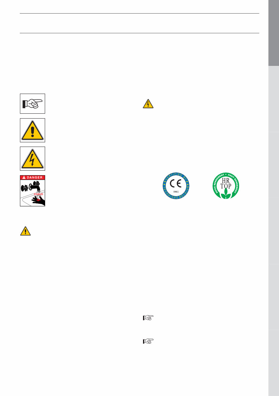
EN • 3 ENGLISH FRANCAIS NEDERLANDS ESPAÑOL ITALIANO DEUTSCH 664Y3000.A WHO SHOULD READ THESE INSTRUCTIONS These instructions should be read by: - the specifying engineer - the installer - the user - the service engineer SYMBOLS The following symbols are used in this manual: • The parts may only be replaced by genuine factory parts. You will find a list of the spare parts and their reference number ACV to the end of this document. • The burners are preset in our factory for use with natural gas [equivalent to G20]. • Specific regulation applicable in Belgium: The CO2 level, the air and gas flows and the gas / air ratio are factory set . Any field adjustments of those settings is not allowed in Belgium. • It is important to switch the boiler off before carrying out any work. • There are no user accessible parts inside the boiler casing. APPLICABLE STANDARDS The appliances carry the CE mark in accordance with the standards in force in the various countries (European Directives 92/42/EC “Efficiency”, 90/396/EC “Gas appliances”). They also carry the “HR-TOP” label (Gas condensation boilers). WARNINGS IF YOU SMELL GAS: - Immediately shut off the gas intake. - Open windows for fresh air flowing. - Do not use any electrical appliances and do not actuate any switches. - Immediately notify your gas supplier and/or your installer. This documentation is part of the information delivered with the appliance and must be given to the user and stored in a safe place! An approved installer must carry out the assembly, commissioning, maintenance and repair of the system, in accordance with current standards in force. ACV shall not accept any responsibility for damage caused by noncompliant location of the system or by use of the parts or connections not approved by ACV for this application. The manufacturer reserves the right to change the technical characteristics and specification of its products without notice. The availability of some versions and their accessories is market dependant. WARNINGS RECOMMENDATIONS • Please, read carefully this manual before installing and commissioning the boiler. • It is prohibited to carry out any modifications to the inside of the appliance without the manufacturer’s prior and written agreement. • The product must be installed and serviced by trained engineers, in compliance with current standards. • Any failure to follow instructions relating to tests and test procedures may result in personal injury or risks of pollution. • To guarantee safe and correct operation of the appliance, it is important to have it serviced and maintained every year by an approved installer or maintenance company. • In case of anomaly, please call your service engineer. • Despite the strict quality standards imposed by ACV during the manufacture, inspection and transport of its appliances, you might notice some errors. Please report immediately any fault to your approved installer. Remember to note the fault code displayed on the screen. Danger of burns Essential instruction for the safety of persons and the environment. Danger of electrocution. Essential instruction for the correct operation of the installation.
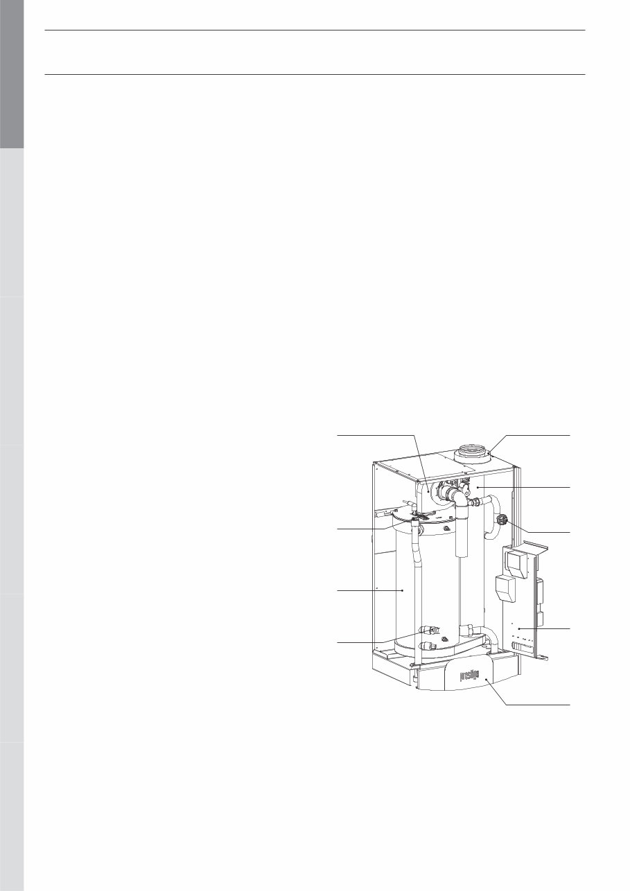
EN • 4 ENGLISH FRANCAIS NEDERLANDS ESPAÑOL ITALIANO DEUTSCH 664Y3000.A DESCRIPTION OF THE SPECIFICATIONS The Prestige is a wall-mounted condensing boiler meeting the requirements of the “HR-Top” applicable standards applicable in Belgium. The boiler is certified compliant with EC standards as a connected appliance: C13(x) - C33(x) - C43(x) - C53 - C83(x), but it can also be connected as an open appliance in category B23. LINING The boiler is protected by a steel lining that first of all undergoes a degreasing and phosphation process before being lacquered and heated at 220°C. The inside of this lining is coated with a layer of thermal and acoustic insulation, reducing losses to a minimum. HEAT EXCHANGER The core of the Prestige features a new stainless steel heat exchanger. This piece of technology represents the fruit of exhaustive research and intensive laboratory testing. It reflects ACV’s eighty years of experience in using stainless steel for heating and hot water functions. The particular geometry of the exchanger pipes is calculated to obtain a very large Reynolds number throughout its cycles. The Prestige achieves an exceptional output that remains stable throughout the boiler’s life, given that it causes no oxidation on the exchanger, which is manufactured entirely from quality stainless steel. BURNER ACV uses its BG 2000-M burner for the Prestige: this is an air/gas premix burner providing safe and silent operation while limiting emissions (NOx and CO) to an incredibly low level. Although the ACV BG 2000-M boiler is very modern, it uses proven technology and is manufactured from standard spare parts that are easily available on the market.. TEMPERATURE REGULATION The basic version of the Prestige is fitted with a microprocessor controlled regulator (MCBA) which takes over both the safety functions (ignition, monitoring the flame, limiting the temperature, etc.) and control of the boiler temperature. This MCBA also includes a weather-dependent regulator. All you need to do is connect the outdoor temperature sensor available as an option to the device. However, this regulator can also operate with a standard on/off room thermostat In addition, with the combination of a weather-dependent regulator and a room thermostat, you can control the temperatures based on the weather with compensation for the indoor temperature. There are four user adjustable parameters. By entering a special maintenance code, qualified installers can access several other parameters to adapt the boiler to special requirements. In principle, these parameters are factory set for all normal applications. PRODUCTION OF HOT WATER • Prestige 50 / 75 Solo : is custom-designed to operate for heating only or in combination with the whole range of ACV water tanks. The SmartLine range is the number one choice for domestic applications. FROST PROTECTION The boiler is equipped with an integrated frost protection: as soon as the NTC1 flow temperature drops below 7°C, the system activates the central heating pump. As soon as the NTC1 flow temperature drops below 3°C, the system automatically ignites the burner until the temperature rises above 10°C. The pump continues to run for about 10 minutes. If an outdoor temperature sensor is connected to the system, the pump is activated as soon as the outside temperature drops below the specified threshold. To provide efficient protection for the whole system against frost, all the valves on the radiators and the convectors should be completely open. Description of the boiler 1. Burner, premix and modulating 2. Manual air vent 3. Heat exchanger, stainless steel 4. Water pressure safety switch 5. Chimney connection concentric tubes Ø 100/150 mm 6. Flue tube 7. Gaz pressure safety switch 8. Electrical panel 9. Control panel INTRODUCTION 5 1 2 4 8 9 7 3 6
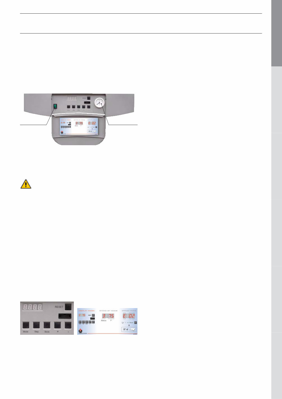
EN • 5 ENGLISH FRANCAIS NEDERLANDS ESPAÑOL ITALIANO DEUTSCH 664Y3000.A DIRECTIONS FOR USE Your system must be checked once a year by an approved installer or maintenance company. Starting the burner During operation, the burner starts automatically as soon as the boiler temperature drops under the required set point and it stops as soon as the boiler reaches that temperature. Control panel Heating system The central heating circuit must be pressurized (see in the chapter “Installation” how to define the system pressure). The pressure indicator is located on the right-hand side of the display. If your system needs to be refilled more than twice a year, please contact your installer. The CH pressure must be a minimum of 1 bar and must be checked by the end user on a regular basis. If the pressure drops under 0.5 bar, the integrated water pressure switch blocks the appliance until the pressure in the system returns to a level above 0.8 bar. The connection for a fill valve is provided underneath the appliance. The installer can also fit the system with a separate valve. Make sure that the appliance is powered off when filling the system. TTo do this, toggle the Start/Stop switch located on the left of the screen to Off. (see the Control panel). For more information, please ask your installer when the system is delivered. A safety valve is provided at the underneath of the appliance. If the system pressure exceeds 3 bars, this valve opens and drains the water from the system. In this case, please contact your installer. SETTING THE PARAMETERS Setting the domestic hot water temperature (Hot water temperature) - Press Mode: The screen displays PARA. - Press Step: the first character is 1 and the last two characters give the current hot water temperature setting. - To change this temperature, press + or - until the last two digits show the desired temperature value. - Press Store to save the new temperature setting. - Press Mode twice to return to Pilot mode (normal operating mode). Enabling or disabling the hot water heating mode (hot water) - Press Mode: The screen displays PARA. - Press Step twice: the first character is 2 and the last two characters give the current setting: 00 = disabled; 01 = enabled. - To change this parameter, press + or - until the screen displays the desired value: 00 = disabled; 01 = enabled. - Press Store to save. - Press Mode twice to return to Pilot mode (normal operating mode). Enabling or disabling Central Heating mode: (heating) - Press Mode: The screen displays PARA. - Press Step three times: the first character is 3 and the last two characters give the current setting: 00 = disabled; 01 = enabled. - To change this parameter, press + or - until the screen displays the desired value: 00 = disabled; 01 = enabled. - Press Store to save. - Press Mode twice to return to Pilot mode (normal operating mode). Setting the central heating temperature: (maximum temperature for the heating circuit) - Press Mode: The screen displays PARA. - Press Step four times: the first character is 4 and the last two characters give the current central heating temperature setting. - To change this temperature, press + or - until the last two digits show the desired temperature value. - Press Store to save the new temperature setting. - Press Mode twice to return to Pilot mode (normal operating mode). Fault: The temperature setting for the appliance and the safety functions for its various parts are continuously monitored by a regulator controlled by a microprocessor (the MCBA). In the event of a fault, this MCBA disables the appliance and displays an error code: the screen flashes displaying E as the first character, followed by the error code. To reset the appliance: - Press "Reset" on the screen. - Contact your installer of the fault happens again. Start/Stop switch Pressure gauge Also see the user label located inside the valve on the control panel: USERS GUIDE
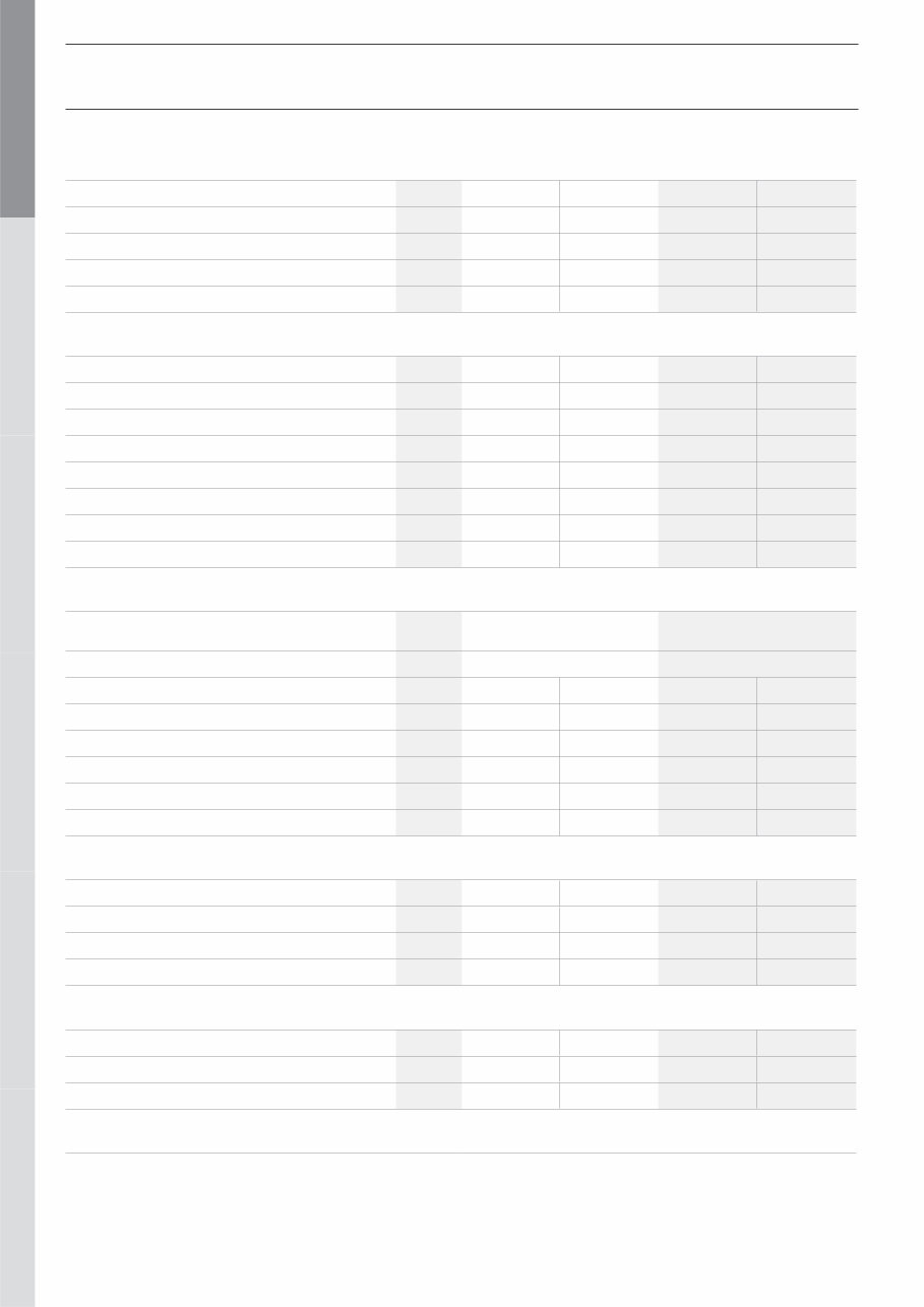
EN • 6 ENGLISH FRANCAIS NEDERLANDS ESPAÑOL ITALIANO DEUTSCH 664Y3000.A TECHNICAL CHARACTERISTICS Natural gas Propane gas Central heating 50 75 50 75 Max [intake] pressure kW 49,9 72 49,9 72 Min. [intake] pressure kW 15 18,3 15 18,3 Max output 80/60°C kW 48,4 69,9 48,4 69,9 Min. output 80/60°C kW 14,7 17,9 14,7 17,9 Efficiency at 30% load [EN677] % 107,8 107,8 107,8 107,8 Flue gases CO emissions max. / min. Input mg/kWh 45 / 20 52 / 20 89 / ?? 118 / 37 NOx emissions [EN483] mg/kWh 66 / 30 62 / 38 70 / 53 71 / 60 NOx classification [EN483] 5 5 5 5 Flue gas temperature — max. Input 80/60°C °C 82 82 80 80 Flue gas temperature — max. Input 50/30°C °C 40 40 39 39 Mass flow rate of combustion products kg/h 79 115 79 115 Flue gas pipe - Max. pressure drop Pa 150 150 150 150 Concentric flue gas channel maximum length Ø 100 / 150 mm m 20 20 20 20 Gas G20 / G25 G31 Category [varies by country] I 2E[S]B — I 2Er — I 2H — I 2 HS I 2ELL — I 2L — I 2E I 3P — I 3+ — I 3B Gas pressure mbar 20 / 25 30 / 37 / 50 G20 gas flow rate m 3 /h 5,28 7,6 • • G25 gas flow rate m 3 /h 6,14 8,8 • • G31 gas flow rate m 3 /h • • 2,0 2,9 CO 2 max. Input G20/25 (with front panel closed) % CO 2 9,4 9,4 10,8 10,8 CO 2 max. Input G20/25 (with front panel open) % CO 2 9,2 9,2 10,5 10,5 CO 2 min. Input G20/25 (with front panel closed) % CO 2 9,3 9,3 10,4 10,4 Hydraulic parameters Max. operating temperature °C 90 90 90 90 Boiler water capacity L 20 17 20 17 Maximum operating pressure central heating bar 3 3 3 3 Heat exchanger pressure drop [ΔT = 20°C] mbar 30 74 30 74 Electrical connection Class IP 30 30 30 30 Supply voltage V/Hz 230 / 50 230 / 50 230 / 50 230 / 50 Maximum absorbed electrical power A 0,8 1,1 0,8 1,1 Weight (empty) kg 54 58 54 58
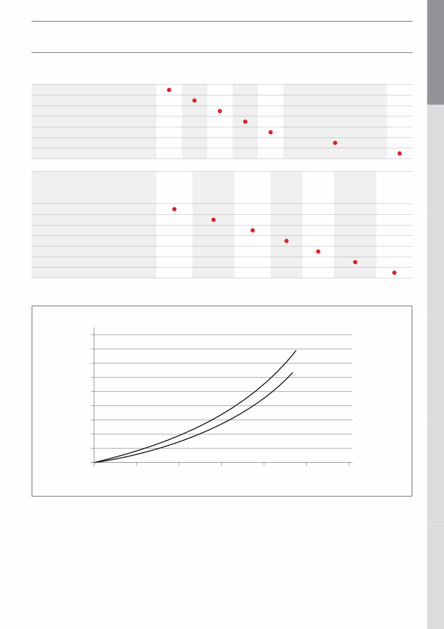
EN • 7 ENGLISH FRANCAIS NEDERLANDS ESPAÑOL ITALIANO DEUTSCH 664Y3000.A TECHNICAL CHARACTERISTICS Natural gas categories BE FR NL LU DE AT - CH - CZ - DK - ES - IT FI - UK - IE - PT - SE - GR HU I 2 E(S)B G20 / 20 mbar – G25 / 25 mbar I 2 Er G20 / 20 mbar – G25 / 25 mbar I 2 L G25 / 25 mbar I 2 E G20 / 20 mbar I 2 ELL G20 / 20 mbar – G25 / 20 mbar I 2 H G20 / 20 mbar I 2 HS G20 / 25 mbar PRESSURE DROP DIAGRAM OF THE BOILER 0 20 40 60 80 100 120 140 160 180 1 2 3 4 5 6 Prestige 75 Prestige 50 m 3 /h mbars Propane categories DK - NL NO - IT BE - CH - ES FR - UK - IE PT - FI - SE IT - GR AT - CH CZ - ES NL - DE LU - HU BE - CH ES - FR UK - IE IT - PT PT CZ - DK - ES FI - FR - UK IE - IT - NL NO - PT - SE AT - CH CZ - DE FR I 3P [G31] 30 mbar I 3P [G31] 37 mbar I 3P [G31] 50 mbar I 3+ [G30 + G31] 28 - 30 / 37 mbar I 3+ [G30 + G31] 50 / 67 mbar I 3B [G30] 28 / 30 mbar I 3B [G30] 50 mbar
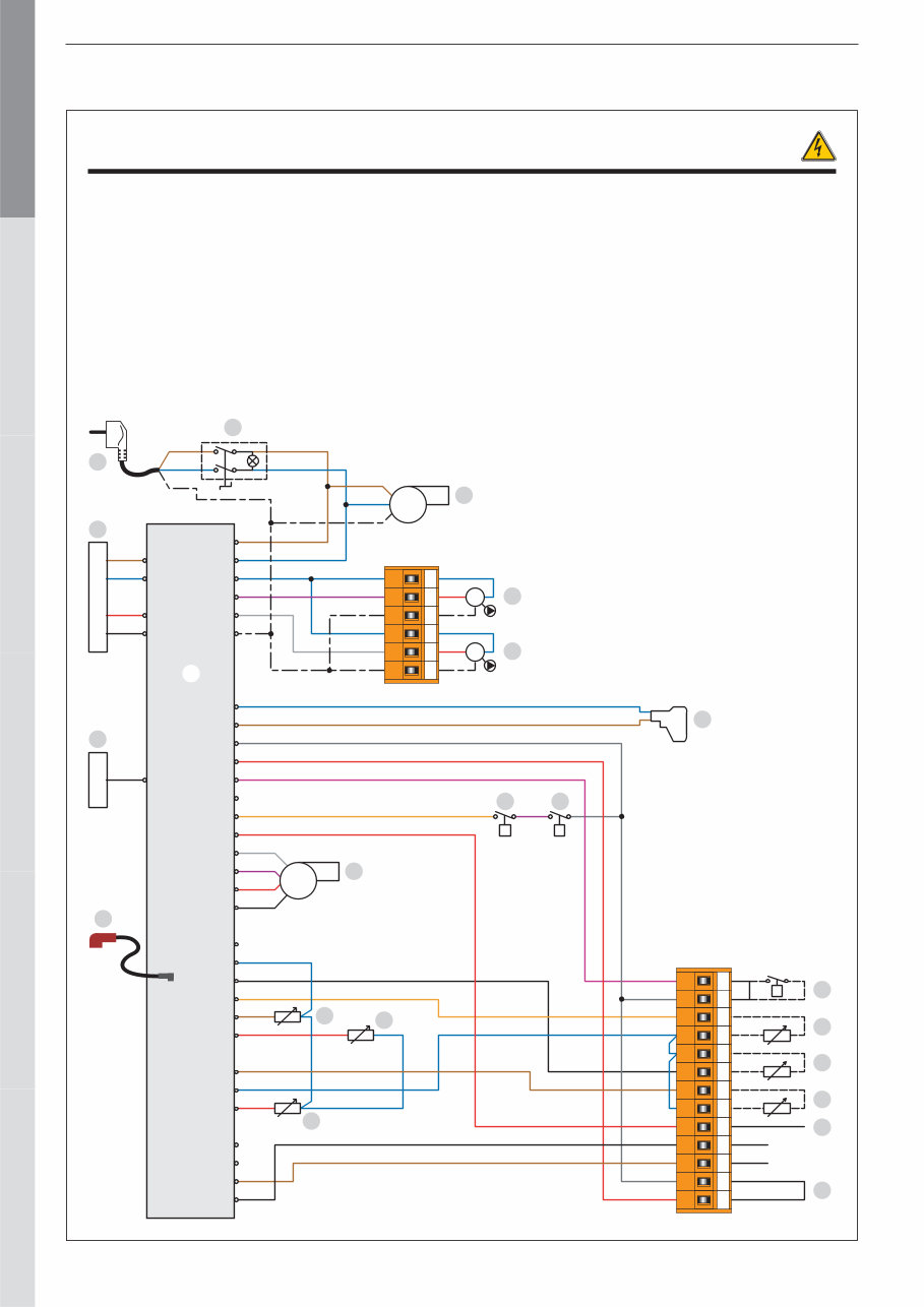
EN • 8 ENGLISH FRANCAIS NEDERLANDS ESPAÑOL ITALIANO DEUTSCH 664Y3000.A 230V Br B Br B Y/Gr M M P P t BUS B BUS A X11. X12. Br B Y/Gr Br B B Br B R Bk V W Y/Gr B Br B Br G R V G R V Or Or V G R W V R Bk B Bk Or Br R R B Br B R B Br Bk V G Or B Bk Br R Bk Br G R B V Y/Gr Y/Gr B W B R Y/Gr Y/Gr B R B B B X1.6 X1.5 X1.4 X1.3 X1.2 X7 X10.6 X10.7 X10.1 X10.3 X1.1 X2.12 X2.11 X2.10 X2.9 X2.8 X2.7 X2.6 X2.5 X2.4 X2.3 X2.2 X2.1 X3.6 X3.5 X3.4 X3.3 X3.2 X3.1 X4.3 X4.2 X4.1 X5.4 X5.3 X5.2 X5.1 1 2 3 4 5 6 7 8 9 10 11 12 13 1 2 3 4 5 6 ELECTRICAL CONNECTION WIRING DIAGRAM : PRESTIGE 50 - 75 1. 230V connection cord 2. ON/OFF switch 3. Heating pump (optional) 4. Domestic hot water pump (optional) 5. Burner 6. Gas valve 7. 230 - 24Volt transformer 8. MCBA burner control 9. Display 10. Gas pressure safety switch 11. Water pressure safety switch B. Blue Bk. Black Br. Brown G. Grey Or. Orange R. Red V. Violet W. White Y/Gr. Yellow/Green 12. PWM connector on the blower 13. NTC1 flow sensor 14. NTC2 return sensor 15. NTC5 flue gas temperature sensor 16. Room thermostat (optional) 17. NTC3 domestic hot water sensor (optional) 18. NTC4 outdoor temperature sensor (optional) 19. NTC6 temperature sensor on second CH circuit (optional) 20. Zero volt of 24V circuit. 21. Safety thermostat RAM (optional) 22. Ionisation and ignition cable 1 2 3 4 5 6 7 9 8 10 11 12 13 14 15 16 17 18 19 20 21 22
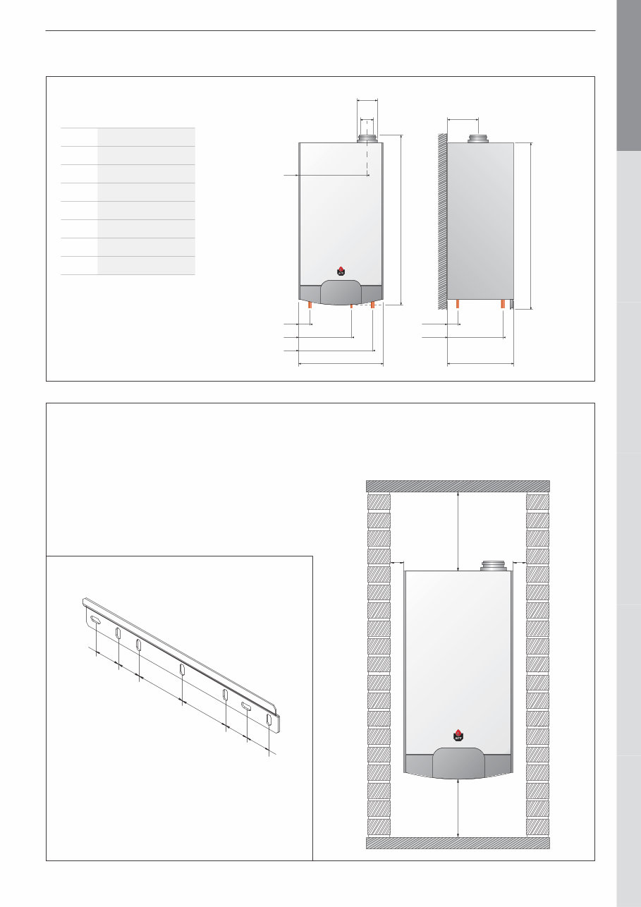
EN • 9 ENGLISH FRANCAIS NEDERLANDS ESPAÑOL ITALIANO DEUTSCH 664Y3000.A INSTALLATION INSTRUCTIONS Min. 300 mm Min. 220 mm Min. 25 mm Min. 25 mm prestige - The boiler must be mounted on a non-flammable wall. - Drill two 10 mm diameter holes, spaced as indicated on the above drawing. - Secure the wall-mount bracket with the delivered anchor screws. - Hook the boiler on the bracket. BOILER ROOM - Make sure that all air vents are unobstructed any times. - Do not store any flammable products in the boiler room. - Do not store any corrosive products, paint, solvents, salts, chlorine products and other detergent products near the appliance. - If you smell gas, do not switch on any lights, turn off the gas tap at the meter, ventilate the rooms and contact your installer. 101,6 mm 101,6 mm 48,4 mm 53,2 mm 53,2 mm 48,4 mm WALL MOUNTING OF THE BOILER 288 48 I / J K I K 65 316 J 435 prestige C D E F B H G A DIMENSIONS 50 / 75 A mm 980 B mm 500 C mm 392 D mm 100 E mm 150 F mm 175 G mm 930 H mm 400 ACCESSIBILITY The appliance must be positioned in such a way to be accessible any time. In addition, the following distances are required around the appliance. I. Heating supply 1”1/4 [F] J. Heating return 1”1/4 [F] K. Gas connection 3/4” [M]
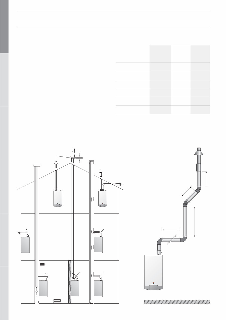
EN • 10 ENGLISH FRANCAIS NEDERLANDS ESPAÑOL ITALIANO DEUTSCH 664Y3000.A INSTALLATION CONNECTION TO THE CHIMNEY - The chimney connections must comply with the applicable standards (in Belgium: NBN D51-003), the local energy supplier’s instructions, the fire regulation and neighbourhood good practices. - The Prestige has an in built gas/air ratio regulator, which makes it largely independent of the pressure drop in the air intake and flue gas extraction system. However, the maximum pressure drop for this system may not be exceeded, or the pressure will diminish. Nevertheless, the gas/air ratio regulator continuously guarantees optimum combustion with very low emission levels. - The horizontal flue gas pipes must always be installed with a min. slope of 5 mm per meter, upwards from the boiler side. - There must be no obstruction or openings for any other appliances within a radius of 0.5 metres around the flue terminal of the Prestige. - The maximum flue resistance is 150 Pascal. You can use the following table as the basis for calculating this value (please also refer to the specimen calculation presented under the table). prestige 1000 mm 1000 mm 2000 mm 2000 mm prestige prestige C53 C33 150 min. 120 C13 B 23 C43 C43 C33 Sample calculation: The diagram below consists of the following parts: pipe with monitoring section + 2 * 90° pipe bends + 2 metres of horizontal pipe + 2 * 45° pipe bends + (2 + 1 + 1) metres of vertical pipe and fall back + discharge. Therefore, the resistance of this system is as follows: 3 + (2 x 12) + (2 x 6) + (2 x 5,5) + (4 x 6) + 25 = 99 Pa. This value is less than the maximum authorised resistance, therefore the installation is compliant. Options for connection to the chimney Table of flue resistance in Pascal (1 Pascal = 0,01 mbar) Pipe concentric Ø 100 / 150 mm Air inlet separate Ø 100 mm Air extraction separate Ø 100 mm 1 m straight pipe 6 1,7 2,5 Pipe with a monitoring section 3 — 1,3 90° pipe bend 12 5,1 7 45° pipe bend 5,5 2,1 3 Vertical pipe outlet 25 — — Horizontal pipe outlet 20 — — This table is based on the equipment offered by ACV and cannot be applied generally.
This manual is a comprehensive guide for the Prestige Boiler, covering models Prestige 50 and 75. It includes detailed Installation, Operating, and Servicing Instructions in PDF format. The contents of the manual encompass important sections such as Warning, Introduction, User Guide, Technical Characteristics, Electrical Connection, Installation Instructions, Commissioning and Maintenance, and Spare Parts.
With excellent resolution, this 38-page manual ensures that you have the flexibility to print the entire document or specific sections as per your requirements. It is designed for instant access after purchase, allowing you to store a copy for immediate use and backup purposes.
Whether you are a professional mechanic or a DIY enthusiast, this manual provides all the necessary information for the installation, operation, and servicing of your Prestige boiler system.

")