
 Forklift Service Manual")
Hyster C187 (S60XL) Forklift Service Manual
What's Included?
Fast Download Speeds
Offline Viewing
Access Contents & Bookmarks
Full Search Facility
Print one or all pages of your manual
MICROPROCESSOR
SPARK TIMING SYSTEM
(MSTS)
LATE MODEL
GM 3.0L AND 4.3L LPG FUEL ENGINES
PART NO. 1473385 2200 SRM 765

SAFETY PRECAUTIONS
MAINTENANCE AND REPAIR
• When lifting parts or assemblies, make sure all slings, chains, or cables are correctly
fastened, and that the load being lifted is balanced. Make sure the crane, cables, and
chains have the capacity to support the weight of the load.
• Do not lift heavy parts by hand, use a lifting mechanism.
• Wear safety glasses.
• DISCONNECT THE BATTERY CONNECTOR before doing any maintenance or repair
on electric lift trucks.
• Disconnect the battery ground cable on internal combustion lift trucks.
• Always use correct blocks to prevent the unit from rolling or falling. See HOW TO PUT
THE LIFT TRUCK ON BLOCKS in the Operating Manual or the Periodic Mainte-
nance section.
• Keep the unit clean and the working area clean and orderly.
• Use the correct tools for the job.
• Keep the tools clean and in good condition.
• Always use HYSTER APPROVED parts when making repairs. Replacement parts
must meet or exceed the specifications of the original equipment manufacturer.
• Make sure all nuts, bolts, snap rings, and other fastening devices are removed before
using force to remove parts.
• Always fasten a DO NOT OPERATE tag to the controls of the unit when making repairs,
or if the unit needs repairs.
• Be sure to follow the WARNING and CAUTION notes in the instructions.
• Gasoline, Liquid Petroleum Gas (LPG), Compressed Natural Gas (CNG), and Diesel fuel
are flammable. Be sure to follow the necessary safety precautions when handling these
fuels and when working on these fuel systems.
• Batteries generate flammable gas when they are being charged. Keep fire and sparks
away from the area. Make sure the area is well ventilated.
NOTE: The following symbols and words indicate safety information in this
manual:
WARNING
Indicates a condition that can cause immediate death or injury!
CAUTION
Indicates a condition that can cause property damage!

Microprocessor Spark Timing System (MSTS) Table of Contents
TABLE OF CONTENTS
General ............................................................................................................................................................... 1
Description ......................................................................................................................................................... 2
What MSTS Does ........................................................................................................................................... 2
How MSTS Begins Operation ....................................................................................................................... 2
Operation ............................................................................................................................................................ 3
Distributor ..................................................................................................................................................... 3
Ignition Coil ................................................................................................................................................... 3
Ignition Module.............................................................................................................................................. 3
When Engine Is Being Started ..................................................................................................................... 4
When Engine Is Running .............................................................................................................................. 5
Manifold Absolute Pressure (MAP) Sensor .................................................................................................. 6
Engine Coolant Temperature (ECT) Sensor................................................................................................. 6
MSTS Module Corrections ............................................................................................................................ 7
Troubleshooting .................................................................................................................................................. 8
General ........................................................................................................................................................... 8
Tools and Test Equipment ............................................................................................................................. 10
MSTS .............................................................................................................................................................. 11
Troubleshooting Procedure............................................................................................................................ 11
Where to Start ........................................................................................................................................... 11
Visual/Physical Inspection ........................................................................................................................ 11
Knowledge/Tools Required ........................................................................................................................ 11
Damage from Static Discharge (Static Electricity) ................................................................................. 11
Troubleshooting Information ........................................................................................................................ 12
Malfunction Indicator Lamp (MIL) .......................................................................................................... 12
Connecting CodeMate Tester .................................................................................................................... 12
Reading Diagnostic Trouble Codes (DTC) ................................................................................................ 13
Clearing Diagnostic Trouble Codes (DTC’s) ............................................................................................. 14
On-Board Diagnostic (OBD) System Check ................................................................................................. 14
Test Description ......................................................................................................................................... 14
No Malfunction Indicator Lamp........................................................................................................................ 16
Circuit Description ........................................................................................................................................ 16
Test Description ............................................................................................................................................. 16
No DTC-12, Malfunction Indicator Lamp ON .................................................................................................. 18
Circuit Description ........................................................................................................................................ 18
Test Description ............................................................................................................................................. 18
Starter Rotates Engine, Engine Does Not Run ................................................................................................ 19
Test Description ............................................................................................................................................. 19
DTC-14 Engine Coolant Temperature (ECT) (Low Temperature Indicated).................................................. 23
Circuit Description ........................................................................................................................................ 23
Test Description ............................................................................................................................................. 23
DTC-15 Engine Coolant Temperature Sensor (ECT) (High Temperature Indicated) .................................... 25
Circuit Description ........................................................................................................................................ 25
Test Description ............................................................................................................................................. 25
DTC-34 Manifold Absolute Pressure (MAP) Sensor ........................................................................................ 27
Circuit Description ........................................................................................................................................ 27
Test Description ............................................................................................................................................. 27
DTC-41 Electronic Spark Timing (EST) Open Circuit..................................................................................... 30
Circuit Description ........................................................................................................................................ 30
Test Description ............................................................................................................................................. 30
DTC-42 Electronic Spark Timing (EST) Grounded Circuit ............................................................................. 32
Circuit Description ........................................................................................................................................ 32
©2002 HYSTER COMPANY i

Table of Contents Microprocessor Spark Timing System (MSTS)
TABLE OF CONTENTS (Continued)
Test Description ............................................................................................................................................. 32
DTC-51 MSTS Failure ....................................................................................................................................... 34
Circuit Description ........................................................................................................................................ 34
Distributor Repair.............................................................................................................................................. 34
Remove ........................................................................................................................................................... 34
Disassemble ................................................................................................................................................... 35
Inspect ............................................................................................................................................................ 35
Assemble ........................................................................................................................................................ 35
Install ............................................................................................................................................................. 36
Ignition Timing .............................................................................................................................................. 36
Ignition Module Repair ...................................................................................................................................... 37
Test For Fault ................................................................................................................................................ 37
Replace ........................................................................................................................................................... 38
Sensing Coil Repair ........................................................................................................................................... 38
Test For Fault ................................................................................................................................................ 38
Replace ........................................................................................................................................................... 38
Ignition Coil Repair ........................................................................................................................................... 39
Test For Fault ................................................................................................................................................ 39
Remove ........................................................................................................................................................... 39
Install ............................................................................................................................................................. 39
MSTS Module Repair......................................................................................................................................... 40
Remove ........................................................................................................................................................... 40
Install ............................................................................................................................................................. 40
ECT Sensor Replacement .................................................................................................................................. 40
MAP Sensor Replacement ................................................................................................................................. 41
This section is for the following models:
GM 3.0L and 4.3L LPG Fuel Engines
ii
2200 SRM 765 General
General
This section describes the operation of the Micropro-
cessor Spark Timing System (MSTS). The MSTS ig-
nition system is used on engines that use an LPG fuel
system. The description, operation, troubleshooting,
and repair of the MSTS is identical for both the GM
3.0L and 4.3L engines. Illustrations in this man-
ual show the MSTS in the 3.0L engine only. Repairs
and Troubleshooting procedures are also in this sec-
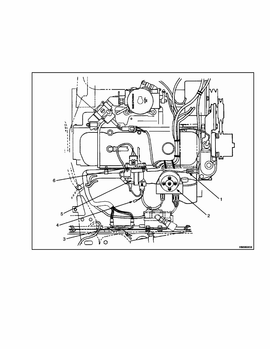
tion. Typical installation of the MSTS is shown in
Figure 1.
1. ENGINE COOLANT TEMPERATURE (ECT)
SENSOR
2. DISTRIBUTOR
3. MSTS MODULE
4. TACHOMETER CONNECTOR
5. IGNITION COIL
6. MAP SENSOR
Figure 1. MSTS Arrangement in Engine Compartment (Typical)
1
You're Reading a Preview
What's Included?
Fast Download Speeds
Offline Viewing
Access Contents & Bookmarks
Full Search Facility
Print one or all pages of your manual
$41.99
Viewed 37 Times Today


Secure transaction
What's Included?
Fast Download Speeds
Offline Viewing
Access Contents & Bookmarks
Full Search Facility
Print one or all pages of your manual
$41.99
This manual contains maintenance and repair procedures for the Hyster C187 (S60XL) Forklift.
- Hyster C187 (S60XL) Forklift Service Repair Factory Manual is an electronic version of the best original maintenance manual. It can zoom in anywhere on your computer for clear viewing. The parts correspond with the number of pages printed on it in this manual, making it very easy to use.
- Covers the following models:
- Hyster C187 (S60XL) Forklift Service Repair Factory Manual
- Service Repair Factory Manual Covers:
- Alternator with regulator
- Brake system
- Capacities and specifications
- Carburetor
- Chain drive assembly for the hydraulic pump
- Cooling system
- Drive axle
- Electrical systems for the isuzu c240 (2.4l) diesel engine
- Electrical systems of the mazda m4-121g gasoline or lpg engine
- Engine and fuel system
- Engine
- Frame and connected parts
- Gauges
- Hydraulic system and gear pump assembly
- Lift cylinders
- Lpg fuel system
- Main control valve and auxiliary solenoid valve
- Mast
- Mazda m4-121g engine
- Metric and inch (sae) fasteners
- Microprocessor spark timing system (msts)
- Periodic maintenance
- Rochester carburetor
- Schematic
- Single-speed powershift transmisson
- Starter
- Steering axle
- Steering control unit
- Steering system
- Tilt cylinders
- Vista mast
- Hyster C187 (S60XL) Forklift Service Repair Factory Manual is written step by step in detail, making it easy to repair by yourself and save expenses.
- File Format:
- Compatible: All Versions of Windows & Mac
- Language: English
- Requirements: Adobe Reader
Do not hesitate, after your payment, you will immediately get the manual.
Hyster C187 (S60XL) Forklift Service Manual


