DOOSAN lift fork truck MicroController Control Systems Manual B20S-5 B25S-5 B30S-5 B32S-5 BC20S-5 BC25S-5 BC30S-5 BC32S-5 BC25SE
What's Included?
Lifetime Access
Fast Download Speeds
Online & Offline Access
Access PDF Contents & Bookmarks
Full Search Facility
Print one or all pages of your manual
Specifications Systems Operation Testing & Adjusting MicroController Control Systems B20S-5, B25S-5, B30S-5, B32S-5 BC20S-5, BC25S-5, BC30S-5, BC32S-5 BC25SE-5 for Electric Lift Trucks SB4200E00 Oct. 2006
1 Important Safety Information Most accidents involving product operation, maintenance and repair are caused by failure to observe basic safety rules or precautions. An accident can often be avoided by recognizing potentially hazardous situations before an accident occurs. A person must be alert to potential hazards. This person should also have the necessary training, skills and tools to perform these functions properly. Improper operation, lubrication, maintenance or repair of this product can be dangerous and could result in injury or death. Do not operate or perform any lubrication, maintenance or repair on this product, until you have read and understood the operation, lubrication, maintenance and repair information. Safety precautions and warnings are provided in this manual and on the product. If these hazard warnings are not heeded, bodily injury or death could occur to you or other persons. The hazards are identified by the “Safety Alert Symbol” and followed by a “Signal Word” such as “WARNING” as shown below. The meaning of this safety alert symbol is as follows: Attention ! Become Alert ! Your Safety is Involved. The message that appears under the warning, explaining the hazard, can be either written or pictorially presented. Operations that may cause product damage are identified by NOTICE labels on the product and in this publication. DOOSAN cannot anticipate every possible circumstance that might involve a potential hazard. The warnings in this publication and on the product are therefore not all inclusive. If a tool, procedure, work method or operating technique not specifically recommended by DOOSAN is used, you must satisfy yourself that it is safe for you and others. You should also ensure that the product will not be damaged or made unsafe by the operation, lubrication, maintenance or repair procedures you choose. The information, specifications, and illustrations in this publication are on the basis of information available at the time it was written. The specifications, torques, pressures, measurements, adjustments, illustrations, and other items can change at any time. These changes can affect the service given to the product. Obtain the complete and most current information before starting any job. DOOSAN dealers have the most current information available.
3 Index Specifications Assembly Layout of Controller ............................. 10 Assembly Layout of Motors (36/48/80 V) ............ 10 B20/25/30/32S-5 Motors ........................................ 8 BC20/25/30/32S-5 Motors ..................................... 7 Component Measurements ................................... 5 Controller AS Specification .................................... 6 Control Panel Layout ........................................... 11 Fuses ................................................................... 10 Instrument Panel Layout ........................................ 9 Systems Operation General Information ............................................. 14 Glossary............................................................... 12 Installation and Wiring ......................................... 18 Testing and Adjusting B20/25/30/32S-5 .................................................. 43 BC20/25/30/32S-5 ............................................... 31 Preparation Tests and Check .............................. 27 Programmable Parameters.................................. 30 Some Functions Management ............................. 48 Diagnostic and Troubleshooting Alarm List ............................................................. 49 Electrical System Adjustment ............................ 101 General Description ............................................. 49 System Tests and Adjustments ......................... 100 Troubleshooting Problem List .............................. 58 Instrument Panel Accessing Stored Error Codes .......................... 121 Default Setting ................................................... 118 Diagnostic Mode ................................................ 119 Display Keys Utilization ..................................... 108 Instrument Panel................................................ 104 List of diagnostic ................................................ 120 Parameter Calibration ........................................ 109 Sensor Initial Setting .......................................... 118 Eye Software Interface General Information............................................124 Installation ..........................................................125 Features .............................................................126 Main Menu..........................................................128 Troubleshooting of Eye Program .......................158 Appendix Appendix A : 36[V] Parameter List .....................159 Appendix B : 48[V] Parameter List .....................162 Appendix C : 80[V] Parameter List .....................165 Appendix D : Parameter List ..............................168 Appendix E : Error Code List..............................171 Appendix F : Contraction for dot matrix display. 177 F1. Alarm Code ................................... 177 F2. Calibration Code ........................... 178 F3. Diagnostic Code ........................... 180
5 Specifications Component Measurements 36/48V 80V SPECIFICATIONS Multimeter Setting (+) Test Lead (-) Test Lead Results Resistance +BATT Each U,V,W Over 1.4 Mohms Resistance -BATT Each U,V,W Over 1.4 Mohms Resistance U Terminal V Terminal Below 0.5 ohms Resistance U Terminal W Terminal Below 0.5 ohms Resistance V Terminal W Terminal Below 0.5 ohms
6 Controller AS Specification TYPE 36/48 V 80 V BATTERY VOLTAGE 24-60 V MAXIMUM IMPULSIVE DRIVE INVERTER CURRENT 750 A 450A MAXIMUM IMPULSIVE PUMP INVERTER CURRENT 750 A 450A SWITCHING FREQUENCY 3-6-9 KHz ← EFFICIENCY 95 % ← PROTECTION LEVEL IP54 ← MECHANICAL SIZE 400x395x148 454x277x150 WEIGHT 24 Kg VIBRATION 5g 10-500Hz in X,Y,Z axis ← TEMPERATURE RANGE - 30 °C ¸ + 40 °C ← MAXIMUM MODULE TEMPERATURE 100°C ← CONTROLLER Complies with EN 1175-1 EN 12895-1 ← MAIN CONTACTOR 600A 250A MAIN FUSE 800A 425A KEY FUSE 10A 10A 36/48V 80V
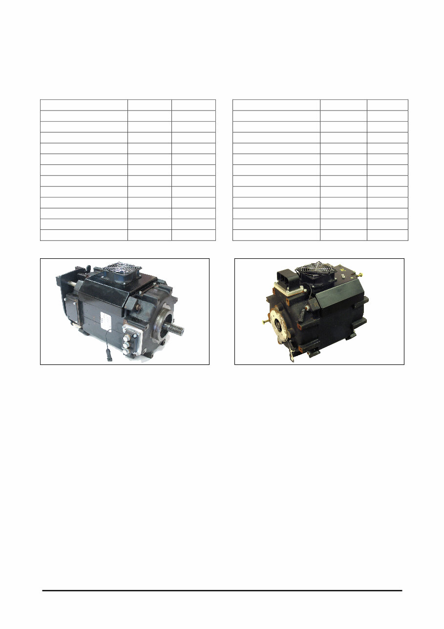
7 BC20/25/30/32S-5 Motors Drive Motor Specification TYPE 36/48 V 80 V POWER 16 KW 16 KW VOLTAGE 30 V 50 V CURRENT 441 A 259 A RATED SPEED 1500 RPM ← MAXIMUM SPEED 4500 RPM ← FREQUENCY 75 Hz ← Cos φ 0.79 0.83 SERVICE S2 60' ← INSULATION CLASS F ← PROTECTION DEGREE IP 54 ← BEARINGS 6208 2RS ← WEIGHT 122 Kg ← Pump Motor Specification TYPE 36/48 V 80 V POWER 21 KW 21 KW VOLTAGE 30 V 50 V CURRENT 580 A 348 A RATED SPEED 1540 RPM ← MAXIMUM SPEED 4500 RPM ← FREQUENCY 77 Hz ← Cos φ 0.79 ← SERVICE S3 15% ← INSULATION CLASS F ← PROTECTION DEGREE IP 54 ← BEARINGS 6208 2RS ← WEIGHT 95 Kg ←
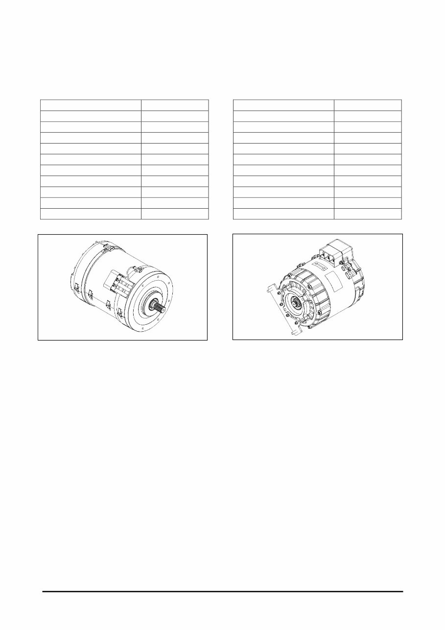
8 B20/25/30/32S-5 Motors Drive Motor Specification TYPE 48 V POWER 15.5 KW VOLTAGE 30.3 V CURRENT 405 A RATED SPEED 1735 RPM MAXIMUM SPEED 4500 RPM FREQUENCY 90 Hz Cos φ 0.83 SERVICE S2 60' INSULATION CLASS F PROTECTION DEGREE IP 20 Pump Motor Specification TYPE 48 V POWER 17 KW VOLTAGE 30.0 V CURRENT 450 A RATED SPEED 1550 RPM MAXIMUM SPEED 4500 RPM FREQUENCY 55 Hz Cos φ 0.86 SERVICE S3 15% INSULATION CLASS F PROTECTION DEGREE IP 20
These digital manuals provide comprehensive information for the maintenance and repair of Electric Lift Trucks, including the B20S-5, B25S-5, B30S-5, B32S-5, BC20S-5, BC25S-5, BC30S-5, and BC32S-5 models. The manuals cover various aspects such as Systems Operation, Testing & Adjusting, MicroController Control Systems, and more.
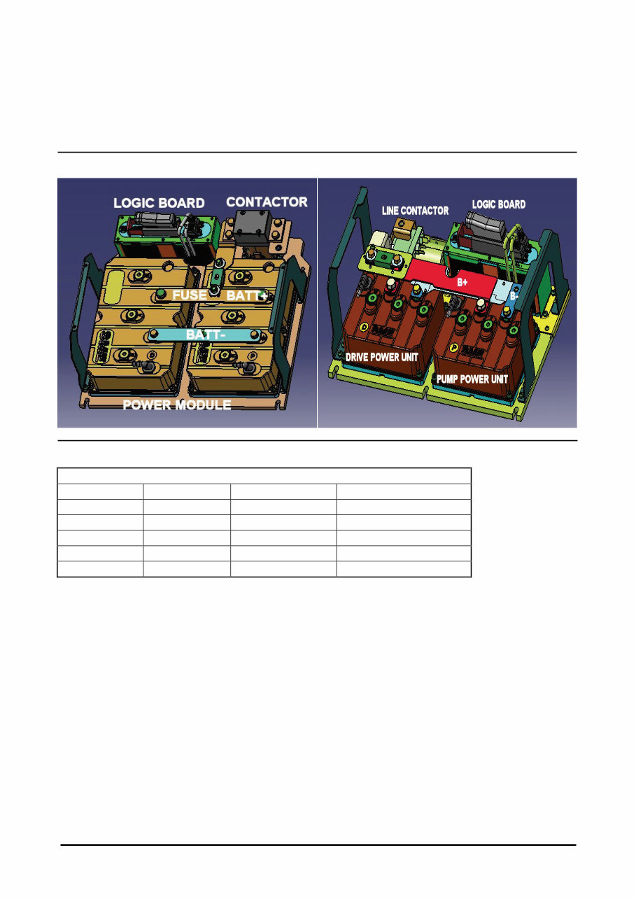
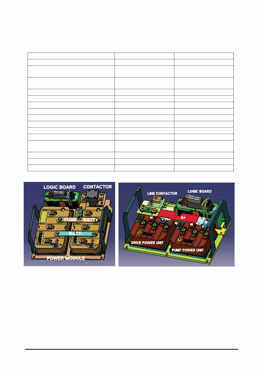
Assembly Layout of Controller - 10
Assembly Layout of Motors (36/48/80 V) - 10
B20/25/30/32S-5 Motors - 8
BC20/25/30/32S-5 Motors - 7
Component Measurements - 5
Controller AS Specification - 6
Control Panel Layout - 11
Fuses - 10
Instrument Panel Layout - 9
The manuals also include detailed information on Systems Operation, General Information, Glossary, Installation and Wiring, Testing and Adjusting, Preparation Tests and Check, Programmable Parameters, Diagnostic and Troubleshooting, Instrument Panel, Eye Software Interface, and Appendices.
General Information - 14
Glossary - 12
Installation and Wiring - 18
Testing and Adjusting for B20/25/30/32S-5 - 43
Testing and Adjusting for BC20/25/30/32S-5 - 31
Preparation Tests and Check - 27
Programmable Parameters - 30
Diagnostic and Troubleshooting including Alarm List, Electrical System Adjustment, General Description, System Tests and Adjustments, Troubleshooting Problem List, Accessing Stored Error Codes, Default Setting, Diagnostic Mode, Display Keys Utilization, Instrument Panel, List of diagnostic, Parameter Calibration, and Sensor Initial Setting.
Additionally, the manuals cover the Eye Software Interface, including General Information, Installation, Features, Main Menu, and Troubleshooting of Eye Program. The Appendices provide detailed Parameter Lists, Error Code Lists, and Contraction for dot matrix display.
Recently Viewed
5,521,897Happy Clients
2,594,462eManuals
1,120,453Trusted Sellers
15Years in Business
Price:
Actual Price:
DOOSAN lift fork truck MicroController Control Systems Manual B20S-5 B25S-5 B30S-5 B32S-5 BC20S-5 BC25S-5 BC30S-5 BC32S-5 BC25SE