Printed in Germany MA-2350-001 01 REV. 2/98 WARNING TO PREVENT SERIOUS RISK OF INJURY TO YOURSELF AND OTHERS OBSERVE THE FOLLOWING SAFETY INSTRUCTIONS GENERAL MAINTENANCE These vehicles may become hazardous if adequate maintenance is neglected. Therefore, adequate maintenance facilities, trained personnel and procedures should be provided. Maintenance and inspection shall be performed in conformance with the following practices: 1. A scheduled planned maintenance, lubrication and inspection system should be followed. 2. Only qualified and authorized personnel shall be permitted to maintain, repair, adjust and inspect vehicle. 3. Before leaving the vehicle— a. Stop vehicle. b. Fully lower the platform. c. Place directional controls in neutral. d. Turn off power (Battery disconnect). e. Remove key. f. Block the wheels if vehicle is on an incline. 4. Before working on vehicle — a. Raise drive wheels free of floor or disconnect power sources. b. Use chocks or other positive positioning devices. c. Block load engaging means, inter masts or chassis before working under them. d. Operation to check performance of vehicle or attachments shall be conducted in an author- ized safe clearance area. 5. Before starting to operate vehicle — a. Be in operating position. b. Place directional control in neutral. c. Before operating vehicle, check functions of lift systems, directional control, speed control, 6. Avoid fire hazards and have fire protection equipment present. Do not use an open flame to check level, or for leakage of electrolyte and fluids or oil. Do not use open pans of fuel or flammable cleaning fluids for cleaning parts. 7. Keep shop well ventilated, clean and dry. 8. Brakes, steering mechanisms, control mechanisms, guards and safety devices shall be inspected regularly and maintained in a safe operating condition. 9. Capacity, operation and maintenance instruction plates or decals shall be maintained in legible condition. 10. All parts of lift mechanisms shall be inspected to maintain them in safe operating condition. 11. All hydraulic systems shall be regularly inspected and maintained in conformance with good practice. Cylinders, valves and other similar parts shall be checked to assure that “drift” has not developed to the extent that it would create a hazard. 12. Batteries, motors, controllers, limit switches, protective devices, electrical conductors and connections shall be maintained in conformance with good practice. Special attention shall be paid to the condition of electrical insulation. 13. Vehicles shall be kept in a clean condition to minimize fire hazards and facilitate detection of loose or defective parts. 14. Modifications and additions which affect capacity and safe vehicle operation shall not be performed by the customer or user without manufacturers prior written approval. Capacity, operation and maintenance plates or decals shall be changed accordingly. 15. Care shall be taken to assure that all replacement parts are interchangeable with the original parts and of equal quality to that provided in the original equipment. For further information pertaining to operating and maintenance procedures refer to: • ANSI/SIA A92.6-1990 Self Propelled Elevating Work Platforms. For copies send request to: Scaffold Industry Association Inc. 14039 Sherman Way Van Nuys, CA 91405-2599
Printed in Germany Page intentionally left blank Seite absichtlich freigelassen Page intentionellement laissée blanche
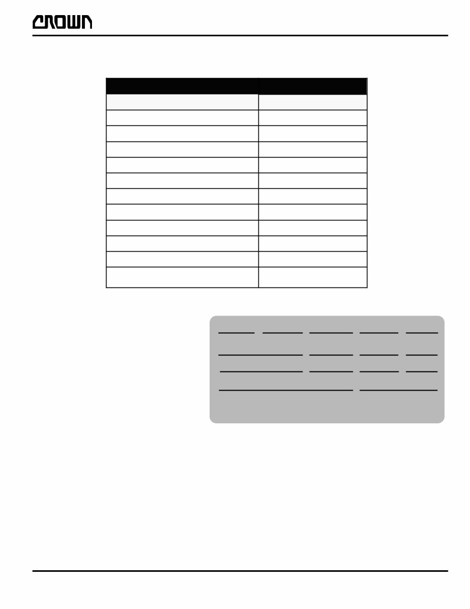
Printed in Germany IDX-2350-701 01 REV. 2/98 Battery ------------------------------------------------ M4.6–2350–500 thru –504 Service Panel --------------------------------------- M4.8–2350–001 01 - 2/98 –002 PLATFORM MAINTENANCE Platform ---------------------------------------------- M9.0–2350–500 GLOSSARY Glossary ----------------------------------------------- M10–2350–500 –501 WIRING DIAGRAMS Wiring Diagram Index ------------------------------- DIA–2350–500 01 - 2/98 thru –504 CHASSIS PARTS Front --------------------------------------------------- 01.0–2350–500 01 - 2/98 –501 Rear ---------------------------------------------------- 01.0–2350–550 01 - 2/98 Front Axle --------------------------------------------- 01.5–2350–550 HYDRAULIC PARTS Hydraulic System ----------------------------------- 02.0–2350–500 DRIVE UNIT PARTS Drive Wheel ------------------------------------------ 03.2–2350–001 ELECTRICAL PARTS Contactor Panel 24V ------------------------------- 04.1–2350–500 01 - 2/98 Contactor Emergency Disconnect -------------- 04.4–2350–500 Traction Pod ------------------------------------------ 04.6–2350–500 Steering Pod ----------------------------------------- 04.6–2350–550 Service Panel ---------------------------------------- 04.8–2350–500 01 - 2/98 –501 Gate Switch ------------------------------------------ 04.8–2350–550 01 - 2/98 Height Switch ---------------------------------------- 04.8–2350–650 01 - 2/98 Motor Cover ------------------------------------------ 04.8–2350–750 01 - 2/98 –751 Revision Title No. - Date TABLE OF CONTENTS
Printed in Germany IDX-2350-702 02 REV. 10/99 Revision Title No. - Date TABLE OF CONTENTS MAST PARTS Chain --------------------------------------------------- 07.2–2350–550 01 - 2/98 PLATFORM PARTS Platform ------------------------------------------------ 09.0–2350–500 02 - 10/99 Floorboard ---------------------------------------------- 09.0–2350–550 ACCESSORIES Aisle Guide ------------------------------------------- 10.0–2350–500
Printed in Germany ITD-2350-500 01 REV. 2/98 This manual is intended for the customer or operator who is seeking information about maintenance and service replacement parts. OPERATOR INSTRUCTIONS This manual does not contain operator instructions. Operator instructions in booklet form are sent with each vehicle. Additional copies can be ordered if required. These booklets are for you and your personnel to ensure years of safe, trouble free operation. When ordering additional copies refer to Crown publication PF12538. DRIVER TRAINING A Drivers Training Manual and Video are both shipped with each vehicle. Additional copies of each are available through your Crown Dealer. REPLACEMENT PARTS When ordering replacement parts from your Crown Dealer always specify, along with the part number, the model and serial number of the vehicle. This information will further enable your Crown Dealer to give correct, fast and efficient service. For capacities, technical information and dimensional specifications, please refer to the following sales literature: Literature CPG–12543 Specifications CPG–12545 Copies of publications or videos can be obtained from your Crown Dealer, or from: CROWN Gabelstapler GmbH Kronstadter Straße 11 81677 München Phone: +49 (0 89) 9 30 02 - 0 Fax: +49 (0 89) 9 30 02 - 133 INTRODUCTION
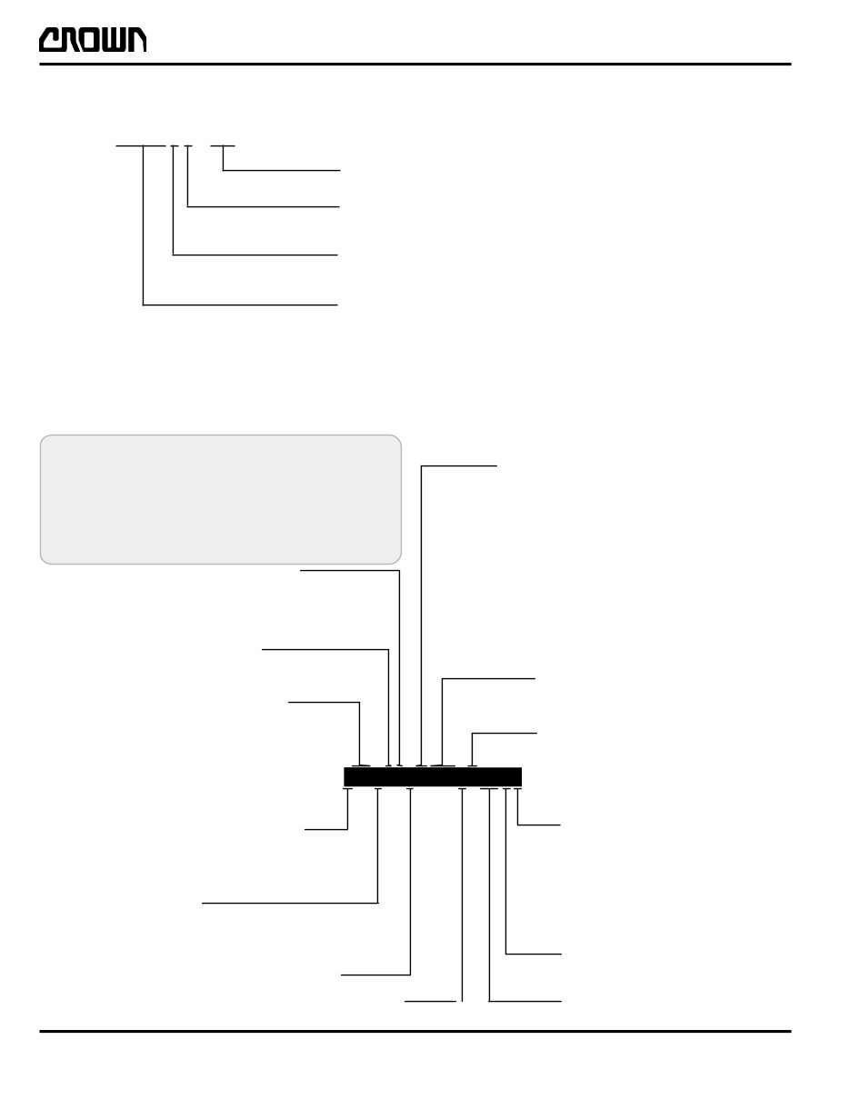
Printed in Germany 01 REV. 2/98 ITD-2350-501 This manual is arranged by major sections. The first part of the Control Number, found at the bottom of each page, denotes the section in which a particular form will be located. The first portion of the manual covers the written maintenance sections, the later portion covers replacement parts. The section descriptions are as follows: The data plate is located on the lower rear section of the third stage mast in the operator compartment and includes a model number and a truck data number. From these two numbers the vehicle model, series, series updates, vehicle size and specific truck data can be determined. The following will explain the model and vehicle data numbering system. 6174E This vehicle as released conforms to CE regulations. The user is responsible for proper operation and maintanance of this vehicle per the mandantory requirements of the country where it is operated. Load Tray Load Deck One Person Plus Tools mm Maximum Weight Capacity (Equally Distributed Load) Minimum Total Battery Weight Max. AMP Hr. Cap. Approx. Weight as Equipped. with Battery kg kg kg kg Hydraulic Pressure Voltage VDC Hour Rate Max. Grade Platform Lift Ht. Vehicle Data Number Serial Number Model Number % kg Crown Lift Trucks Ltd. Fishponds Road,Wokingham, Berkshire RG41 2JT United Kingdom 175 CL A-E Model Year bar 5 h e c n a n e t n i a M s t r a P t n e m e c a l p e R n o i t c e S n o i t p i r c s e D n o i t c e S n o i t p i r c s e D 1 M t n e m t s u j d A d n a n o i t a c i r b u L 1 s i s s a h C 2 M c i l u a r d y H 2 c i l u a r d y H 3 M t i n U e v i r D 3 t i n U e v i r D 4 M l a c i r t c e l E 4 l a c i r t c e l E 5 M d e s U t o N 5 d e s U t o N 6 M d e s U t o N 6 d e s U t o N 7 M d e s U t o N 7 t s a M 8 M d e s U t o N 8 d e s U t o N 9 M m r o f t a l P 9 m r o f t a l P 0 1 M y r a s s o l G 0 1 s e i r o s s e c c A A I D s m a r g a i D g n i r i W 1 0 0 T INTRODUCTION
Printed in Germany ITD-2350-502 6202 MODEL NUMBER EXAMPLE WAV50–84 Lift Height – 70 or 84 in. 1780 or 2135 mm Version – Characteristic that distinguishes vehicle from other versions Series Update – Significant change(s) to the product that would not merit a new series number (generation) Image Generator – Work Assist Vehicle The vehicle data number provides you and your dealer with a wealth of information to ensure the selection of proper parts for your vehicle. You may simply provide this number to your dealer, or use the following breakdown if selecting your own part numbers or service information from this manual. VEHICLE DATA NUMBER EXAMPLE K = Lift Lower L = Forward Reverse Lift M = Forward Reverse Lower N = Reverse Lift Lower O = Forward Lift Lower P = Forward Reverse Lift, Lower Q = None KE = No Hour Meter HM = Hour Meter – = No Storage 1 = One Pocket 2 = Two Pockets 1 = Wet 160 Amp. 2 = Wet 205 Amp. 3 = Maintenance Free 195 Amp. Batteries Batterie Charger Alarms A = Forward B = Reverse C = Lift D = Lower E = Forward Reverse F = Forward Lift H = Forward Lower I = Reverse Lift J = Reverse Lower Meter Storage Aisle Guide – = No Handset 1 = Handset System Controller Strobe – = No Strobe 1= Strobe Wheel Color 1 = Yellow 2 = Black Vehicle – = Standard C = Custom S = Special Lift Height 70= 70 in. (1.780 mm) 84= 84 in. (2.135 mm) 1 = 15 Amp. 2 = 25 Amp. Color 1 = Maui Yellow 2 = Seafoam Green 3 = Alpine White The example of the vehicle data number shown below is a standard vehicle with a 70 in. (1780 mm) lift height, 160 Amp. wet cell batteries, with a 15 Amp. battery charger, vehicle color of Seafoam Green, yellow wheels, with a forward travel alarm, equipped with; an hour meter, strobe light, one (1) storage pocket, aisle guidance and system controller with a handset. INTRODUCTION 35= Actual Width Language Code A = French B = German C = British English D = Spanish E = Italian F = Dutch 02 REV.10/98
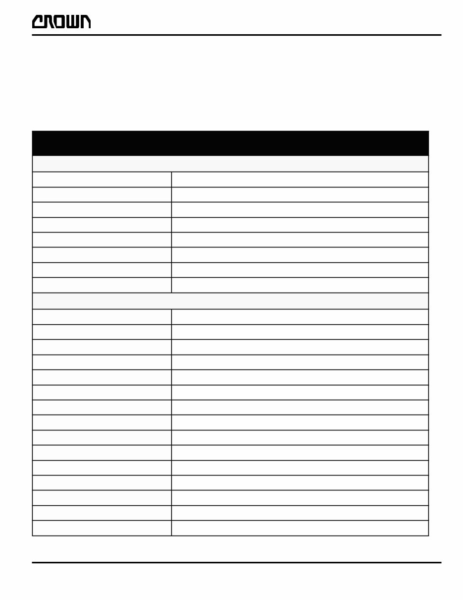
Printed in Germany M1.0-2350-001 Lubrication and Adjustment To obtain maximum life of any commercial equipment, a well planned maintenance program (PM), performed by qualified technical personnel should be followed. In conjunction with, and an integral part of, any planned maintenance program should be daily operator input. Ope- rator involvement can greatly reduce vehicle down time, assist in determining planned maintenance (PM) schedules and ultimately save money. For these reasons, Crown Before performing maintenance to any unit, it should be taken to an area set aside for maintenance or a section where there is adequate space to perform required work. This is a must to insure the safety of others and to insure that proper maintenance is performed to the unit. The operator´s daily checklist is a seperately attached part of the operator manual, delivered with the vehicle. T S I L K C E H C Y L I A D S ´ R O T A R E P O S K C E H C L A U S I V : E G A M A D s t r a p g n i s s i m r o n e k o r b , d e t n e d , t n e b o N : S K A E L e l c i h e v r e d n u r o e d i s n i e n o N : S L E E H W & S E R I T n o i t i d n o c d o o G : Y A R T D A O L h c t a l n o i t i s o p e g a r o t s , h c t a l n o i t i s o p l a c i t r e V : S N I A H C t s u r o n , e c a l p n I : S E I R E T T A B s s e n i l n a e l c d n a s k a e l , e c a l p n i s p a c t n e v , l e v e l r e t a W : L A U N A M R O T A R E P O , S L E B A L G N I N R A W e t e l p m o c d n a e l b a d a e r l l a , e c a l p n I : L E N A P E C I V R E S d e s o l C s k c e h C l a n o i t a r e p O : ) l a n o i t o ( r e t e M r u o H g n i t a r e p O : ) l a n o i t o ( ) s ( t h g i L e b o r t S g n i t a r e p O : e g r a h C y r e t t a B g n i g r a h c e l i h w t h g i l l a m r o n b a o N t c e n n o c s i D r e w o P y c n e g r e m E : ) l e n a P e c i v r e S / m r o f t a l P ( r e w o p s t u C : r e p e e B , s t h g i L y a l p s i D , n r o H g n i t a r e p O ) l a n o i t p o ( r e w o l , e s i a r , l e v a r t , ) s ( m r a l A s d n u o S : r e v o c r o t o M d r a w n w o d d e s s e r p n e h w s p e e b m r a l A , s e h s a l f y a l p s i D : g n i r e e t S t h g i a r t s s l e v a r t , y a l p s s e c x e o n , g n i k c i t s o n , h t o o m s s I : l e v a r T g n i k c i t s o n , s e s i o n l a u s u n u o n , e s r e v e r / d r a w r o f , s e g n a r d e e p s l l A : r e w o L / e s i a R s e s i o n l a u s u n u o n , p u g n a h o N : g n i k a r B e c n a t s i d e f a s n i h t i w e l c i h e v s p o t S : e k a r B g n i k r a P d e h s u p n e h w e v o m t ´ n o w e l c i h e v : s r o s n e S e l c i h e v p o t s l l i w t o o f r o d n a h g n i v o m e R : s e t a G m r o f t a l P r e w o l s s i d e e p s , ) m m 8 0 5 ( " 0 2 w o l e B . n e p o e t a g h t i h w ) m m 8 0 5 ( " 0 2 e v o b a e t a v e l e t ´ n o W . n e p o h t i w n a h t d e s o l c s e t a g h t i w : h c t i w S d e e p S l e v a r T n o i t i s o p e l t r u t n i r e w o l s s l e v a r T 0 0 0 T LUBRICATION AND ADJUSTMENT
This is a complete service repair manual for the CROWN WAVE Series Forklift. This manual contains deep information about maintaining, assembly, disassembly, and servicing your CROWN Forklift.
SAFETY
INTRODUCTION
LUBRICATION AND ADJUSTMENT
HYDRAULICS
DRIVE UNIT
ELECTRICS
BRAKE
STEERING
MAST
WIRING DIAGRAMS
HYDRAULIC DIAGRAM
Model Specification: CROWN WAVE Series Forklift
Language: English
File Format: PDF
Requirements: Adobe Reader
ZOOM IN/OUT: YES
Compatible: All Versions of Windows & Mac
This manual contains information and data to this model. It has specs, diagrams, and actual real photo illustrations, and schemes. These shop manuals are as good as it gets for diagnosing, repairing, and maintaining CROWN machinery.
All manuals are Windows 7, Vista32 and 64, XP, ME, 98, NT, 2000 compatible and work with Mac!
Instant upon receipt of your payment... Find it... Print it... Use it... then Trash it.
Tons of pictures and diagrams at your fingertips!! All pages are printable, so run off what you need & take it with you into the garage or workshop. Save Money $$ By doing your own repairs! These manuals make it easy for any skill level with these very easy to follow, step-by-step instructions!