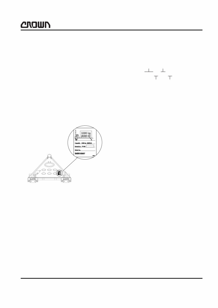
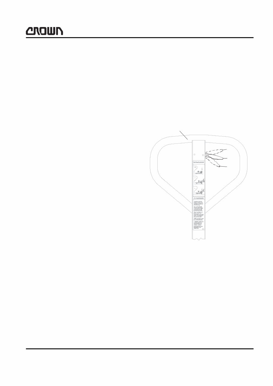
SERVICE Introduction 3 PTH50 Introduction This manual is intended for the service technician. It includes information about maintenance, trouble- shooting and a list of replacement parts for the hand pallet truck PTH50. Replacement Parts When ordering replacement parts from this manual, al- ways specify: – the part number – the model number of the truck – the serial number of the truck The data plate with model and serial number is located on the rear of the fork carriage (see Fig. 15292). Model Number This number is used as a brief description of the truck. Refer to the example below for the method used to de- termine the model number and its meaning. Lubrication The truck is designed to require minimum lubrication. Self-lubricating bushings and sealed bearings are used throughout the truck with two exceptions: – A single grease nipple is provided so the bear- ing in the traverse can occasionally be lubri- cated (use part number 063002-034). – The handle lever ball detent needs occasional lubrication (use part number 363108-001). 15292 1 Image Generator (PTH = Hand Pallet Truck) 2 Fork Spread (in inches) 3 Fork Length (in inches) 4 Capacity* [50 = 2300 kg (5000 lbs)] *Actual rated capacity may vary, depending on special equipment or modifications. Refer to the data plate for actual cpacity rating. PTH50-27-48 1 2 3 4
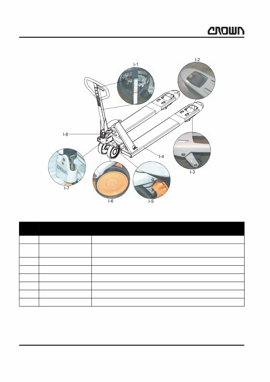
SERVICE Lubrication and Inspection 4 PTH50 Lubrication and Inspection 15310 Index Component Inspect / Lubricate I-1 Handle, Actuating Lever Inspect handle; lubricate handle detent ball area. I-2 Entry Roller, Load Roll- ers Check for cuts. I-3 Risers Keep risers lubricated. Check for signs of damage or wear. I-4 Forks Inspect forks for cracks on exterior surface. I-5 Grease Nipple Ensure bearing is properly lubricated; use part number 063002-034. I-6 Steered Wheels Inspect wheels for cuts. I-7 Hydraulic Unit Make sure pump is clean. Inspect for any signs of damage or wear. I-8 Spring Check spring for wear, damage, and cleanliness.
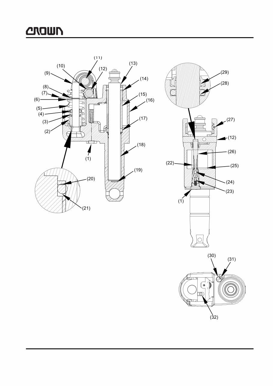
SERVICE Hydraulic Unit 5 PTH50 Hydraulic Unit Functions (Refer to Figures 15295 & 15305EU) Raise Raise function is selected by pushing actuating lever down to raise position (4, Fig. 15305EU). When the handle is raised, the pump piston is actuated upward by means of spring (5, Fig. 15295) and draws fluid from reservoir through control chamber, around the upper check ball (24) in the cartridge valve, through chamber (25) and into the pump cylinder. Fluid move- ment continues in this direction until the top of the han- dle stroke is reached. Pushing the handle downward forces fluid out of the pump cylinder and through the chamber. The upper check ball (24) in the cartridge valve blocks the control piston chamber and reservoir. This causes the fluid to continue past the lower check ball (23) in the cartridge valve and into lift chamber, moving the lift piston ram upward. The forks are raised. When the end of the handle stroke is reached, the han- dle is raised again and the cycle repeats. As the handle is raised, the lower check ball in the car- tridge valve (23) closes, thus retaining fluid in the lift chamber. Neutral Neutral function is selected by engaging actuating le- ver in neutral position (3, Fig. 15305EU). In this posi- tion tension is applied to the pull rod and chain. The chain pulls the connector and rotates the cam shaft moving the control piston downwards. The downward movement of the control piston unseats the upper check ball (24) in the cartridge valve in the control piston chamber. Raising the handle draws fluid from reservoir through control piston chamber around the upper check ball (24) in the cartridge valve through the control pis- ton chamber and into the pump cylinder. When the handle is pushed downwards, since the up- per check ball in the cartridge valve (24) is held un- seated, fluid returns to reservoir, by the same route. Lower Pulling the actuating lever up to lower position (2, Fig. 15305EU) lowers the forks. This transmits the downward movement of upper check ball (24) in the cartridge valve to the tappet and unseats the lower check ball (23) in the cartridge valve opening a pas- sageway and allowing fluid to escape from the lift chamber, back into the reservoir, thus lowering the lift piston ram and the forks. As the actuating lever is released, springs (5 & 22, Fig. 15305EU) and the spring in the handle return all components to their previous positions. Fluid Level With the forks lowered, check hydraulic fluid by un- screwing the filler plug. Insert a clean probe. • Maximum fluid level should be 38 mm (1.5 in) from top of pump cover. • Minimum level 57 mm (2.25 in) from top of pump cover. 15305EU 1 Handle 2 Actuating lever in lower position 3 Actuating lever in neutral position 4 Actuating lever in raise position 1 2 3 4
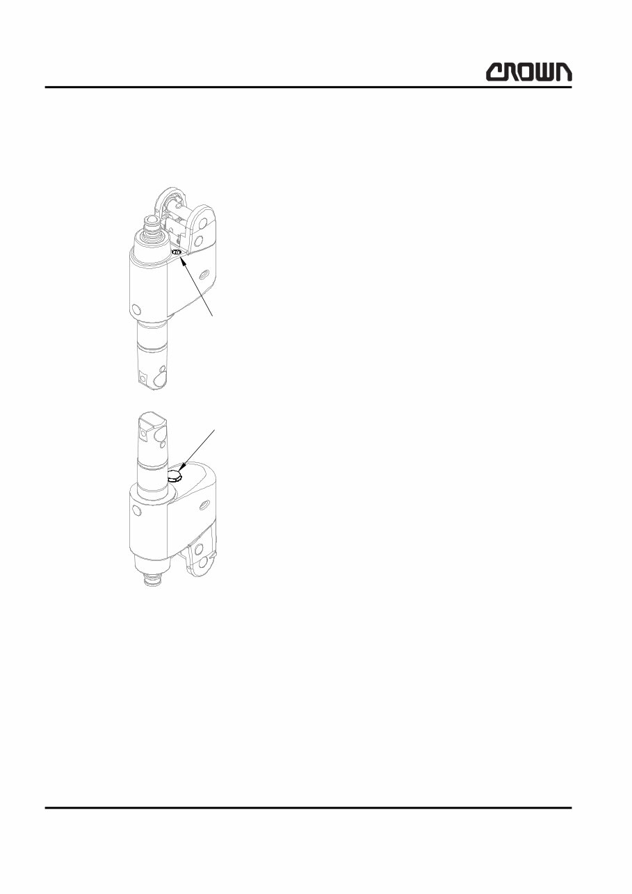
SERVICE Hydraulic Unit 6 PTH50 Capacity of the hydraulic unit is: • 46 mL (15.4 US fl oz) minimum • 58 mL (19.7 US fl oz) maximum Type of Fluid When operating in temperatures above freezing, use Crown anti-wear hydraulic fluid, part number 363504-101, or equal. For units being operated in tem- peratures below freezing, use Crown low temperature hydraulic fluid, part number 363505-101, or equal. Do not use brake fluid. To obtain maximum life from the hydraulic unit, a mag- net is located at the base of the ram to attract and hold any metal particles that could cause damage to seals, valve seats and other parts. Approximately every three months, the ram should be removed so that any parti- cles attracted to the magnet can be cleaned off. The hydraulic unit must be partially removed to remove the ram. Hydraulic Unit Removal (Refer to page 12) 1. Raise forks completely and securely block rear of truck approximately 100 mm (4.0 in). 2. Remove roll pin from frame. 3. Drive out roll pin. Remove hub caps & retaining rings. Remove wheels from axle. Remove retain- ing ring - not necessary for removal of ram to clean magnet. 4. Pull actuating lever to lower position, while press- ing lift piston ram into cylinder. The hydraulic unit can now be lifted out. 15283 Hydraulic Fluid Fill/Check Plug Cartridge Valve Torque to 50 Nm (36.8 ft lbs)
Crown PTH50 Series Hand Pallet Truck Service Repair and Parts Manual is an electronic manual that provides comprehensive information for the maintenance and repair of the Crown PTH50 Series Hand Pallet Truck. This manual is beneficial for both professional mechanics and DIY enthusiasts.
The manual covers a wide range of topics including replacement parts, model numbers, lubrication, functions, fluid levels, hydraulic unit removal, hydraulic unit disassembly, and troubleshooting. It also includes detailed information on the main frame, hydraulic unit, lift linkage, load roller (single and tandem), and load and decals.
Written in a step-by-step format, the manual is designed to make the repair process easy to understand and execute, potentially saving on expenses.
File Format: PDF
Compatibility: All Versions of Windows & Mac
Language: English
Requirements: Adobe Reader
Recently Viewed
5,521,897Happy Clients
2,594,462eManuals
1,120,453Trusted Sellers
15Years in Business
Price:
Actual Price:
Crown PTH50 Series Hand Pallet Truck Service Repair and Parts Manual INSTANT