

CLARK Forklift FACTORY Service Repair Manual
What's Included?
Fast Download Speeds
Online & Offline Access
Access PDF Contents & Bookmarks
Full Search Facility
Print one or all pages of your manual
Service
Manual
SM 591
GPH/DPH 50/60/70/75
Group 20
Drive Axle
Group 32
lilt Cylinders
Group 21
Prop Shaft
Group 06
Transmlsslon
Group 00
Group26/26
-!I
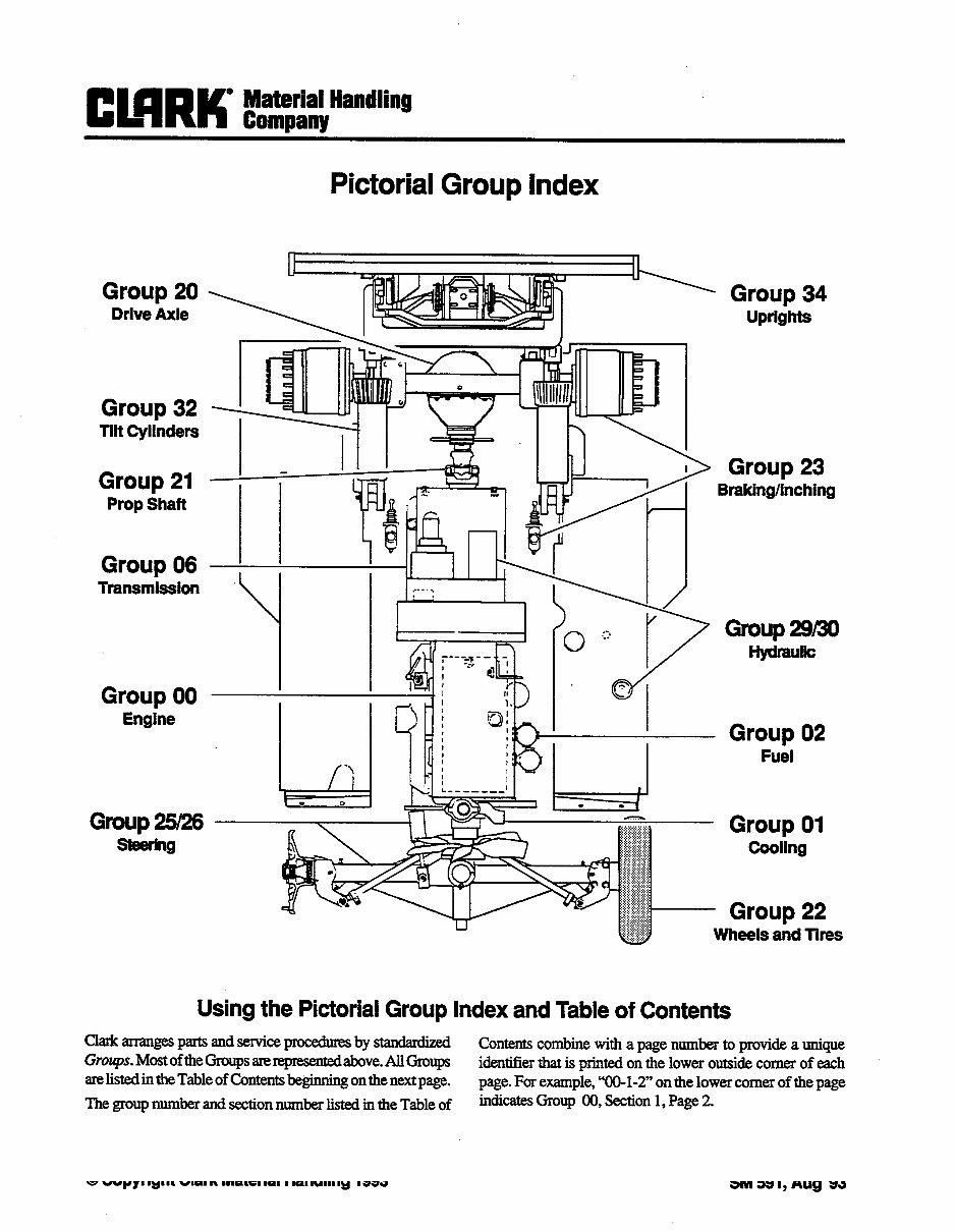
Pictorial Group Index
a_
Group 34
uprights
Group 23
Braklng/lnchlng
Group 29/30
Hydraulic
Group 02
Fuel
- Group 01
Cooling
- Group 22
Wheels and Tires
Using the PictorialGroup Index and Table of Contents
Clakinangespartsandserviceproceduresby~~
Contents combine with a page number to provide a unique
Gro~~~s.MostoftheGroupsarereprewWabove.AllGmups
identifierthat is printed on the lower outside comer of each
are listedin the Table of Contentsbeginningon the nextpage. page. For example,“00-1-2” on the lower comer of the page
The group number and section number listed in the Table of
indicatesGroup 00, Section 1, Page 2.
0 CopyrightClark Materlal Handling1993
SM 591, Aug ‘93
CONTENTS
Group#
00
00
al
00
00
00
01
01
01
01
01
02
02
02
02
02
06
06
06
06
06
06
14
14
14
14
14
20
20
20
20
20
20
20
20
Table of Contents
Section# Group/Section Name
INTRODUCTION
Safety
PlannedMaintenance
ENGINES
Engine Troubleshooting
Perkins Diesel Engine Workshop Manual
GM “Detroit” Diesel EngineWorkshop Manual
Ford Gas/LPG BngineWorkshop Manu
Engine Removal
COOLING SYSTEM
Cooling System Troubleshooting
Cooling System Testing and Maintenance
Fan Belt Replacement
Radiator Removal and Replacement
FUEL SYSTEM
Fuel System Troubleshooting
Air Induction System
The IMPCO Fuel System
Removal of IMPCO Vaporizing System
TRANSMISSION
Transmission Maintenance and Service Manual
Transmission Removal and Installation
Transmission Drain and Refill
Transmission Oil Cooler Checks
Neutral Start Switch
ELECTRICAL SYSTEM
wiring C&r C5de.s
ElectricalDiagrzns
BlectlicalChecks
StarterandAltemator
DRIVEAXLE
Drive Axle Description
Drive Axle Dissassembly
Drive Axle Assembly
Drive Axle Adjustment and Fastener Torque Values
Drive Axle Ends Disassembly and Assembly
Drive Axle Removal and Installation
Drive Axle Lubrication
(continued on next page)
SM 591, Aug ‘93 COIlbltS-1
Group#
21
21
22
22
22
22
22
23
23
23
23
23
23
23
23
25
25
25
25
26
26
26
26
26
26
29
29
29
29
30
30
30
30
30
30
32
32
32
32
section# Group/Section Name
1 Prop Shaf& Troubleshooting, Removal, and Service
1
2
3
1
2
3
1
2
3
PROP !sHAFr
WHEELSANDTIRES
Lifting, Jacking, and Blocking
Tire Removal and Mounting
Wheel Mounting
Towing
BRAKING/lNCHINGSYSTEM
System Description and Troubleshooting
Brake and Inching Pedal Adjustment
Brake and Inching System Bleeding
ServiceBrakeInqxctionandOverhaul
MasterCylin~
Hydrovac Overhaul
Parking Brake Adjustment
STEERING COLUMN AND GEAR
Steering SystemTroubleshooting
Steering Column and Gear Removal
Hydraguide Steering Control Unit
STEER AXLE
Steering System Checks and Adjustments
SteerAxle WheelBearings
Steer Axle Removal and Replacement
Steer Cylinder Removal and Replacement
SteerCylinder Overhaul
HYDRAuLIcsuMP,FJLTERs,ANDPuMP
Hydraulic Filters and Fluid Replacement
Hydraulic Pump Troubleshooting
HydraulicPumpOverhaul
HYDRAuLIccoNTRoLvALvE/LlFTcIRcurr
Hydraulic System Troubleshooting
Hydraulic SystemPressureQxck
Hydraulic Valve Owrhanl
Hydraulic Control Valve Linkage
Hydraulic Schematic
TILT CYLINDERS
Tilt Cylinder Removal and Replacement
Tilt Cylinder Overhaul
Tilt Lock Valve
Contents-2
SM 591, Aug ‘93
CONTENTS
Group # Section# Group/Section Name
34
34
34
34
34
34
34
34
38
38
40
40
40
40
40
40
40
1
1
2
3
4
5
6
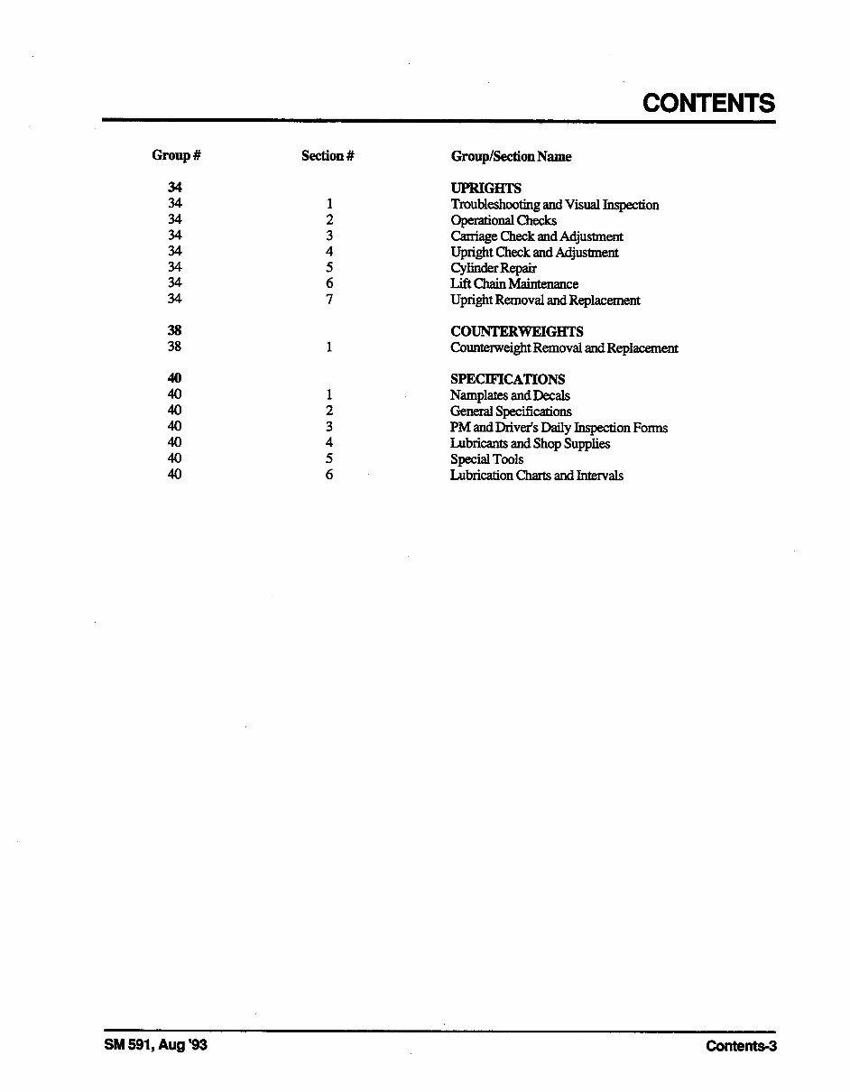
UPRIGHTS
Troubleshooting and Visual Iqection
OpltiOIldChtXkS
Carriage Check and Adjustment
Upright Check and Adjustment
Cylinder Repair
Lift ChainMaintenance
Upright Removal and Replacement
COUNTERWEIGHTS
Counterweight Removal and Replacement
SPEClFICATIONS
Namplates andDecals
GxxEralspecifications
PM and Driver’s Daily Inqection Forms
Lubricants and Shop Supplies
Special Tools
Lubrication charts and Intervals
SM 591, Aug ‘93 C43ntents-3
Emw
Introduction
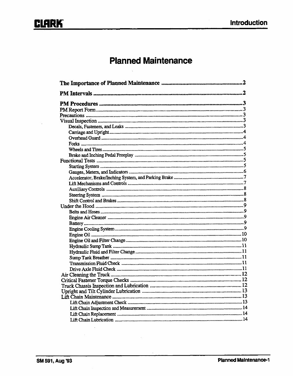
Planned Maintenance
The Importance of Planned Maintenance ......................................................... 2
PM Intervals .........................................................................................................
2
PM Procedures .....................................................................................................
3
PM Report Form ................................................................................................................
Precautions ........................................................................................................................
;
Visual Inspection ...............................................................................................................
3
Decals, Fasteners, and Leaks
................................................................................................... 3
Carriage and Upright
................................................................................................................ 4
Overhead Guard .......................................................................................................................
4
Forks ........................................................................................................................................
4
Wheels and Tires ......................................................................................................................
5
Brake and Inching Pedal Freeplay ...........................................................................................
Functional Tests
................................................................................................................ :
Starting System ........................................................................................................................
5
Gauges, Meters, and Indicators
................................................................................................ 6
Accelerator, Brake/Inching System, and Parking Brake
.......................................................... 7
Lift Mechanisms and Controls
................................................................................................. 7
Auxiliary Controls
................................................................................................................... 8
Steering System .......................................................................................................................
8
Shift Control and Brakes
..........................................................................................................
Under the Hood
................................................................................................................. ;
Belts and Hoses
........................................................................................................................ 9
Engine Air Cleaner
.................................................................................................................. 9
Battery
...................................................................................................................................... 9
Engine Cooling System
............................................................................................................ 9
Engine Gil ..............................................................................................................................
10
Engine Oil and Filter Change
................................................................................................. 10
Hydraulic Sump Tank
............................................................................................................ 11
Hydraulic Fluid and Filter Change ......................................................................................... 11
SumpTankBreather
.............................................................................................................. 11
Transmission Fluid Check
..................................................................................................... 11
Drive Axle Fluid Check .........................................................................................................
11
Air Cleaning the Truck ....................................................................................................
12
Critical Fastener Torque Checks
..................................................................................... 12
Truck Chassis Inspection and Lubrication ......................................................................
12
Upright and Tilt Cylinder Lubrication ............................................................................
13
Lift Chain Maintenance ...................................................................................................
13
Lift Chain Adjustment Check
................................................................................................ 13
Lift Chain Inspection and Measurement ................................................................................
14
Lift Chain Replacement ......................................................................................................... 14
Lift Chain Lubrication
........................................................................................................... 14
SM 591, Aug ‘93
PlannedMaintenance-1
Introduction
cl!!mK
The Importance of Planned
Maintenance
A planned maintenance (PM) program of regular,
routine inspections and lubrication is important for
long life and trouble-free operation of your lift truck.
Make and keep records of your inspections. Use
these records to help establish the correct PM inter-
vals for your application and to indicate maintenance
required to prevent major problems from occurring
during operation.
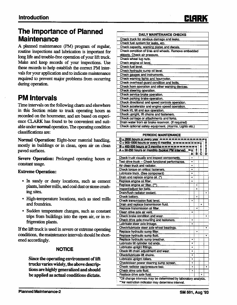
PM Intervals
Time intervals on the following charts and elsewhere
in this Section relate to truck operating hours as
recorded on the hometer, and ate based on experi-
ence CLARK has found to be convenient and suit-
able under normal operation. The operating condition
classifications are:
Normal Operation: Eight-hour material handling,
mostly in buikiings or in clean, open air on clean
paved surfaces.
Severe Operation: Prolonged operating hours or
constantusage.
Extreme Operation:
Jn sandy or dusty locations, such as cement
plants,lumbermills,andcoaldustorstonecrush-
ing sites.
H&h-temperature locations, such as steel mills
and foundries.
Sudden temperature changes, such as constant
trips from buildings into the open air, or in re-
frigeration plants.
If the lift truck is used in severe or extreme operating
conditions, the maintenance intervals shouldbe short-
ened accordingly.
NOTICE
Siucethe operating environment of lift
trucksvarieswidely,theabovedescrip-
tions are highly generalized and should
be applied as actual conditions dictate.
“*Air restriction indicator may determine interval.
PlannedMaintenance-2 SM 591, Aug ‘93
Introduction
PM Procedures
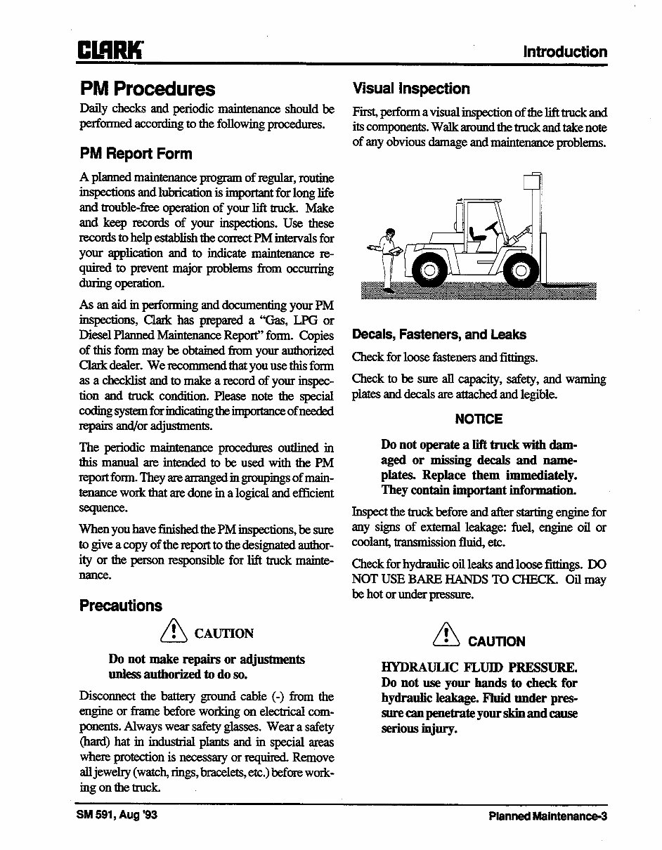
Visual Inspection
Daily checks and periodic maintenance should be
performed according to the following procedures.
PM Report Form
First, perform a visual inspection of the lift truck and
its components. Walk around the truck and take note
of any obvious damage andmaintenance problems.
A planned maintenance program of regular, routine
inspections and lubrication is important for long life
and trouble-free operation of your lift truck. Make
and keep records of your inspections. Use these
records to help establish the correct PM intervals for
your application and to indicate maintenance re-
quired to prevent major problems from occuning
during operation.
As an aid in performing and documenting your PM
inspections, Clark has prepared a “Gas, LPG or
Diesel Planned Maintenance Report” form. Copies
of this form may be obtained from your authorized
Clark dealer. We recommend that you use this form
as a checklist and to make a record of your inspec-
tion and truck condition. Please note the special
codingsystemforindicatingtheimportanceofneeded
repairs and/or adjustments.
The periodic maintenance procedures outlined in
thismanualateintendedtobeusedwiththePM
report form. They are arranged in groupings of main-
tenance work that are done in a logical and efficient
sequence.
Decals, Fasteners, and Leaks
Check for loose fasteners and fittings.
Check to be sure all capacity, safety, and warning
plates and decals are attached and legible.
NOTICE
Do not operate a lift truck with dam-
aged or missing decals and name-
plates. Replace them immediately.
They contain important iuformatio~~
When you have finished the PM inspections, be sure
to give a copy of the report to the designated author-
ity or the person responsible for lift truck mainte-
nance.
Inspect the truck before and after starting engine for
any signs of extemal leakage: fuel, engine oil or
coolant, transmission fluid, etc.
Precautions
/\
! CAUTION
Do not make repairs or adjustments
unless authorized to do so.
Check for hydraulic oil leaks and loose fittings. DO
NOT USE BARE HANDS TO CHECK. Oil may
be hot or under pressure.
A ! CAUTION
Disconnect the battery ground cable (-) from the
engine or frame before working on electrical com-
ponents. Always wear safety glasses. Wear a safety
(hard) hat in industrial plants and in special areas
where protection is necessary or required Remove
all jewehy (watch rings, bracelets, etc.) before work-
ing on the truck
HYDRAULIC FLUID PREssuRE.
Do not use your hands to check for
hydraulic leakage. Fluid under pres-
surecaupenetrateyourskinandcause
serious injury.
SM 591, Aug ‘93 PlannedMaintenance-3
Introduction
el!!mK
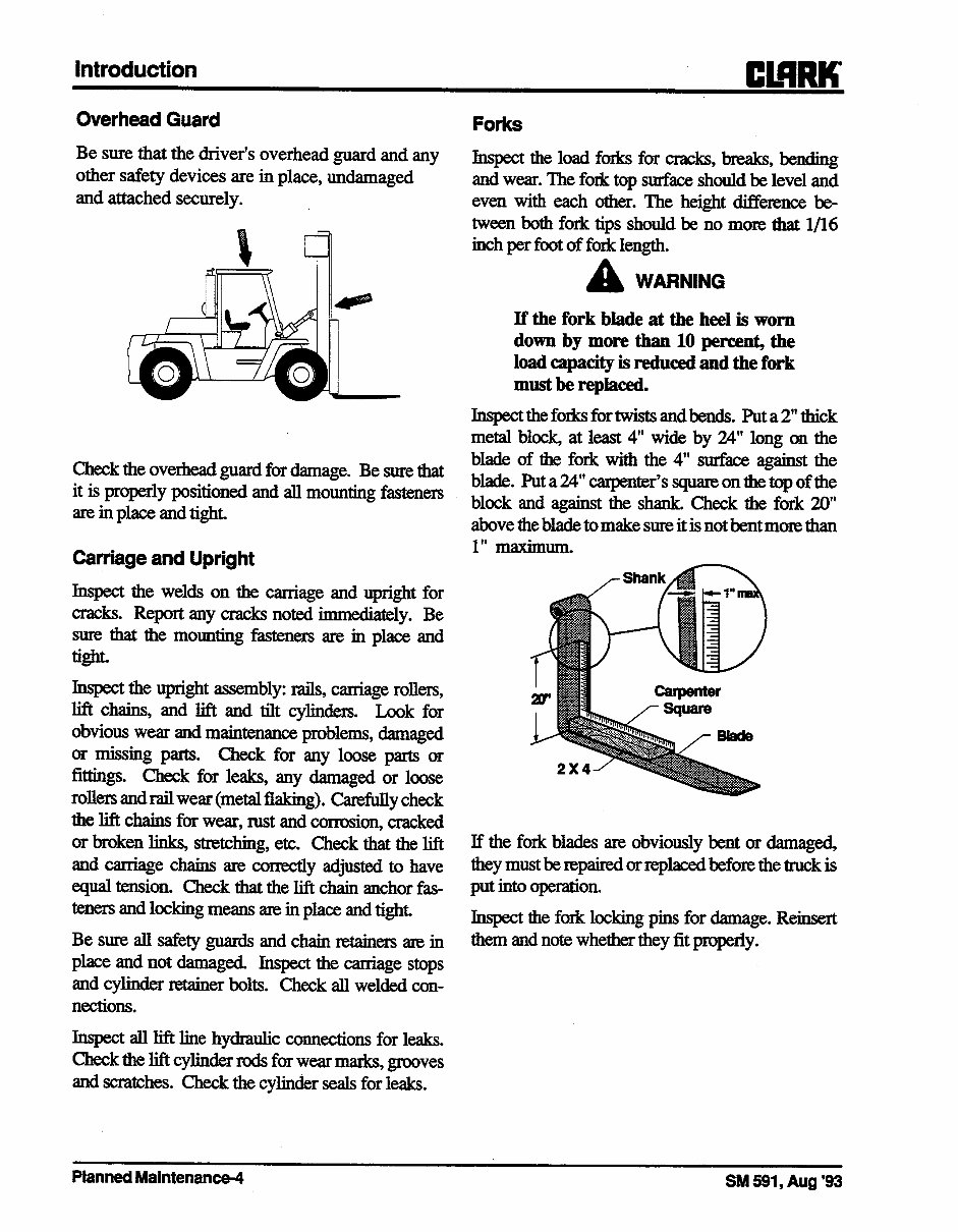
OverheadGuard
Forks
Be sure that the driver’s overhead guard and any
other safety devices are in place, undamaged
and attached securely.
Inspectthe load forks for cracks, breaks, bending
and wear. The fork top surface should be level and
even with each other. The height difference be-
tween both fork tips should be no more that l/16
inch per foot of fork length.
Check the overhead guard for damage. Be sure that
it is properly positioned and all mounting fasteners
are in place and tight.
Carriageand Upright
Inspect the welds on the carriage and upright for
cracks. Report any cracks noted immediately. Be
sum that the mounting fasteners are in place and
tight.
Inspect the upright assembly: rails, carriage rollers,
lift chains, and lift and tilt cylinders. Look for
obvious wear and maintenance problems, damaged
or missing parts. Check for any loose parts or
fittings. Check for leaks, any damaged or loose
rollers and rail wear (metal flaking). Carefully check
the lift chains for wear, rust and corrosion, cracked
or broken links, stretching, etc. Check that the hft
and carriage chains are cornxtly adjusted to have
equal tension. Check that the lift chain anchor fas-
teners and locking means are in place and tight
Besureallsafetyguardsandchainretainersamin
place and not damaged. Jnspect the carriage stops
and cylinder retainer bolts. Check all welded con-
nections.
Jnspect all lift line hydraulic connections for leaks.
Check the lift cylinder rods for wear marks, grooves
and scratches. Check the cylinder seals for leaks.
A
WARNING
If the fork blade at the heel is worn
down by more than 10 percent, the
load capacity is reduced and the fork
must be replaced.
Inspecttheforksfortwistsandbends. Puta2”thick
metal block, at least 4” wide by 24” long on the
blade of the fork with the 4” surface against the
blade. Put a 24” carpenter’s square on the top of the
block and against the shank. Check the fork 20”
above the blade to make sure it is not bent more than
1” maximum.
If the fork blades ate obviously bent or damaged,
they mustbetepairedorreplacedbefore the track is
put into operation.
Inspect the fork locking pins for damage. Reinsert
them and note whether they fit properly.
PlannedMaintenance-rl
SM 591, Aug ‘93
Introduction
Wheels and Tires
Check the condition of the drive and steer wheels
and tires. Remove objects that ate embedded in the
tread. Inspect the tires for excessive wear or breaks
or “chunking out”.
Check all wheel lug nuts or bolts to be sure none are
loose or missing. Have missing bolts or lug nuts
replaced and tightened to correct torque before
opemting truck (See ‘Torque Specifications” in
Group 40.)
A
WARNING
Check tire pressure from a position
facing the tread of the tire, not the side.
Use a long handled gauge to keep your
body away from the side. If tires are
low, do not add air. Check with a
mechanic. The tire may require re-
moval and repair. Incorrect (low) tire
pressure can reduce stability of your
lift truck. See Group 40, Section 2,
T@ecification,” for proper inflation
Pm
Brake and Inching Pedal Freeplay
Pxessdownonthebrakepedalwithyourhandto
check for &play. The freeplay should be approxi-
mately 0.31 inch (8mm). Adjust fieeplay as de-
scribed in Group 23, if necessary.
checkinchingpedalfreeplayaswiththebrakepedal,
and adjust if necessary.
Functional Tests
Besurethat:
l Parking brake is applied.
l Directional control is in ‘W’ (neutral).
Test the horn, lights and all other safety equipment
and accessories. Be sure they are properly mounted
and working correctly.
Press the horn button to check horn function. If the
horn or any other part does not operate, report the
faihu-e and have it repaired before the truck is put in
operation.
Now prepare to start the truck so that you can test
gauges, accelerator service and parking brakes, all
hydraulic controls, directional controls, and steering
system. All controls must operate freely and return
to neutral properly.
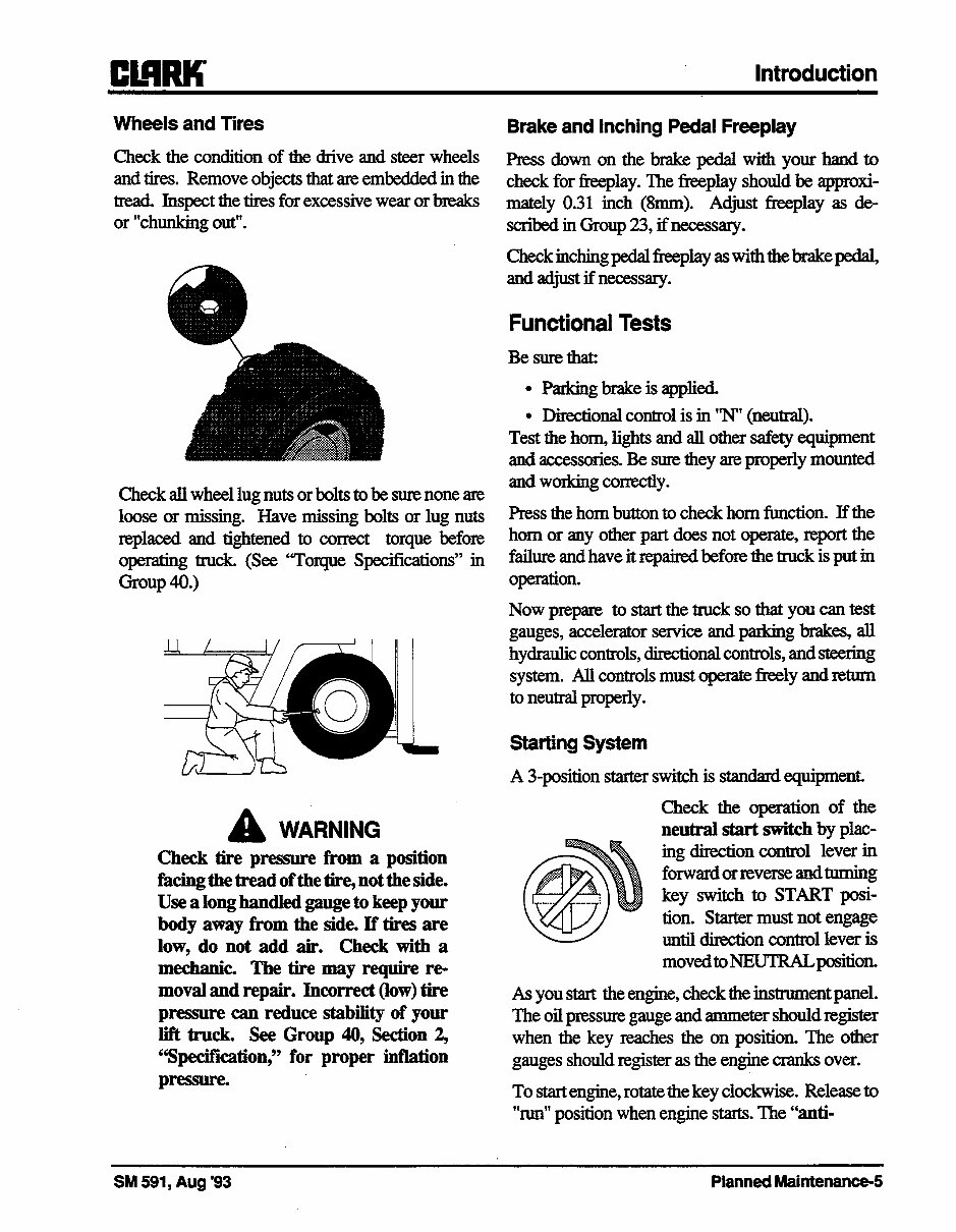
Starting System
A 3position starter switch is standard equipment.
Check the operation of the
neutral start switch by plac-
ing direction control lever in
forwardorreverseandturning
key switch to START posi-
tion. Starter must not engage
until dim&ion control lever is
movedtoNEUTRALposition.
As you start the engine, check the instrument panel.
The oil pressure gauge and ammeter should register
when the key reaches the on position. The other
gauges should register as the engine cranks over.
To start engine, rotate the key clockwise. Release to
“run” position when engine starts. The “anti-
SM 591, Aug ‘93 PlannedMaintenance-5
You're Reading a Preview
What's Included?
Fast Download Speeds
Online & Offline Access
Access PDF Contents & Bookmarks
Full Search Facility
Print one or all pages of your manual
$39.99
Viewed 35 Times Today


Secure transaction
What's Included?
Fast Download Speeds
Online & Offline Access
Access PDF Contents & Bookmarks
Full Search Facility
Print one or all pages of your manual
$39.99
The Clark forklift repair manual covers GPH/DPH 50 60 70 75 models and addresses most repair and service issues for these forklifts. Whether you are a professional mechanic or a DIY enthusiast, this manual provides comprehensive guidance for maintenance and repairs, allowing you to save money by doing it yourself. It is compatible with both Mac and PC computers, ensuring fast access to the information you need.


