Contents General information GEN INFO 0 Specification SPEC 1 Technical feature and description TECH FEA 2 Rigging information RIG GING 3 Troubleshooting TRBL SHTG 4 Electrical system ELEC 5 Digital Electronic Control unit DIGIT CONT 6 Index Appendix A
GEN INFO 0 1 2 3 4 5 6 7 8 9 10 A General information 0 Safety while working .................................................... 0-1 Rotating part .............................................................................. 0-1 Hot part ...................................................................................... 0-1 Electric shock ............................................................................ 0-1 Handling of gasoline .................................................................. 0-1 Ventilation .................................................................................. 0-1 Self-protection ........................................................................... 0-2 Working with crane .................................................................... 0-2 Part, lubricant, and sealant ........................................................ 0-2 Handling of sealant .................................................................... 0-2 Special service tool ................................................................... 0-2 Tightening torque ...................................................................... 0-3 Non-reusable part ...................................................................... 0-3 Disassembly and assembly ....................................................... 0-3 How to use this manual .................................................... 0-4 Manual format ........................................................................... 0-4 Abbreviation .............................................................................. 0-5 Lubricant, sealant, and thread locking agent ................. 0-6 Symbol ...................................................................................... 0-6 Special service tool ........................................................... 0-7
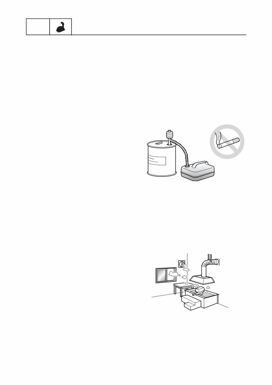
0-1 GEN INFO General information Safety while working To prevent an accident or injury and to pro- vide quality service, observe the following safety procedures. Rotating part • Hands, feet, hair, jewelry, clothing, personal flotation device straps, and so on, can become entangled with internal rotating parts of the engine, resulting in serious injury or death. • Keep the top cowling installed whenever possible. Do not remove or install the top cowling when the engine is running. • Only operate the engine with the top cowl- ing removed according to the specific instructions in the manual. Keep hands, feet, hair, jewelry, clothing, personal flota- tion device straps, and so on, away from any exposed moving parts. Hot part During and after operation, engine parts are hot enough to cause burns. Do not touch any parts under the top cowling until the engine has cooled. Electric shock Do not touch any electrical parts while start- ing or operating the engine. Otherwise, shock or electrocution could result. Handling of gasoline • Gasoline is highly flammable. Keep gaso- line and all flammable products away from heat, sparks, and open flames. • Gasoline is poisonous and can cause injury or death. Handle gasoline with care. Never siphon gasoline by mouth. If you swallow some gasoline, inhale a lot of gasoline vapor, or get some gasoline in your eyes, see your doctor immediately. If gasoline spills on your skin, wash with soap and water. If gasoline spills on your clothing, change your clothes. Ventilation • Gasoline vapor and exhaust gas are heavier than air and extremely poisonous. If gasoline vapor or exhaust gas is inhaled in large quantities, it may cause loss of con- sciousness and death within a short time. • When test running an engine indoors (for example, in a water tank) make sure to do so where adequate ventilation can be main- tained.
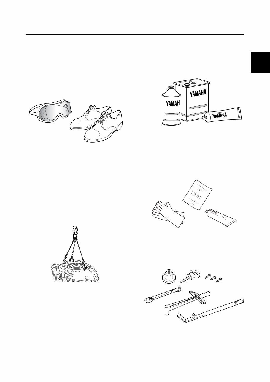
0-2 Safety while working 0 1 2 3 4 5 6 7 8 9 10 A Self-protection • Protect your eyes by wearing safety glasses or safety goggles during all opera- tions involving drilling and grinding, or when using an air compressor. • Protect your hands and feet by wearing pro- tective gloves and safety shoes when nec- essary. Working with crane • Outboard motors weighing 18.0 kg (39.7 lb) and over must be carried by a crane. • Use the wire ropes of adequate strength, and lift up the outboard motor using the three-point suspension. • If the outboard motor does not have three or more points to be suspended, support it using additional ropes, or the like, so that the outboard motor can be lifted and carried in a stable manner. Part, lubricant, and sealant Use only genuine Yamaha parts, lubricants, and sealants, or those recommended by Yamaha, when servicing or repairing the out- board motor. Handling of sealant • Wear protective gloves to protect your skin, when using the sealants. • See the material safety data sheet issued by the manufacturer. Some of the sealants may be harmful to human health. Special service tool Use the recommended special service tools to work safely, and to protect parts from dam- age.
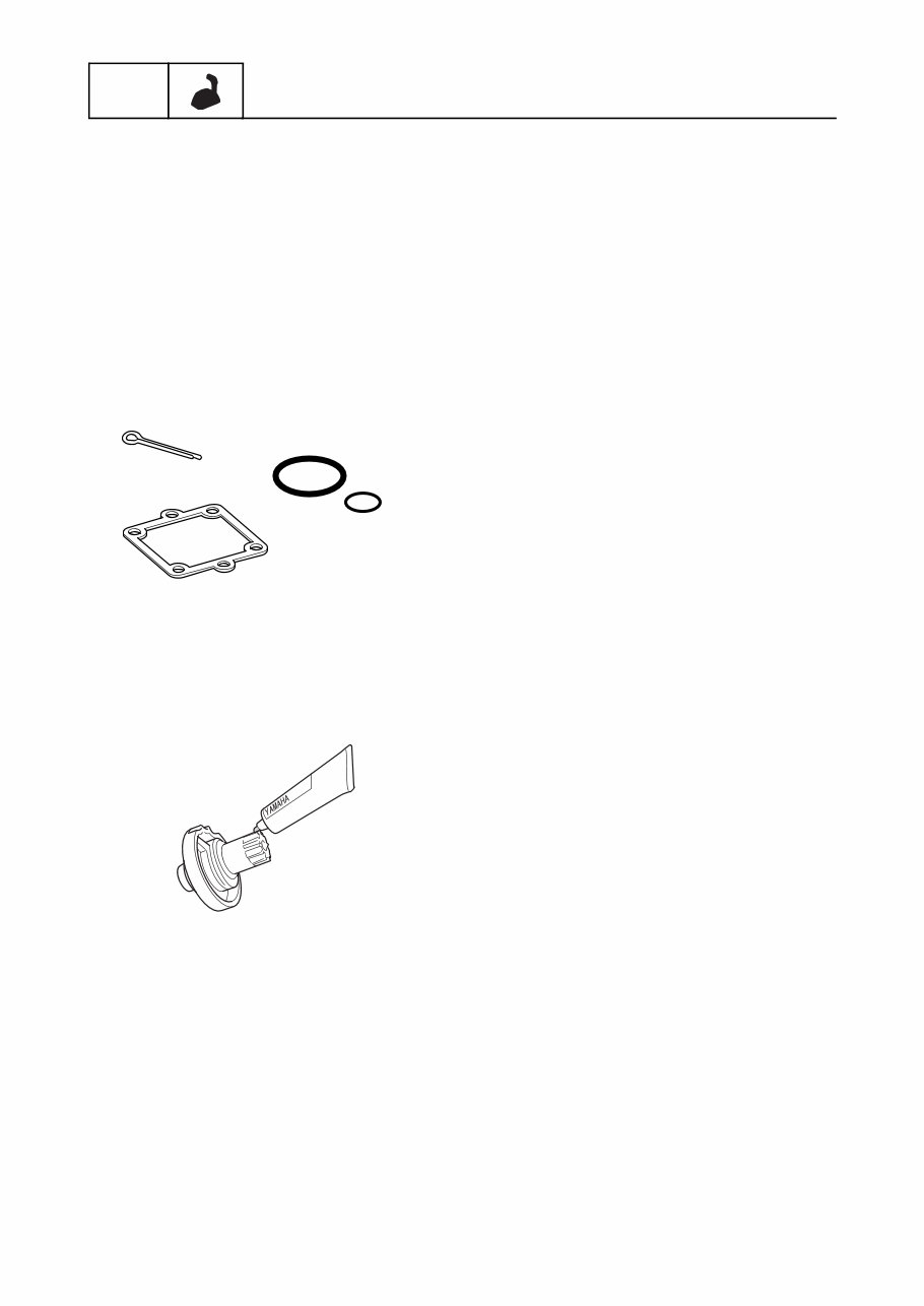
0-3 GEN INFO General information Tightening torque When tightening nuts, bolts, and screws, fol- low the tightening instructions provided throughout the manual. If the tightening order is not specified, tighten the large sizes first, and then tighten the small sizes, starting from the center and moving outward. Non-reusable part Always use new gaskets, seals, O-rings, cot- ter pins, and so on, when installing or assem- bling parts. Disassembly and assembly • Use compressed air to remove dust and dirt during disassembly. • Apply specified grease to the contact sur- faces of moving parts before assembly. • Check that moving parts operate normally after assembly.
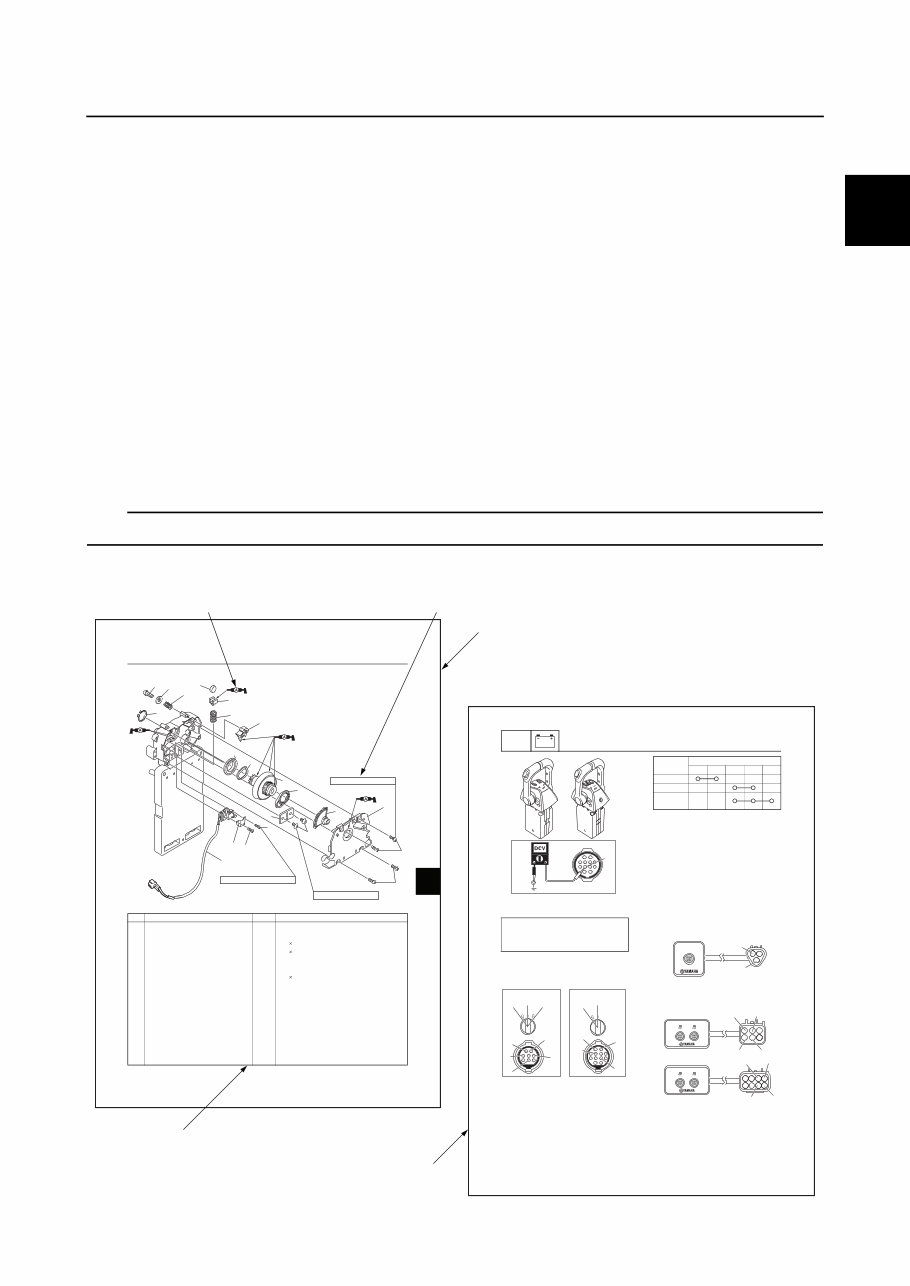
0-4 0 1 2 3 4 5 6 7 8 9 10 A How to use this manual Manual format The format of this manual has been designed to make service procedures clear and easy to under- stand. Use the following information as a guide for effective and quality service. • Parts are shown and detailed in an exploded diagram and are listed in the component list (see a in the following figure for an example page). • The component list consists of part names and quantities, as well as bolt and screw dimensions (see b in the following figure). • Symbols are used to indicate important aspects of a procedure, such as the grade of lubricant and the lubrication points (see c in the following figure). • Tightening torque specifications are provided in the exploded diagrams (see d in the following fig- ure), and in the related detailed instructions. Some torque specifications are listed in stages as torque figures or angles in degrees. • Separate procedures and illustrations are used to explain the details of removal, checking, and installation where necessary (see e in the following figure for an example page). TIP: For troubleshooting procedures, see Chapter 4, “Troubleshooting.” 5-51 ELEC Electrical system A Single engine type B Twin and triple engine types 3. Check the engine start switch or main switch for continuity at the engine start switch coupler. A Engine start switch B Main switch (*1) Engine start switch only 4. Connect the engine start switch or main switch coupler. Checking the engine start/stop button 1. Disconnect the engine start/stop button coupler. 2. Check the engine start/stop button for continuity at the engine start/stop button coupler. Engine start switch or main switch input voltage: Red (R)–Ground 12.0 V (battery voltage) B R b a a B b e A c d c d OFF START ON ON OFF Switch position Terminal a b c d e OFF ON START (*1) a b A B C d c e f d c e f 6-4 0 1 2 3 4 5 6 7 8 9 10 A Gear housing (single engine type [top mount]) s k r a m e R y t ’ Q e m a n t r a P . o N 1 h c t i w s l a r t u e N 1 1 e t a l P 2 3 M 2 w e r c s h c t i w s l a r t u e N 3 10 mm 5 M 4 w e r c s g n i s u o h r a e R 4 14 mm 1 g n i s u o h r a e R 5 1 r a e G 6 5 M 2 w e r c s r e n i a t e R 7 10 mm 1 m r a e v i r D 8 1 t f a h s e v i r D 9 1 e t a l p n o i t c i r F 0 1 1 g n i r p S 1 1 1 r e t p a d A 2 1 1 r e l l o R 3 1 1 g n i r p S 4 1 1 r e h s a W 5 1 1 t l o B 6 1 1 p i l c r i C 7 1 0.4 N·m (0.04 kgf·m, 0.30 ft·lb) 3 N·m (0.3 kgf·m, 2.2 ft·lb) 3 N·m (0.3 kgf·m, 2.2 ft·lb) 1 2 3 3 4 4 5 6 7 8 9 20 10 11 12 13 14 15 16 17 18 19 ECM housing (single engine type [top mount]) / Gear housing (single engine type [top mount]) e b c d a Safety while working / How to use this manual
0-5 GEN INFO General information Abbreviation The following abbreviations are used in this service manual. Abbreviation Description ABYC American Boat and Yacht Council CAN Controller Area Network DN Down side ECM Electronic Control Module Eng Engine EUR Europe EXH Exhaust F Forward GPS Global Positioning System ID Identification INT Intake LAN Local Area Network LED Light Emitting Diode LPS Lever Position Sensor Max. Maximum Mfg./Dlr Manufacturer/Dealer Min. Minimum N Neutral NMEA National Marine Electronics Association OCV Oil Control Valve PORT Port side PTT Power Trim and Tilt R Reverse R/C Remote Control (Digital Electronic Control) SPS Shift Position Sensor STBD Starboard side Temp Temperature UP Up side YDIS Yamaha Diagnostic System
This manual is a comprehensive guide for servicing and rigging Yamaha Command Link Plus Systems, including DEC Remote Controls, Multi-Display, Y-COP, Multisensor, AGI, and Gateway Command Link Plus Systems. It is applicable to models manufactured from April 2010 onwards. Whether you are a professional mechanic or a DIY enthusiast, this factory service manual contains detailed procedures for all aspects of the outboard motor.
The manual presents information in a sequential, step-by-step format, making it easy to follow. It serves as a valuable reference, offering thorough explanations of disassembly, repair, assembly, and inspection operations. Each chapter is accompanied by exploded diagrams before the disassembly section, aiding in the identification of correct procedures for disassembly and assembly.
Recently Viewed
5,521,897Happy Clients
2,594,462eManuals
1,120,453Trusted Sellers
15Years in Business
Price:
Actual Price:
Yamaha outboard service manual Command Link Plus Systems - DEC Remote Controls, Multi-Display, Y-COP, Multisensor, AGI, Gateway