

Yamaha Jet Drive Operation & Service Manual Jet Drive Operation & Service Manual - Four Stroke EFI Models
What's Included?
Fast Download Speeds
Online & Offline Access
Access PDF Contents & Bookmarks
Full Search Facility
Print one or all pages of your manual
Operation and Service Manual
Four-Stroke
JET DRIVE

Four-Stroke Jet Drive Operation and Service Manual
©2002 by Yamaha Motor Corporation, U.S.A.
September 2002
All rights reserved. Any reprinting
or unauthorized use
without written permission of
Yamaha Motor Corporation, U.S.A.
is expressly prohibited.
Printed in U.S.A.
Specifications, features and options are subject to
change without notice.
02-467

TABLE OF CONTENTS
INTRODUCTION . . . . . . . . . . . . . . . . . . . . . . . . . . . . . . . . . . . . . . . . . . . . . . . . . . . . . . . . . . . . 1
FEATURES AND ADVANTAGES . . . . . . . . . . . . . . . . . . . . . . . . . . . . . . . . . . . . . . . . . . . . . . . . . . . . . . 2
LOCATION OF MAIN COMPONENTS . . . . . . . . . . . . . . . . . . . . . . . . . . . . . . . . . . . . . . . . . . . . . . . . . . 2
MODEL IDENTIFICATION AND SERIAL NUMBERS . . . . . . . . . . . . . . . . . . . . . . . . . . . . . . . . . . . . . . . 3
ENGINE MOUNTING . . . . . . . . . . . . . . . . . . . . . . . . . . . . . . . . . . . . . . . . . . . . . . . . . . . . . . . . . . . . . . . 4
MOUNTING HEIGHT . . . . . . . . . . . . . . . . . . . . . . . . . . . . . . . . . . . . . . . . . . . . . . . . . . . . . . . . . . . . 4
TEST RUNNING . . . . . . . . . . . . . . . . . . . . . . . . . . . . . . . . . . . . . . . . . . . . . . . . . . . . . . . . . . . . . . . . 4
TRANSOM ELEVATORS . . . . . . . . . . . . . . . . . . . . . . . . . . . . . . . . . . . . . . . . . . . . . . . . . . . . . . . . . 4
ANTI-CAVITATION PLATES . . . . . . . . . . . . . . . . . . . . . . . . . . . . . . . . . . . . . . . . . . . . . . . . . . . . . . . 4
OPERATING INSTRUCTIONS . . . . . . . . . . . . . . . . . . . . . . . . . . . . . . . . . . . . . . . . . . . . . . . . . . . . . . . . 6
SHIFTING . . . . . . . . . . . . . . . . . . . . . . . . . . . . . . . . . . . . . . . . . . . . . . . . . . . . . . . . . . . . . . . . . . . . 6
REMOTE CONTROL . . . . . . . . . . . . . . . . . . . . . . . . . . . . . . . . . . . . . . . . . . . . . . . . . . . . . . . . . . . . 6
STEERING . . . . . . . . . . . . . . . . . . . . . . . . . . . . . . . . . . . . . . . . . . . . . . . . . . . . . . . . . . . . . . . . . . . . 6
SHALLOW WATER OPERATION . . . . . . . . . . . . . . . . . . . . . . . . . . . . . . . . . . . . . . . . . . . . . . . . . . . 6
INTAKE BLOCKAGE . . . . . . . . . . . . . . . . . . . . . . . . . . . . . . . . . . . . . . . . . . . . . . . . . . . . . . . . . . . . 8
MOORING . . . . . . . . . . . . . . . . . . . . . . . . . . . . . . . . . . . . . . . . . . . . . . . . . . . . . . . . . . . . . . . . . . . . 8
THROTTLE USE . . . . . . . . . . . . . . . . . . . . . . . . . . . . . . . . . . . . . . . . . . . . . . . . . . . . . . . . . . . . . . . 8
TILT AND TRIM USE . . . . . . . . . . . . . . . . . . . . . . . . . . . . . . . . . . . . . . . . . . . . . . . . . . . . . . . . . . . . 8
MAINTENANCE, LUBRICATION, AND STORAGE . . . . . . . . . . . . . . . . . . . . . . . . . . . . . . . . . . . . . . . . 8
GENERAL . . . . . . . . . . . . . . . . . . . . . . . . . . . . . . . . . . . . . . . . . . . . . . . . . . . . . . . . . . . . . . . . . . . . 8
BEARING LUBRICATION . . . . . . . . . . . . . . . . . . . . . . . . . . . . . . . . . . . . . . . . . . . . . . . . . . . . . . . . . 8
IMPELLER CLEARANCE SETTING . . . . . . . . . . . . . . . . . . . . . . . . . . . . . . . . . . . . . . . . . . . . . . . . . 8
LINKAGE ADJUSTMENT . . . . . . . . . . . . . . . . . . . . . . . . . . . . . . . . . . . . . . . . . . . . . . . . . . . . . . . . . 8
SALT WATER OPERATION . . . . . . . . . . . . . . . . . . . . . . . . . . . . . . . . . . . . . . . . . . . . . . . . . . . . . . . 8
STORAGE . . . . . . . . . . . . . . . . . . . . . . . . . . . . . . . . . . . . . . . . . . . . . . . . . . . . . . . . . . . . . . . . . . . . 9
ADJUSTMENTS . . . . . . . . . . . . . . . . . . . . . . . . . . . . . . . . . . . . . . . . . . . . . . . . . . . . . . . . . . . . . . . . . . 9
SHIFT CAM ASSEMBLY WITH NEUTRAL ADJUSTMENT . . . . . . . . . . . . . . . . . . . . . . . . . . . . . . . . 9
NEUTRAL ADJUSTMENT OF ALL MODELS . . . . . . . . . . . . . . . . . . . . . . . . . . . . . . . . . . . . . . . . . . . 9
TRIM . . . . . . . . . . . . . . . . . . . . . . . . . . . . . . . . . . . . . . . . . . . . . . . . . . . . . . . . . . . . . . . . . . . . . .10
IDLE . . . . . . . . . . . . . . . . . . . . . . . . . . . . . . . . . . . . . . . . . . . . . . . . . . . . . . . . . . . . . . . . . . . . . .10
PERFORMANCE TIPS . . . . . . . . . . . . . . . . . . . . . . . . . . . . . . . . . . . . . . . . . . . . . . . . . . . . . . . . . . 10
OVERHAUL PROCEDURES . . . . . . . . . . . . . . . . . . . . . . . . . . . . . . . . . . . . . . . . . . . . . . . . . . . . . . . . 11
F40MJH & F40EJR (F40) 4-STROKE 3-CYLINDER
PARTS LIST . . . . . . . . . . . . . . . . . . . . . . . . . . . . . . . . . . . . . . . . . . . . . . . . . . . . . . . . . . . . . . . . . . 14
ASSEMBLY INSTRUCTIONS . . . . . . . . . . . . . . . . . . . . . . . . . . . . . . . . . . . . . . . . . . . . . . . . . . . . . 16
TILLER STEERING SHIFT CABLE PARTS LIST . . . . . . . . . . . . . . . . . . . . . . . . . . . . . . . . . . . . . . . 18
TILLER STEERING SHIFT CABLE ASSEMBLY . . . . . . . . . . . . . . . . . . . . . . . . . . . . . . . . . . . . . . . 19
F60 4-STROKE 4-CYLINDER
PARTS LIST . . . . . . . . . . . . . . . . . . . . . . . . . . . . . . . . . . . . . . . . . . . . . . . . . . . . . . . . . . . . . . . . . . 20
ASSEMBLY INSTRUCTIONS . . . . . . . . . . . . . . . . . . . . . . . . . . . . . . . . . . . . . . . . . . . . . . . . . . . . . 22
TILLER STEERING SHIFT CABLE PARTS LIST . . . . . . . . . . . . . . . . . . . . . . . . . . . . . . . . . . . . . . . 24
TILLER STEERING SHIFT CABLE ASSEMBLY . . . . . . . . . . . . . . . . . . . . . . . . . . . . . . . . . . . . . . . 25
F90 4-STROKE 4-CYLINDER
PARTS LIST . . . . . . . . . . . . . . . . . . . . . . . . . . . . . . . . . . . . . . . . . . . . . . . . . . . . . . . . . . . . . . . . . . 26
ASSEMBLY INSTRUCTIONS . . . . . . . . . . . . . . . . . . . . . . . . . . . . . . . . . . . . . . . . . . . . . . . . . . . . . 28

TILLER STEERING SHIFT CABLE PARTS LIST . . . . . . . . . . . . . . . . . . . . . . . . . . . . . . . . . . . . . . . 30
TILLER STEERING SHIFT CABLE ASSEMBLY . . . . . . . . . . . . . . . . . . . . . . . . . . . . . . . . . . . . . . . 31
F115 4-STROKE 4-CYLINDER
PARTS LIST . . . . . . . . . . . . . . . . . . . . . . . . . . . . . . . . . . . . . . . . . . . . . . . . . . . . . . . . . . . . . . . . . . 26
ASSEMBLY INSTRUCTIONS . . . . . . . . . . . . . . . . . . . . . . . . . . . . . . . . . . . . . . . . . . . . . . . . . . . . . 28
SPECIFICATIONS . . . . . . . . . . . . . . . . . . . . . . . . . . . . . . . . . . . . . . . . . . . . . . . . . . . . . . . . . . . . . . . . 37
LIMITED WARRANTY . . . . . . . . . . . . . . . . . . . . . . . . . . . . . . . . . . . . . . . . . . . . . . . . . . . . . . . . . . . . . 39
TILLER HANDLE TEMPLATES . . . . . . . . . . . . . . . . . . . . . . . . . . . . . . . . . . . . . . . . . . . . . . . . . . . . . . 41

1
INTRODUCTION
This Four-Stroke Jet Drive Operation and Service Manual is designed to be used in conjunction
with your Yamaha Outboard Motor Owner’s and Service Manuals. It contains operating instructions
as well as service and maintenance information that applies specifically to Yamaha Jet Drives.
Refer to your Outboard Owner’s and Service Manuals regarding general operating and service
information.
The related Outboard Owner’s and Service Manuals refer to horsepower rating for Yamaha’s pro-
peller-driven models. The actual performance output of Yamaha’s Jet Drive models cannot be pos-
itively rated because the output varies with type of hull, load, forward speed, and the angle of
planing achieved. Generally, the industry standard for determining the performance level of a jet-
driven outboard is that its output is approximately 70% of that of a propeller-driven unit with the
same powerhead.
This Operation and Service Manual covers several Yamaha Jet Drive models. Where there are
model-year differences, references are made to applicable models. In addition, references are
made throughout the manual to the model designation (which includes the engine’s prop-shaft mod-
el horsepower) or to the engine’s configuration. The following chart explains the corresponding des-
ignations:
4-Stroke
Read both this manual and your Outboard Motor manual before attempting to put your Yamaha Jet
Drive Outboard Motor into service. You should be familiar with all the control positions, and know
where each control is set during operation.
Engine Horsepower Jet Drive Model
Model Designation Engine Configuration Designation
F40 3-cylinder 30
F60 4-cylinder 40
F90 4-cylinder 65
F115 4-cylinder 80
FEATURES AND ADVANTAGES
Your Yamaha Jet Drive Outboard Motor was
specifically designed to allow boating in loca-
tions where a propeller-driven craft is unable to
operate, such as in ankle-deep water, white-
water rapids, over sand bars, shoals, etc.
Because there is no propeller housing extend-
ing below the hull, your Yamaha Jet Drive
allows passage over obstructions that would
damage a regular outboard.
Shore landings are made easier because you
don’t have to tilt the motor.
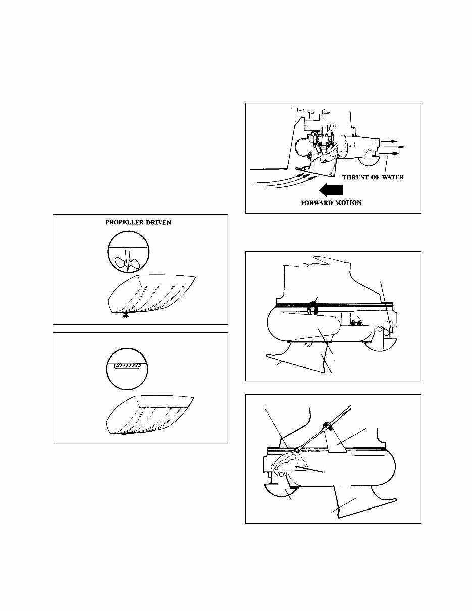
A “fish’s eye view” gives a further comparison
of the difference between a propeller-driven
boat and a jet drive.
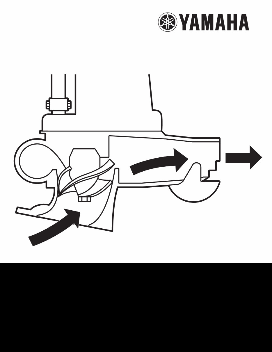
Your Yamaha Jet Drive’s simple design offers
reliable operation with minimal moving parts.
Water is drawn into the unit through the intake
grille by an impeller, driven directly by the
engine drive shaft. The water is then forced at
high pressure through an outlet nozzle that is
directed away from the stern of the boat. This
action creates an opposite force, similar to that
of a jet engine, and drives the boat forward.
When the boat reaches planing speed, the jet
drive discharges water freely into the air and
only the intake grille touches the water. To
obtain reverse, a gate is swung into position
over the outlet, directing the pressure stream in
the opposite direction, thus creating a reverse
thrust to propel the boat backwards.
Conventional controls are used for throttle,
shifting, and steering.
LOCATION OF MAIN COMPONENTS
2
JET DRIVE
JET DRIVE CASING
REVERSE GATE
IMPELLER (INTERNAL)
INTAKE ASSEMBLY
EXHAUST TUBE
GREASE NIPPLE
VENT HOSE
WATER
INTAKE GRILLE
MOTOR ADAPTER PLATE
CAM GATE
CONTROL CABLE
OR ROD
CONTROL CABLE
ANCHOR BRACKET
3
MODEL IDENTIFICATION AND
SERIAL NUMBERS
OUTBOARD IDENTIFICATION
See your Yamaha Outboard Motor Owner’s
Manual for outboard and motor identification
number locations.
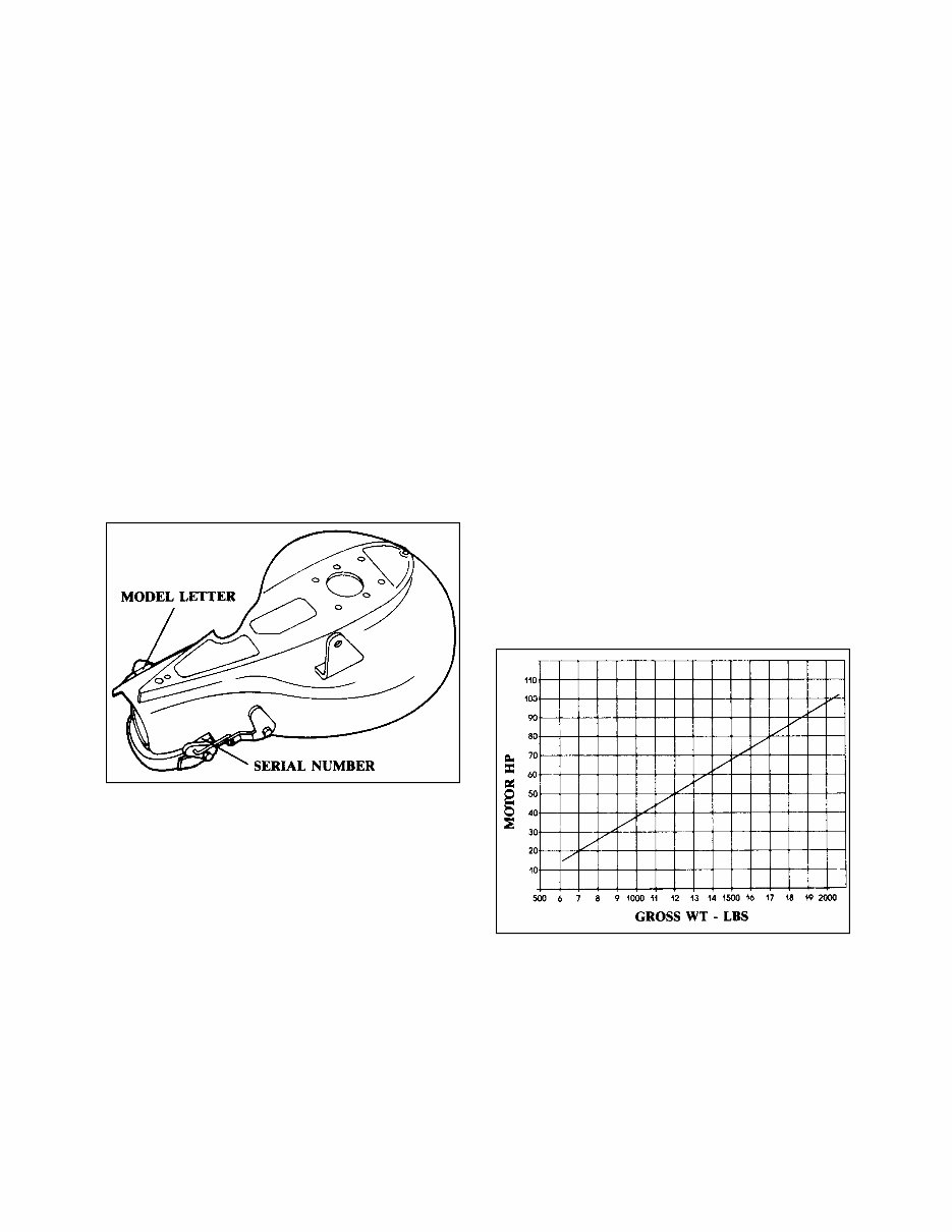
JET DRIVE IDENTIFICATION
The Jet Drive Model Letter is stamped on the
rear, port-side casing. The Jet Drive Serial
Number is stamped on the starboard side of
the casing.
NOTE: The outboard motor and jet-drive unit
model and serial numbers are important when
you need to have service performed or place
an order for parts. For easy reference, please
record these numbers on the inside front cover
of this manual, and also on the inside front cov-
er of your Yamaha Outboard Motor Owner’s
Manual.
APPLICATION AND SIZING
HULL SELECTION
Best performance is obtained by selecting a
light, shallow-draft hull, with a relatively flat (5°
angle, or less), wide bottom. Vee or Multi-Vee
hulls are not recommended (additional drag
would be placed on the Jet Drive’s water intake
housing) because of their greater tendency to
produce cavitation. Aluminum boats are pre-
ferred because of their light weight and dura-
bility. These boats typically have optimum hull
shapes, too.
As a rule, the bottom width for your jet drive
should be at least 48”, and the centerline
length at least 13’.
NOTE: Transom height is especially critical for
jet-driven outboards, which are usually mount-
ed 6” to 7” higher than propeller-driven out-
boards; therefore, it is advisable to use a full
transom with your Jet Drive.
MOTOR SELECTION
MOTOR SIZING
A boat operating at slow speed requires con-
siderably more depth than one that is planing
on the surface of the water. It is important,
therefore, to use sufficient horsepower, and to
not overload your boat beyond its ability to
plane.
The accompanying graph is based on experi-
ence obtained with sled-type boats, using an
outboard-style jet. Gross weights shown
include the motor, hull, fuel, passengers, and
all gear. For a given horsepower, loading
beyond the listed limits will obviously give
reduced performance.
Conversely, slight overpowering, based upon
anticipated load, will result in quicker planing,
reduced throttle settings for a given speed,
and, subsequently, increased efficiency of
operation.
NOTE: The performance output levels of jet-
driven outboards do not reflect true perfor-
mance compared to propeller-driven outboards
of the same powerhead horsepower. The Jet-
Driven model is usually figured to have an out-
put level equal to 70% of the propeller-driven
model. Keep in mind that boat loading, weight,
and hull configuration can significantly affect
the performance of your Jet Drive outboard.
4
ENGINE MOUNTING
MOUNTING HEIGHT
Your Yamaha Jet Drive must be mounted 6” to
7” higher on the transom than propeller-driven
outboards. Therefore, optimum mounting for
15” shafts is on a 20” transom; and for 20”
shafts, a 25” transom.
The positioning of motor height is important
and must be done carefully. One-quarter inch
above the optimum location will allow air to
enter the pump and will result in cavitation and
power loss. Too low a setting will result in
unnecessary drag, water spray, and reduction
in speed.
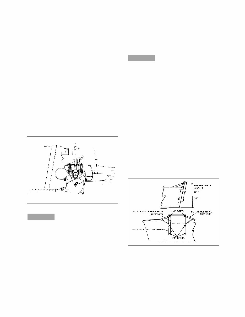
The initial height setting is accomplished by
placing a yardstick or other straightedge
against the boat bottom (not the keel). The top
of the leading edge of the water intake is
adjusted to line up with the top edge of the
straightedge.
TEST RUNNING
When starting your motor for the first time,
make sure water comes out the small hole
at the rear, starboard side of the motor, just
below the powerhead. If no water exits with-
in a short period of time, shut off the motor
and consult your dealer.
After making the initial motor-height setting, it
is time to test-run the boat. If cavitation occurs
(air enters the pump, which causes loss of
thrust and motor overrevving), then you must
lower the engine 1/4” at a time until smooth
operation is obtained.
If smooth operation is obtained with the initial
setting, you should raise the motor in 1/4”
steps until cavitation does occur. Then lower
the motor 1/4”, and mark and lock that location.
This height setting will never need to be
changed, regardless of the load being carried.
Slight cavitation on sharp turns or in rough
water is acceptable, but excessive cavita-
tion is harmful to both motor and pump,
and should be avoided.
The motor tilt pin should be set so the engine
is in a vertical position when the boat is plan-
ing. If the boat rides bow-high, or tends to be
stern heavy, tilt the motor down one step. This
will point the jet stream lower, giving added lift
to the stern.
NOTE: If the tilt angle is changed, then the
motor height must be rechecked.
TRANSOM ELEVATORS
In some applications, an elevated transom may
be required for proper motor height. When
using a bolted-on bracket, set the intake height
1/2” below the bottom of the boat in order to
obtain the widest range of adjustability, as
shown.
1. Glue two pieces of 3/4” exterior plywood
together, using waterproof glue. Clamp or
nail.
2. Bolt to transom at height shown. Use zinc-
plated hardware, with flat washers on both
sides.
CAUTION:
CAUTION:
F40 & F50
MODELS
F80 & F115
MODELS
5
3. Make two diagonal braces from 1/2” elec-
trical conduit. Flatten each end in a vise,
and drill 1/4” holes in them. Determine the
position and angle of the forward bend.
Attach the braces to the boat in a solid
location, such as to the seats or gunwales.
Avoid attachment to flexible aluminum pan-
els.
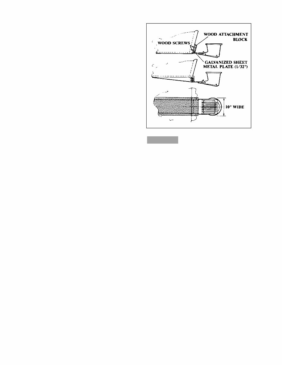
ANTI-CAVITATION PLATES
To reduce spray, or to further reduce cavitation
in rough water, a 1/32”-thick metal plate can be
installed to block the entrance of air into the
water in front of the jet pump’s intake scoop.
Installation of this plate will also allow a slight-
ly higher motor-mounting point (which, of
course, will reduce drag).
The position for proper mounting is shown in
the first part of the accompanying illustration.
An alternate mounting position for the plate
(with the plate attached to a keel or wedge), for
use in “white water,” is shown in the second
and third parts of the illustration. The third part
shows the width of the plate, as well as the
width of the drop-bottom wedge that positions
the intake in more solid water. This installation,
however, reduces shallow-water capabilities
and should be used only when necessary.
After one of these procedures is undertak-
en, the motor height and tilt settings should
be checked, and reset as necessary, to
avoid excessive cavitation that could lead
to impeller damage.
NOTE: Either of the above modifications
should utilize only marine-grade woods; sili-
con-base, waterproofing sealing compounds
(between components and around screws);
and marine-grade paints. Remember, once
you adopt one of these modifications, if
removed or changed, damage may result to
your hull if precautions are not taken to fill
and/or waterproof any holes.
CAUTION:

6
OPERATING INSTRUCTIONS
SHIFTING
The impeller is always engaged and pro-
duces a certain amount of thrust while the
motor is running. “Neutral” is achieved
when the reverse gate is in a middle posi-
tion that balances forward and reverse
thrust. Since the Neutral position on the
shift control may not precisely balance the
thrust, be sure to secure the boat to the
dock or beach the bow of the boat during
cold starts to avoid the possibility of being
thrown off balance as the motor starts.
Except for low-speed maneuvering, do not use
the reverse gate to slow or stop the boat; this
will cause the motor to kick up and out of the
water, similar to hitting a submerged object in a
propeller-driven craft.
REMOTE CONTROL
When using a remote control with a fast-idle
feature, the throttle can be advanced with the
transmission in Neutral for cold engine starts.
When using this fast-idle starting feature, the
shift cam may not immediately engage when
the throttle is returned to the Neutral position
due to water pressure action on the reverse
gate. After the motor has warmed up for 30
seconds or so, stop the motor, move the throt-
tle lever through the shifting mode until the cam
has engaged, place it in Neutral, and restart
the motor. Subsequent warm starts in Neutral
will not require this operation.
STEERING
Experiment with steering your boat in an open
area before attempting downstream river run-
ning. Remember when running downstream,
your speed relative to the shore is the boat’s
speed added to the speed of the river. You may
find quick response to the helm, but due to its
relatively flat-bottomed hull and lack of skeg,
your boat will tend to skid in turns. You must
start your turns early and use sufficient power
to maintain steering control.
If you attempt too tight a turn, at too high a
speed, your boat could spin out, or even
roll over.
Running upstream is easier, as the river speed
is subtracted from the boat’s speed, and the
shore doesn’t go by as fast. You can throttle
back and maneuver your way through tight
areas with good control. At narrow and poten-
tially rough or dangerous passages, you
should stop and study the layout. Look down-
stream so you will recognize it on the return
trip. Once through a bad spot, you may wish to
run down and travel back up the same stretch
to memorize the course you find to be the best.
If you are not sure of a tight area on a down-
stream run, it is better to drift through on the
oars with the motor tipped up, or work the boat
through on a rope.
SHALLOW WATER OPERATION
The life of both impeller and water intake hous-
ing can be greatly increased by avoiding the
intake of sand and gravel. Intake suction, act-
ing on the bottom, will cause your jet drive to
work like a dredge when the intake comes with-
in 2 or 3 inches of the bottom. It is best to shut
off the motor and drift up to the shore when
landing, and to shove off with an oar when
leaving. You can idle through areas less than 1-
foot deep, but there should be more than 1 foot
of water under the boat when opening the
throttle for cruising or planing.
Once planing, boat speed will prevent sucking
in gravel. While great suction exists at the
water intake, your boat passes over the bottom
so quickly that before rocks, sand, and debris
have time to lift, the boat is past the disturbed
area.
While boating in particularly shallow areas,
remember that running on a full plane will make
the boat ride higher in the water. This can allow
you to travel through areas that might be
impossible to traverse at slow speeds. Be sure
you know the type of river bottom before
attempting this, however, in case the boat hits
bottom or runs aground. You should attempt
planing only in areas where the bottom is sand
or gravel. If you hit bottom where there are
large underwater obstacles or sharp rocks, you
may damage the boat and motor.
If you do run aground, shut the motor off imme-
diately and drag the boat to deeper water.
Occasionally, when running aground, a small
rock may lodge between the impeller and
WARNING
WARNING
You're Reading a Preview
What's Included?
Fast Download Speeds
Online & Offline Access
Access PDF Contents & Bookmarks
Full Search Facility
Print one or all pages of your manual
$35.99
Viewed 19 Times Today


Secure transaction
What's Included?
Fast Download Speeds
Online & Offline Access
Access PDF Contents & Bookmarks
Full Search Facility
Print one or all pages of your manual
$35.99
This manual is a comprehensive guide covering Yamaha Jet Drive Operation & Service for Four Stroke EFI Models. It is designed to provide detailed information for both professional mechanics and DIY enthusiasts. The manual encompasses all aspects of the outboard motor, making it an invaluable resource for maintenance and repair.


