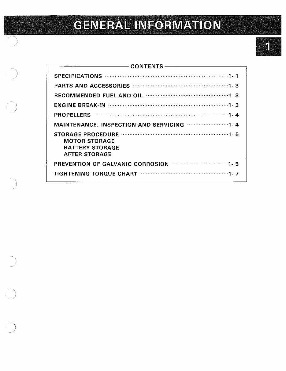
,---------------CONTENTS-------------, SPECIFICATIONS ···········································································1- 1 PARTS AND ACCESSORIES ··························································1- 3 RECOMMENDED FUEL AND OIL ··················································1- 3 ENGINE BREAK-IN ·········································································1- 3 PROPELLERS ··················································································1- 4 MAINTENANCE, INSPECTION AND SERVICING ·························1- 4 STORAGE PROCEDURE ·································································1- 5 MOTOR STORAGE BATTERY STORAGE AFTER STORAGE PREVENTION OF GALVANIC CORROSION ··································1- 5 TIGHTENING TORQUE CHART ·····················································1- 7
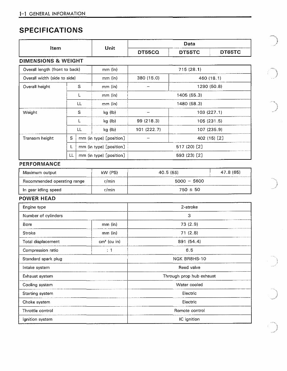
1-1 GENERAL INFORMATION SPECIFICATIONS Data Item Unit DT55CQ DT55TC DT65TC DIMENSIONS & WEIGHT Overall length (front to back) mm (in) 715 (28. 1) Overall width (side to side) mm (in) 380 (15.0) 460(18.1) Overall height s mm (in) - 1290 (50.8) L mm (in) 1405 (55.3) LL mm (in) 1480 (58.3) Weight s kg (lb) - 103 (227 .1) L kg (lb) 99 (218.3) 105 (231.5) LL kg (lb) 101 (222.7) 107 (235.9) Transom height s mm (in type) [position] - 402 (15) [2] L mm (in type) [position] 517 (20) [2] LL mm (in type) [position] 593 (23) [2] PERFORMANCE Maximum output kW (PS) 40.5 (55) I 47.8 (65) Recommended operating range r/min 5000 - 5600 In gear idling speed r/min 750 ±50 POWER HEAD Engine type 2-stroke Number of cylinders 3 Bore mm (in) 73 (2.9) Stroke mm (in) 71 (2.8) Total displacement em' (cu in) 891 (54.4) Compression ratio : 1 6.5 Standard spark plug NGK BR8HS-10 Intake system Reed valve Exhaust system Through prop hub exhaust Cooling system Water cooled Starting system Electric Choke system Electric Throttle control Remote control Ignition system IC ignition
GENERAL INFORMATION 1-2 Data Item Unit DT55CQ DT55TC DT65TC FUEL & OIL Fuel Suzuki recommends that you use alcohol-free unleaded gasoline whenever possible, with a minimum pump octane rating of 85 I"~M method). However, blends of unleaded gasoline and alcohol with equivalent octane content may be used. Fuel to oil mixing ratio Automatic metering Fuel tank capacity L (US/Imp. gal) 25 (6.6/5.5) Engine oil Genuine SUZUKI CCI Oil or NMMA (National Marine Manufacturers Association) certified TC-W3™ oil. Oil tank capacity L (US/Imp. qt) 3.0 (3.2/2.6) Gear oil SUZUKI Outboard Motor Gear Oil (hypoid gear oil SAE #90) Gearcase oil capacity ml (US/Imp. oz) 650 (22.0/22.9) PTT oil Dexron II or an equivalent quality Automatic Transmission Fluid. PTT unit oil capacity ml (US/Imp. oz) 500 (16.9/17.6) BRACKET Trim angle I degree 8- 24 PTT system PTT system ) Number of trim positions 5 PTT system PTT system Maximum tilt angle I degree 75 LOWER UNIT Reversing system Gear Transmission Forward- Neutral- Reverse Reduction system Bevel gear Gear ratio 1. 92 (23/12) Drive line impact protection Spline drive rubber hub Propeller Code number, Blade x Diam. (in) x Pitch (in) S1000, 3x 11-1/2x 10 S 11 QQ, 3 X 11-1 /2 X 11 S1200, 3 X 11-5/8 X 12 S1301, 3 X 11-1/2 X 13 S 1400, 3 X 11-3/8 X 14 S1500, 3x 11-1/4x 15 S1600, 3x 11-1/8x 16 S1700,3x11 X 17 "SS1300, 3 x 11-1/2 x 13 •• SS1400, 3 x 11-3/8 x 14 ** SS: Stainless steel propeller •• SS1600, 3 x 11-1/8 x 16 .. These spec1f1cat1ons are subJect to change Without not1ce.
1-3 GENERAL INFORMATION PARTS AND ACCESSORIES • Genuine Suzuki spare parts and replace- ment items If this outboard motor requires replacement parts or accessories, extreme caution should be exercised when selecting. Suzuki strongly recommends that only genuine Suzuki replacement parts and accessories are used, as poor quality replacement items may create hazardous or unsafe operating conditions. Additionally, it should be noted, that dam- age caused by fitting or using parts other than genuine Suzuki items will not be cov- ered under warranty. RECOMMENDED FUEL AND OIL • Fuel Suzuki highly recommends that alcohol-free unleaded gasoline is used whenever pos- sible, with a minimum pump octane rating R+M of 85 (- 2 - method) or 91 octane (research method). In some areas, only oxygenated fuels are available, but as long as such oxygenated fuels comply with mini- mum octane requirements, they may be used in a Suzuki outboard motor without affecting the terms of the new outboard motor limited warranty. • Engine oil Suzuki also recommend that you use genu- ine Suzuki outboard motor oil. Genuine Suzuki outboard oil has been formulated, tested and approved for this outboard motor. If Suzuki outboard motor oil is not available, be certain that the oil used is high quality 2-cycle outboard oil, marked "NMMA certified TC-W3™." ENGINE BREAK-IN The initial five (5) hours are critically important to ensure correct running of either (A) a brand new motor, or (B) a motor that has been reconditioned or rebuilt. How the motor is operated during this time will have direct bear- ing on its lifespan and long-term durability. • Fuel/oil mixing for break-in period During the first 5 hours of engine operation, a 50 : 1 gasoline/oil mixture must be used in conjunction with the oil injection system. Use only the recommended oil. • Recommended throttle settings The speed ranges listed below are the lower and upper boundaries for each particular break-in period; In all cases, the upper limit must not be exceeded. However, rather than maintain a constant setting, break-in will be enhanced by using varying throttle openings at regular intervals (within the permitted operating range for that specific period). NOTE: After starting the engine, allow sufficient idling time (more than 5 minutes) before opening throttle. 1st hour At least 5 minutes idle speed warm up followed by throttle setting between 1500 RPM and maximum 2500 RPM. Next 2 hours Throttle opening between 3000 RPM and maximum 4000 RPM (1/2 throttle). Final 2 hours Throttle opening between 4500 RPM and maximum 5000 RPM (3/4 throttle). NOTE: During the final hour of break-in, full throttle can be used occasionally, but not continuous- ly and for no more than 30 seconds at a time.
PROPEllERS An outboard motor is designed to develop its rated power within a specified RPM range. In the case of models DT55/DT65, maximum rated power is delivered between 4900 and 5600 RPM. For attaining the specified horsepower, for proper scavenging, optimum fuel economy and maximum engine life, the motor must be equipped with a propeller that permits it to reach rated RPM. The standard propeller will provide satisfactory performance in some applications, preventing engine speeds that are either too high or too low. However, to enable the boat/motor combination to perform correctly for its intended purpose, the correct propeller must be fitted. PROPELLER SELECTION In certain cases, it may be necessary to have a propeller choice with the same boat if the boat is to have different types of usage, such as light loads, then heavy loads, or water-skiing etc. It is best to select a propeller which per- mits the outboard to reach the upper range of the specified RPM band (whilst lightly laden). This ensures that, even when loaded, specified RPM will not fall below "power band". A motor struggling to obtain specified RPM will suffer internal damage caused by overloading and undue stress on components. Similarly, excessively high RPM will adversely affect the motor (although the rev-limiting system prevents this to a certain degree). For propeller selection, please refer to the specifications on page 1-2 for complete list- ing. When selecting a propeller, the only correct way to ascertain engine RPM is to use a ) tachometer, either a dash mount Suzuki acces- sory type or the hand-held digital solar type (Suzuki special tool). Engine tachometer (Digital) Part No.: 09900-26006 GENERAL INFORMATION 1-4 MAINTENANCE, INSPECTION AND SERVICING Keeping the outboard motor in the best oper- able condition at all times involves neither cumbersome measures nor costly expert attention: just carry out simple, ordinary ser- vices in a systematic manner at regular inter- vals. The outboard motor user should be advised to go by the schedule and chart shown in the operator's manual. Before servicing the motor, turn ignition "OFF" and pull emergency switch lanyard. When running the motor in the course of servicing, operate only in well ventilat- ed area. Exhaust emissions are toxic and can be fatal. NOTE: If more than general maintenance is intended, Suzuki recommend the following: (A) Follow Service Manual guidelines thor- oughly., do not take short cuts. (B) Use only Suzuki genuine parts & acces- sories. (C) Use only the approved special tools where required.
1-5 GENERAL INFORMATION STORAGE PROCEDURE MOTOR STORAGE If a customer requests you to prepare the motor for storage (or if the customer wishes to carry out this operation himself), the following procedure should be adhered to: 1 . Remove the motor cover. 2. Thoroughly flush the motor water passages using a flushing attachment. A CAUTION Never operate the motor out of water, even momentarily. Serious engine dam- age may result. 3. While the engine is idling, disconnect the fuel line and immediately spray preserving additive into the carburetor as illustrated until the engine starts to smoke. ~WARNING Keep hands, hair, clothing etc., clear of running motor. 4. When the engine has stopped, turn off the water, and disconnect the flushing attach- ment. 5. Change the gear oil. 6. Lubricate all other specified parts. 7. Apply a coat of automotive wax on the external finish of the motor. If paint damage is evident, apply touch up paint before waxing. 8. Store the motor in an upright position in a dry, well-ventilated area. BATTERY STORAGE 1 . When the outboard motor will not be used for a month or longer, remove the battery and store it in a cool, dark place. 2. If the battery will be stored for a long period of time, check the specific gravity of the fluid at least once a month and recharge the battery when charge level is low. AFTER STORAGE When taking your motor out of storage, follow the procedure below to return it to operating condition: 1. Thoroughly clean the spark plugs. Replace them if necessary. 2. Check the gear-case oil level and if neces- sary, add gear oil. 3. Lubricate all moving parts. 4. Clean the motor and wax the painted sur- faces. 5. Fill the oil tank with recommended engine oil. 6. Bleed air from the oil injection system. A CAUTION If any air is present in the oil injection system, serious engine damage may result. 7. Examine the fuel filter and replace if neces- sary. 8. Fill the fuel tank with 50 : 1 Fuel/oil mix- ture. A CAUTION To ensure adequate lubrication after an extended storage period, a 50 : 1 Fuel/ oil mixture must be used in conjunction with the oil injection system, for 1- 1/2 - 2 hours. 9. Recharge the battery before installing it. PREVENTION OF GALVANIC CORROSION • ZINC PROTECTION BLOCKS To protect against salt water galvanic corro- sion, the motor is equipped with a total of
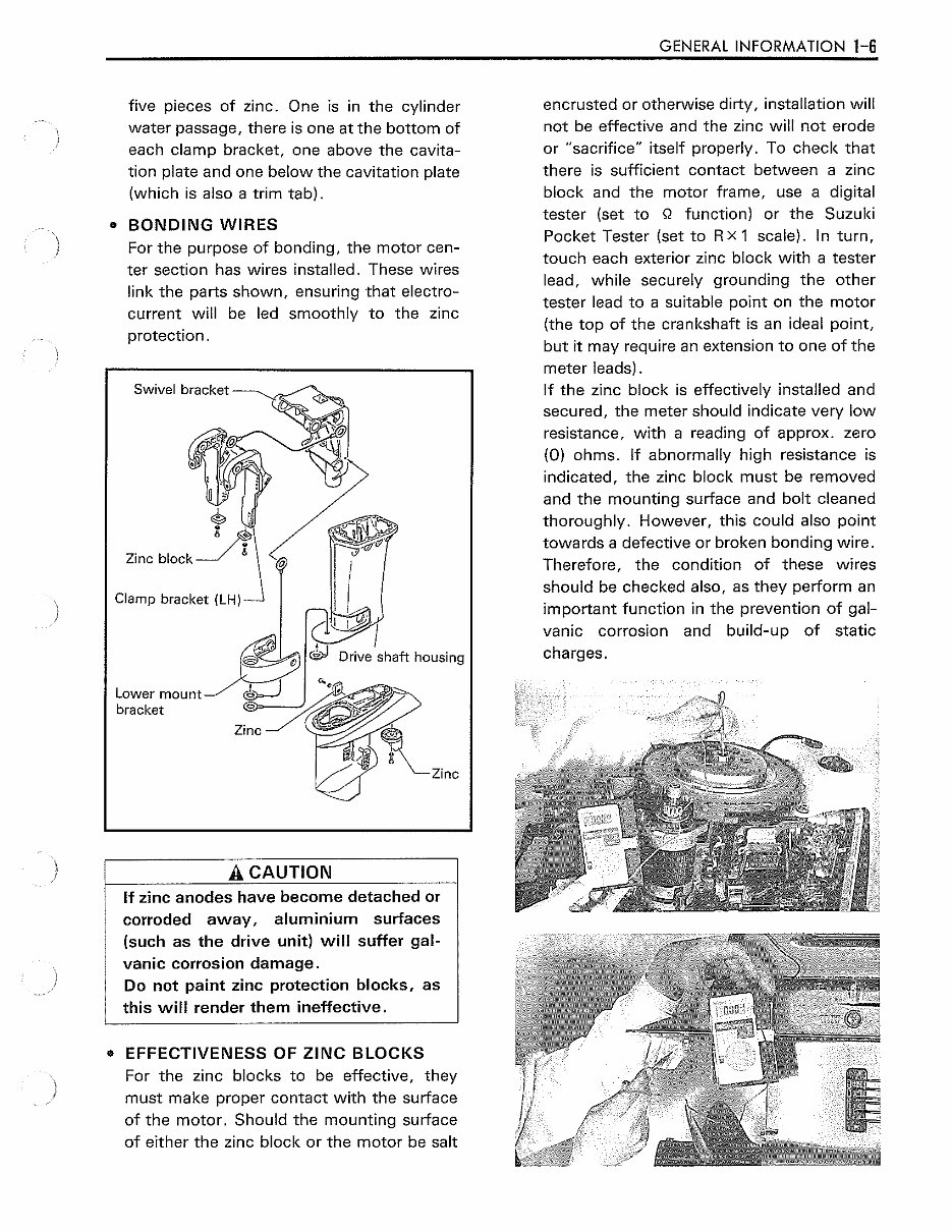
) } five pieces of zinc. One is in the cylinder water passage, there is one at the bottom of each clamp bracket, one above the cavita- tion plate and one below the cavitation plate (which is also a trim tab). • BONDING WIRES For the purpose of bonding, the motor cen- ter section has wires installed. These wires link the parts shown, ensuring that electro- current will be led smoothly to the zinc protection. Clamp bracket (LH) A CAUTION If zinc anodes have become detached or corroded away, aluminium surfaces (such as the drive unit) will suffer gal- vanic corrosion damage. Do not paint zinc protection blocks, as this will render them ineffective, • EFFECTIVENESS OF ZINC BLOCKS For the zinc blocks to be effective, they must make proper contact with the surface of the motor. Should the mounting surface of either the zinc block or the motor be salt GENERAL INFORMATION 1-6 encrusted or otherwise dirty, installation will not be effective and the zinc will not erode or "sacrifice" itself properly. To check that there is sufficient contact between a zinc block and the motor frame, use a digital tester (set to Q function) or the Suzuki Pocket Tester (set to R x 1 scale). In turn, touch each exterior zinc block with a tester lead, while securely grounding the other tester lead to a suitable point on the motor (the top of the crankshaft is an ideal point, but it may require an extension to one of the meter leads). If the zinc block is effectively installed and secured, the meter should indicate very low resistance, with a reading of approx. zero (0) ohms. If abnormally high resistance is indicated, the zinc block must be removed and the mounting surface and bolt cleaned thoroughly. However, this could also point towards a defective or broken bonding wire. Therefore, the condition of these wires should be checked also, as they perform an important function in the prevention of gal- vanic corrosion and build-up of static charges.
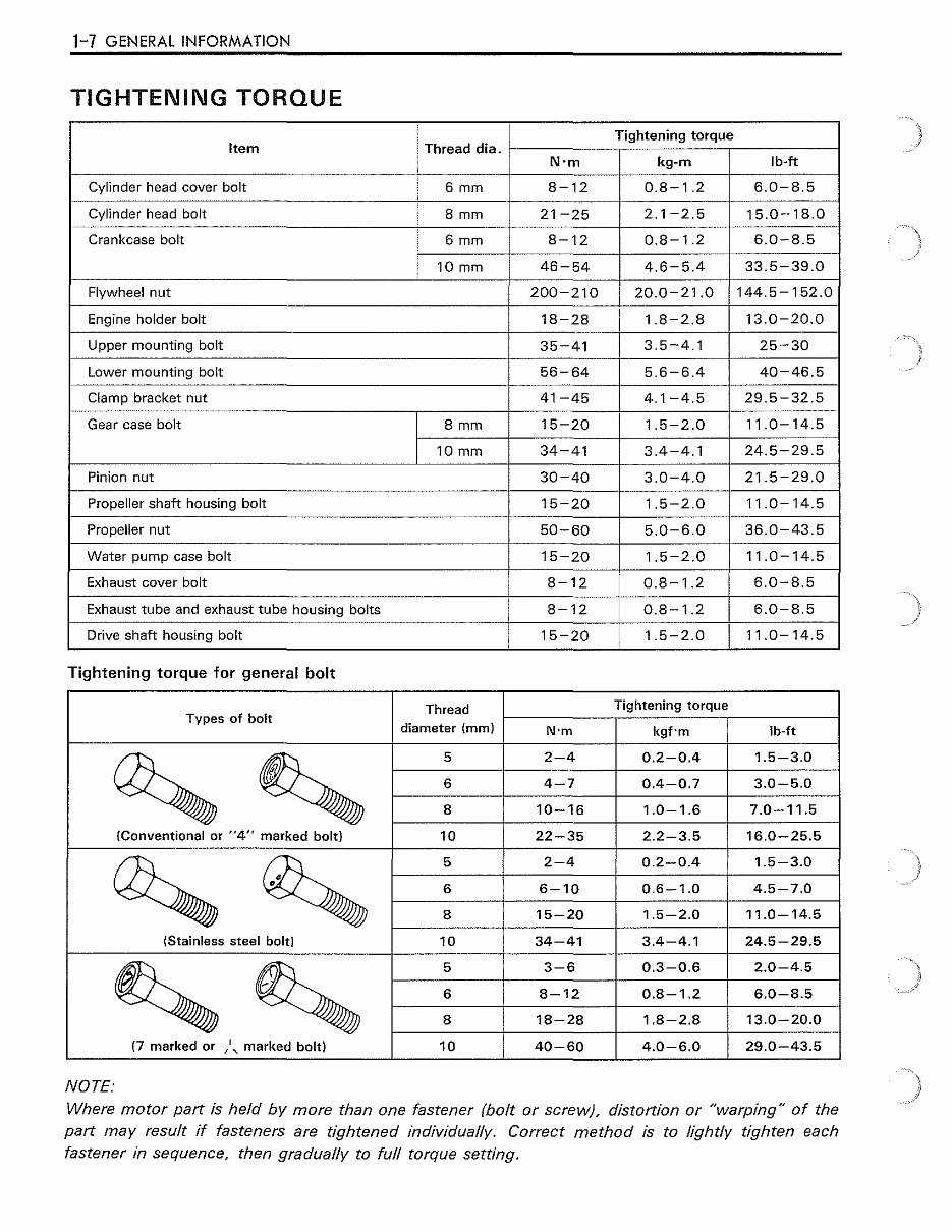
1-7 GENERAL INFORMATION TIGHTENING TORQUE Item Thread dia. Tightening torque N·m kg-m lb-ft Cylinder head cover bolt 6 mm 8-12 0.8 1 .2 6.0-8.5 Cylinder head bolt 8 mm 21-25 2.1-2.5 15.0-18.0 Crankcase bolt 6mm 8-12 0.8-1.2 6.0-8.5 10 mm 46-54 4.6-5.4 33.5-39.0 Flywheel nut 200-210 20.0-21.0 144.5-152.0 Engine holder bolt 18-28 1.8-2.8 13.0-20.0 Upper mounting bolt 35-41 I 3.5-4.1 25-30 Lower mounting bolt 56-64 5.6-6.4 40-46.5 Clamp bracket nut I 41-45 4.1-4.5 29.5-32.5 Gear case bolt 8 mm 15-20 1.5-2.0 11.0-14.5 10 mm 34-41 3.4-4.1 24.5-29.5 Pinion nut 30-40 3.0-4.0 21.5-29.0 Propeller shaft housing bolt 15-20 1.5-2.0 11.0-14.5 Propeller nut 50-60 5.0-6.0 36.0-43.5 Water pump case bolt 15-20 1.5-2.0 11.0-14.5 Exhaust cover bolt 8-12 0.8-1.2 6.0-8.5 Exhaust tube and exhaust tube housing bolts 8-12 0.8-1.2 6.0-8.5 Drive shaft housing bolt 15-20 1.5-2.0 I 11.0-14.5 Tightening torque for general bolt Thread Tightening torque Types of bolt diameter (mm) N·m kgf·m lb·ft ~ ~ 5 2-4 0.2-0.4 1.5-3.0 6 4-7 0.4-0.7 3.0-5.0 8 10-16 1.0-1.6 7.0-11.5 {Conventional or "4" marked bolt) 10 22-35 2.2-3.5 16.0-25.5 ~ ~ 5 2-4 0.2-0.4 1.5-3.0 6 6-10 0.6-1.0 4.5-7.0 8 15-20 1.5-2.0 11.0-14.5 (Stainless steel bolt) 10 34-41 3.4-4.1 24.5-29.5 ~ ~ 5 3-6 0.3-0.6 2.0-4.5 6 8-12 0.8-1.2 6.0-8.5 8 18-28 1.8-2.8 13.0-20.0 (7 marked or , 1 , marked bolt) 10 40-60 4.0-6.0 29.0-43.5 NOTE: Where motor part is held by more than one fastener (bolt or screw). distortion or "warping" of the part may result if fasteners are tightened individually. Correct method is to lightly tighten each fastener in sequence, then gradually to full torque setting.
Thank you for considering this comprehensive Workshop Service Repair Manual for the Suzuki DT55, DT60, and DT65 2-Stroke Outboard Engines manufactured in 1993, 1994, and 1995.
This manual is an invaluable resource for both professional mechanics and DIY enthusiasts, covering every service and repair procedure necessary for maintaining these outboard engines.
With easy-to-follow step-by-step instructions and detailed illustrations, this manual empowers you to save on repair costs by performing maintenance and repairs on your own.
Once downloaded, this manual is yours to keep. You have the flexibility to print specific pages, chapters, or the entire manual. Additionally, you can conveniently access it on your tablet or smartphone.
All models, engines, trim, and transmission types are comprehensively covered in this high-quality Service Repair Workshop Manual, ensuring that every repair and service procedure is detailed from A to Z.
Compatible with all PC and MAC computers, tablets, and mobile phones, this downloadable manual requires only Adobe Reader, which is commonly pre-installed. If not available, Adobe Reader can be easily obtained for free.
Upon payment confirmation via Visa, MasterCard, or PayPal, the manual will be instantly delivered to the email address provided during checkout, ensuring prompt access to the essential repair information.
Rest assured, customer satisfaction is guaranteed with this Workshop Service Repair Manual.