Suzuki DT90 & DT100 OUTBOARD MOTOR SUZUKI DT90 AND DT100 CONDENSED SERVICE DATA NOTE: Metric fasteners nre used throughout outboard motor. TUNE-UP IIp/ rpm : DT90 ... . .. . .... .. .. ... ... .. .. ..... 90/ 5000-5600 DTlOO . . .. ... .. ... .... 100/5000-5600 Bore . ......... .. . . . . ............... 84 mm Stroke (:3.31 in.) ... ....... 64 mm (2.52 in .) .. .. .. ..... ... ... . 4 Number of Cylinders . Displace ment . .. .... 1419 cc (86.6 cu. in.) . .. ... .. . .......... NGK BRSIIS-IO .O.! H.O mm (0.035·0.0:39 in .) . Suzuki Microlink . ... . Mikuni Spark Plug Electrode Gap. Ignition Type Carbureto r Make SIZES-CLEARANCES Piston Ring End Gap: Standard .... Wear Limit Standard Piston Diameter . 0.20-0.40 mm (0.008-0.016 in .) ... .. ............ . 0.80 mm (0.031 in .) . 83.865·8:3.880 mm (3. 3018-:3.:3024 in .) Standard Cylinder Diame ter . ..... .. 84.000-84.015 mm (:3 .:3071-3.3077 in.) Piston·to-Cylinder Clearance: Standard. . . . .. .. ... . ... 0.12 -0.15 mm Wear Limit .. Piston Pin Diameter: Standard W ea r Limit .. Piston Pin Bore Diameter: Standard ..... Wea r Limit ... (0.005-0.006 in .) . .. 0.22 mm (0.0087 in.) . 19.9%-20.000 mm (0.7872-0.7874 in .) .. .. 19.980 mm (0.7866 in.) .. . 20.002·20.010 mm (0. 787,5 -0.7878 in.) ..... . .. 20.030 mm (0.7886 in.) Max. Allowable Crankshaft Runout at Main Bearing . Journal ...... . Max. Allowable Connecting Rod Small End Side Shake . .... 0.05 mm (0.002 in.) . ...... . 5.0 mm (0.20 in.) TIGHTENING TORQUES Cylinder Head Cover: . ... .. ...... ....... 8- 12 N'm Cylinder Head ...... . ... . Cylinders ...... ... .... .. .. .. ..... . (iI-106 in .-Ibs.) .... 28-32 N'm (21-24 ft.-Ibs.) ... 46-54 N'm (34-40 ft.·lbs.) Exhaust Cover .. . Flywhe el Nut ...... ... 8- 12 N'm (71-106 in .- Ibs.) .250-260 N'm (184-192 ft.- lbs.) Gearcase Pinion Nut. . . . . . . . . .. . . . . . .. 80-100 N'm Propeller Shaft Nut (59-7:3 fUbs.) . .50-62 N'm Water Pump Housing ......... .. . . . (37-45 ft.-Ibs.) . 15-20 N'm (11-14 ft.-Ibs.) Standard Screws: Unmarked or Marked " 4" !'imm .... . ...... . ....... 2-4 N'm (18· :35 in .-Ibs.) 6 mm ..... . ...... . .. . .. .. . .. . . . . ... . 4-7N·m (:35-62 in.-Ibs.) ........ 10·16 N'm (88-141 in.-Ibs.) 8111111 ... . ... • ••. 10 mm .... . .. .... ... .. ... .. .. . . . . .. 22-35 N'm (16-25 ft.·lbs.) Stainless Steel 5 mm .. ... . 6 nun . .. 8 mill ..... .. ........... .. .... .. . .2- 4 N'm (18-35 in.-Ibs.) .6 -10 N'm (5:3-88 in .- lbs.) ..... 15-20 N'm (11-14 fUbs.) .... :34 -41 N'm (25-30 ft.-lbs.) 10 mm ........ . Marked "7": 5 mm 6 mm . 8 mill .... 10 mm .. ... . . .. ...... 3-6 N'm (26-5:3 in .-Ibs.) ..... 8-12 N'm (71-106 in .- Ibs.) ... . .. ... 18-20 N'm (13·14 fUbs.) .... .40-60 N'm (29-44 ft .- Ibs.) LUBRICATION The power head is lubri cated by oil mixed with the fu e l. All models are equipped with oil il\jection. The recom- mended oil is Suzuki Outboard Motor Oil or a suitable equivale nt NMMA certified TC-WII engine oil. The recommend ed fuel is unleaded gasoline with a mini- mum pump oclane rating of 85. e nsure adequate engine lubrication. Af· ter break -in period, switch to straight gasoline in the fuel tank . During break-in (first five hours of op- e ration) , a 50; 1 fuel and oil mixture should be used in the fuel tank in com- bination with the oil il\jection system to The lower unit gears and bearings are lubricated by oil contained in the gear- case. The recommended oil is Suzuki Outboard Motor Gear Oil or a good qual-
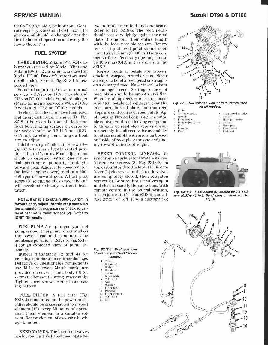
SERVICE MANUAL ity SAE flO hypoid gear lubricalll. Gear- case capacity is ~GO mL (l8.fl fl. oz.). The gearca.-;e oil should be changed after the first to hours of operation and every toO hours thereafter. FUEL SYSTEM CARBURETOR. ~likuni BW:l6-24 car- buretors are used on Model 011)0 and Mikuni \3W40-:32 carburetor.; are us ed on Model DTIOO. Two carburetor.; are us ed on all models. l{efer to Fig. SZ18-1 for ex- ploded view. Standard main jet (12) size for normal service is 111:32.;5 on D1WJ models and #165 on DTlOO nlOdds. Standard pilotjN (6) size for normal service is 1190 on m1l0 models and !i77.5 on m'lOO models. Th check float le\'e1, remo\'e float bowl and invert carburetol: Distance (D- Fig. SZI8-2) between bottom of float: and float bowl mating s urfac e on carbure· tor body should be 9.~-ll.ij mm (0.:37- 0.45 in.). Carefully bend rang on float arm to adj ust. Initial selling of pilot air screw (3- Fig. SZI8-1) from a lightly seated posi- tion is I' ,. to I ". turns. Final adjustment should be pcrfonncd with engine at nor- mal operating tempe rature, running in forward gear. Adjust idle speed switch (on lower engine cover) to obtain 600- 650 rpm in forward gear. Adjust pilot screw (3) so engine idles smoothly and will accelerate cleanly without hesi- tation. NOTE: II unabte to obtain 600·650 rpm in lorward gear, adjust throttle stop screw on top carburetor as necessary or check adjust· ment 01 throttle valve sensor (2). ReIer to IGNITION section. FUEL PUMP, A diaphragm type fu e l pump is usee!. Fuel pump is mounted on the power head and is actuated by crankcase pulsations. I{ef er to Fig. SZI8- 4 for an exploded vi ew of pump as- sembly. Inspect diaphragms (2 and 4) for cracking, detelioration or ot her damage. Defective or questionable co mpon e nts should be renewed. Match marks are provided on cover (I) and body (:1) for correct alignment during reasse mbly. Tighten cover scre ws evenly in a cross- ing patt ern. FUEL FILTER. A fu e l fill e r (Fig. SZI8-4) is mounted on th .. power head. Filter should be di!;&is embled to inspect element (12) every 50 hours of ope ra - tion. Clean clement in a suitable sol- \·enl. Renew eleme nt of excess ive block- age is noted. REED VALVES. The inl et reed valves are located on a V-shaped reed plate be- tween int,lke manifold and cranke-ase. Refer to Fig. SZI8·5. The reed petals should seat very lightly against th e reed plat e throughout their e ntire length with the le,L<;t possihle t ension. Renew reeds if tip of reed peta l stands open more than 0.2 mm (O.OOS in .) from con- ta ct surface. Reed stop opening should be 10.5 mm (0.413 in .) as shown in Fig. SZIS-7. [{ enew re eds if petals are broken, eracked, warp ed, rll sted or be nt. Ne ver attempt to bend a reed petal or straight- en a damaged reed. Never install a bent or damaged reed. Seating s1ll1-ac:e of r eed plate should be smooth and flat. When installing reeds or reed stop, make sure that petals are ce nter ed over the inlet ports in reed plate, anti that reed stops are centered over reed petals. Ap- ply Suzuki Thread Lo ck 1 :342 ora suita- ble eq uival ent thread locking compound to threads of reed stop screws during reassembly. Install reed vain! assemblies i.o intake manifold with alTow embossed on inside of r eed plate (on one end) fac- ing toward outside of engine . SPEED CONTROL LINKAGE. '11> sync hroniz e carburetor throttle valves. loosen two screws (S-Fjg. SZI8-8) on top earburetor throttle lever (L). Rotate lever (L) clockwi se until throttle v<llves are eompletely closed, then retighten screws (S). Be sure throttle valves open and dose at exactly the same time. With remote control in the neutral position, loosen jam nuts (N-Fig. SZIS-9) and ad- just lengt.h of rod (I) so a c:icarance of Fig. SZIS-4-Exploded view of fuel pump and fuel filter as- sembly. I C,I\' l'r :! . 1"}Ij)phm~1Il ;j !\-)dy . 1. U'i iJ ,h F1.Ijl. 1I1 .j SI} l'"i lllol, ,; 11)111''' pbl~' . , " 0" rinj( K. ~\hl1 ~ I W".,ht'r \(I F,hl'r b..",- 11. Pt1ckin" I :! FIJkr .- , I. ·IIwnl I:l. " 0" r loil. If CIII' Suzuki 0190 & 01100 Fig. SZI8-1-Exploded view of carburetors used on all modelS. Hood\' Thr;,n k· \';iln : S('tl .$lI f" :) Pilot ~·rt."., · 1. Inll~t \ '.1\\' 1' 1\: ".' :11 I~in (i . rUt" Jet I. Jo'U;'l1 k 1I 1~~1 ~I)O!.~,1 "!lui .... " !I lif\ '\;. "1 ill :\\111 1\ j"t 1I"ld' ;: r II GiJ..s) WI I i. ) l:dnJl'b I:;. fi n,-u bll wl ,. 1. I.in 'c ro d Fig. SZIS·2-Floal height (D) should be 9.5· I 1.5 mm (0.37-0.45 in.). Bend lang on float arm to ad/usl.
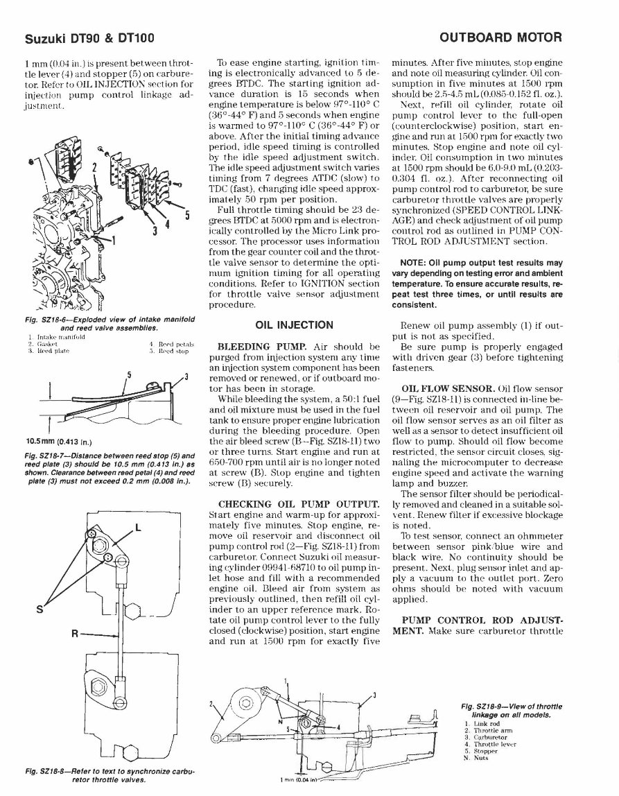
Suzuki DT90 & 01100 I mm (OJH in.) is prese nt between throt- tle lever (.~) and stopper (5) on carbure- tor. Refer 10 OIL IN.JECTION section for iqjeLtion pump control linkage ad- justm ent. Fig. SZI8-6-Exploded view of intake manifold and reed valve Bssemblles. 1 InUtkc rn: inlfold 2. CiiI.S).;.'-l :3 Hced p\au~ 10.5mm (0.413 In.) <1 H('l'd p(-l:, lb :;. H('('d st(Jp Fig. SZI8-7-Dls/Mce belween reed slap (5) and reed plale (3) should be 10.5 mm (0.413 In.) ss shown. CleafsnC6 between reed petal (4) Bnd reed plele (3) musl not exceed 0.2 mm (0.008 In.). R--~ Fig. SZ18-8-Refer to text to synchronize carbu- retor thronle valves. To ease engine stalting, ignition lim- ing is electronically advanced to 5 de- gre es BTDC. The starting ignition ad- van ce duration is 15 seconds when engine temperature is below 87°-1100 C (:36°-44° F) and 5 seconds when enb'ine is warm ed to 97°-110° C (3(j0-44° F) or above. After th e initial timing advance period. idle spe ed timing is controlled by thp. idle speed adju st ment s witch. The idle speed acljustment switch varies timing from 7 degrees ATDC (slow) to TD C (fast), changing idle speed approx- imately 50 rpm per position. Full throttle timing should be 2:3 de- grees BTDC at 5000 rpm and is electron- ically controlled by the Micro Link pro- cessor. The processor uses information from the gear counter co il and the throt- tle valve sensor to det e rmine the opti- mum ignition timing for all operating conditions. Hefer to IGNITION section for throttle ,·alve sensor acljustment procedure. OIL INJECTION BLEEDING PUMP. Air should be purged from ir\jection system any time an irljection system compon en t has been removed or renewed , or if outboard mo- tor has been in s torage. While bleeding the system, a 50:1 fuel and oil mixture must be used in the fuel tank to ensure proper engine lubrication during the bleeding procedure. Open the air bleed screw (B-Fig. SZIH-Il) two or three turns. Start engine and run at MiO-700 rpm until air is no longer not ed at screw (n). Stop engine and tighten screw (il) securely. CHECKING OIL PUMP OUTPUT. Start engine and warm-up for approxi- mately five minutes. Stop engine. re- move oil r ese rvoir and disconnect oil pump control rod (2-Fig. SZIS-Il) from carbureto!: Connect Suzuki oil measur- ing cylinder 08!J4HiH7!O to oil pump in- let hose and fill with a recommen ded engine oiL l3Ieed air from system as previously outlined, then refill oil cyl- inder to an upper re ference mark. Ho- tate oil pump control lever to the fully closed (clockwise) position, start engine and run at 1500 rpm for exactly five 1 mm ro.cw in)';~;:~? OUTBOARD MOTOR minutes. After five minutes. slop engine and note oil mea.,uring cylinder. Oil con- sumption in five minutes at 1500 rpm should be 2.5-4.5 mL (OJ)H5-0.152 fl. oz.). Next. refill oil cylinder, rotate oil pump control lever to the full-open (counterclo ck wise) position, start en- gine and run at 1500 rpm for exactly two minutes. Stop engine and not e oil cyl- imler . Oil consumption in two minutes at 1500 rpm should be (j.O-8.0 mL (0.203- 0.:304 fl. oz.). After reconnecting oil pump co ntrol rod to carburetOl; be sure carburetor throttle valves are properly synchronized (SPEED CONTHOL LiNK- AGE) and chec k acljustment of oil pump control rod as outlined in PUMP CON- TROL ROD ADJUSTMENT sec tion. NOTE: 011 pump output test results may vary depending on testing error and ambient temperature. To ensure accurate results, re- peat test three times, or until results are consistent. Renew o il pump assembly (I) if out- put is not as sp ecified. Be sure pump is properly engaged with driven gear (:3) before tightening fastene rs. OIL FLOW SENSOR. Oililow sensor (9 -Fig. SZIS-II) is co nnected in-line be- tween oil reservoir and oil pump. The oil flow sensor serves as an oil filter as well a.g a sensor to detect insufficient oil flow to pump. Should oil flow become restricted , th e sensor c ir c uit clos es, sig- naling the microcomputer to decrea.,e engine spe ed and activate th e warning lamp and buzzer. The sensor filter should be periodical- ly removed and cleaned in a SUitable sol- vent. He new filter if excessi ve blockage is noted. Tb t es t sensor. conne ct an ohmmeter between sensor pinklblue wire and black wire. No continuity should be present. Next. plug sensor inlet and ap- ply a vacuum to the outl et port. Zero ohms should be noted with vacuum applied. PUMP CONTROL ROD ADJUST- MENT. Make sure carburetor throttle Fig. SZI8-9- VIew ofthrottle linkage on all models. I Link roo 1.. ThTOftl(' ann 3. Cu rhuret.or 4. Thro ttle I('\'~'r 5. S(t)PrK'r S. l\uu
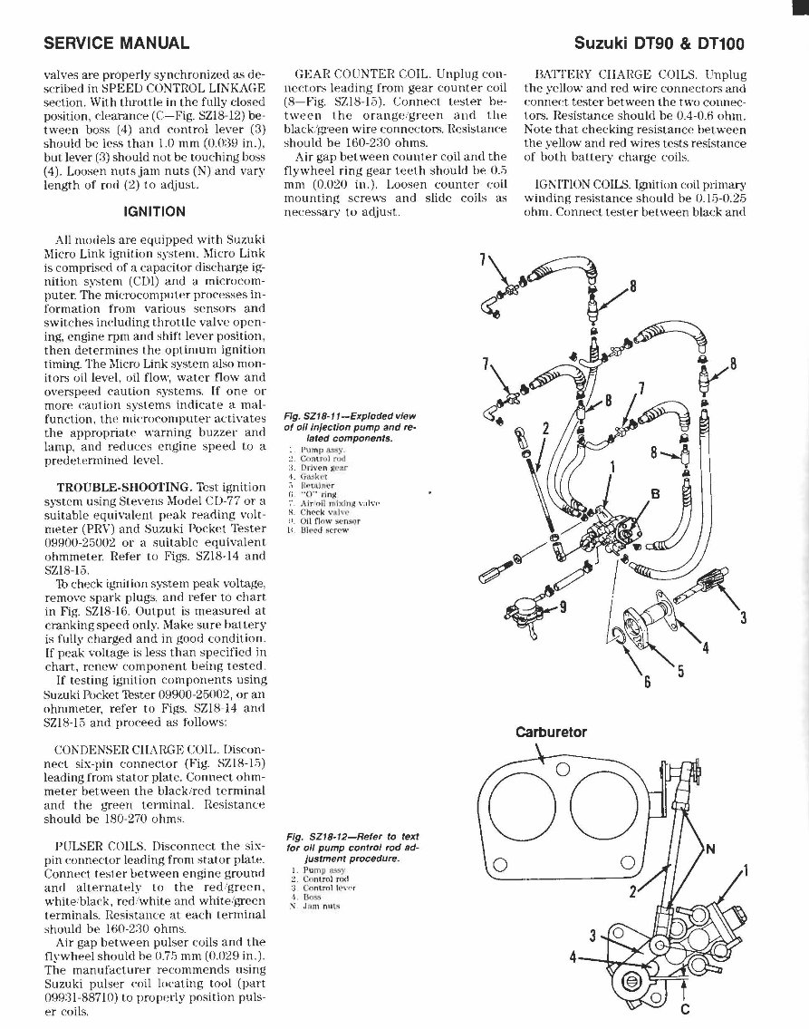
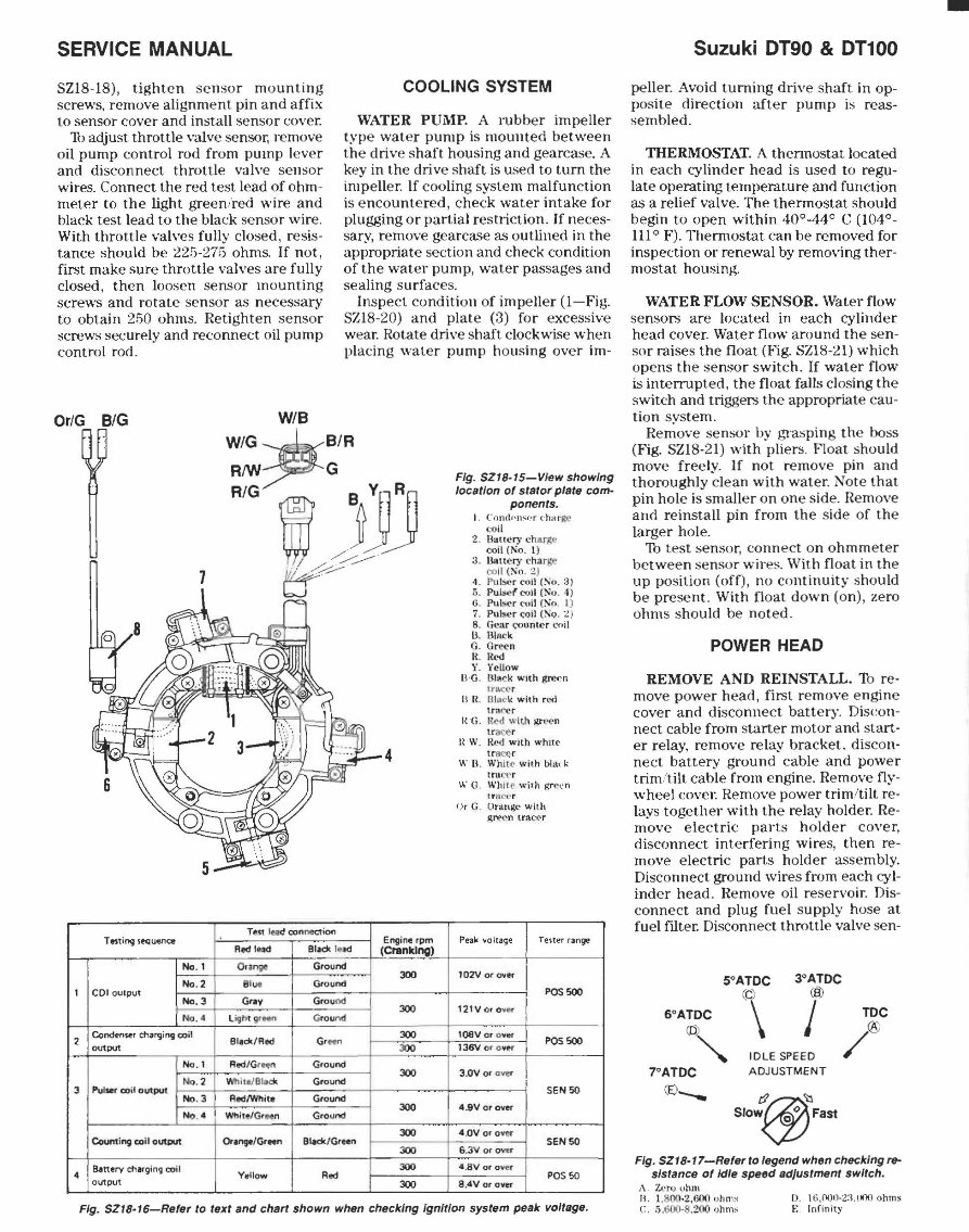
SERVICE MANUAL valves are properly synchronized as de- scribed in SPEED CONTROL LINKAGE section. With throttle in the fully closed position, clearance (C-Fig. SZIS-12) be- tween boss (4) and control lever (3) should be less than 1.0 nlIn (0.0:,9 in.), but lever (3) should not be touching boss (4). Loosen nuts jam nuts (N) and vary length of rod (2) to adjust. IGNITION All models are equipped with Suzuki Micro Link ignition system. 1Ilicro Link is comprised of a capacitor discharge ig- nition system (CDl) and a microcom- puter. The microcomputer processes in- formation from various sensors and switches including throttle valve open- ing, engine rpm and shift lever position, then determines the optimum ignition timing. The ]llicro Link system also mon- itors oil level, oil flow, water flow and overs peed caution systems. If one or more eaution systems indicate a mal- function, the microcomputer activates the appropriate warning buzzer and lamp, and reduees engine speed to a predetermined level. TROUBLE-SHOOTING. Test ignition system using Stevens 1I10dei C D-77 or a suitable equivalent peak reading volt- meter (PRV) and Suzuki Pocket Tester 09900-25002 or a suitable equivalent ohmmeter. Refer to Figs. SZIS-14 and SZIS-L3. 1b check ignition system peak voltage, remove spark plugs, and refer to chart in Fig. SZIS-16. Output is measured at cranking speed only. Make sure battery is fully charged and in good condition. If peak voltage is less than specified in chart, renew component being tested. If testing ignition components using Suzuki Pocket '!ester 09900-25002, or an ohmmeter, refer to Figs. SZIS-14 and SZIS-15 and proceed as follows: COl\DENSER ClIARGE COIL. Discon- nect six-pin connector (Fig. SZIS-15) leading from stator plate. Connect ohm- meter between the black/red terminal and the green terminal. Resistance should be 180-270 ohms. PULSER COILS. Disconnect the six- pin connector leading from stator plate. Connect tester between engine ground and alternately to the red/green, white/black, red/white and white/green terminals. Resistance at each terminal should be 160-230 ohms. Air gap between pulser coils and the flywheel should he 0.7!; mm (0.029 in.). The manufacturer recommends using Suzuki pulser eoil IDeating tool (part 09931-88710) to properly position puls- er coils. GEAR COUNTER COIL. Unplug con- nectors leading from gear counter coil (8-Fig. SZIS-15). Connect tester be- tween the orange/green and the black!green wire eonneetors. Resistance should be 160-230 ohms. Air gap between counter coil and the flywheel ring gear teeth should be 0.5 mm (0.020 in.). Loosen counter coil mounting screws and slide coils as necessary to adjust. Fig. SZI8-11-Exploded vIew of all Injection pump and re- lated components. p\nnp ~~'. (';om rol rod :1. DIi \' (' n " Wa r -1. G~k('l R~'UlITl\~r " 0" ring Air/nil niixlnp; \"~Il\',' H Ch('(:k \' 1.Llv(' o. ()j[ fI( )w s(:nsqr L'I lllt'l'd Ii (; n' ..... Fig. SZI8·12-Refer to text for all pump control rod ad- Justment procedure. Pump i;L'\!iy C.o nlrol rod :3 G<Jn lT I1 1 it.'\'(,'r 1. &$:.1 ~ ,J(, m nuts Suzuki OT90 & OT100 BATTERY CHARGE COILS. Unplug the yellow and red wire connectors and connect tester between the two connec- tors. Resistance should be 0.4-0.6 ohm. Note that checking resistance between the yellow and red wires tests resistance of both battery charge coils. IGNITION COILS. Ignition coil primary winding resistance should be 0.15-0.25 ohm. Connect tester between black and carburetor •
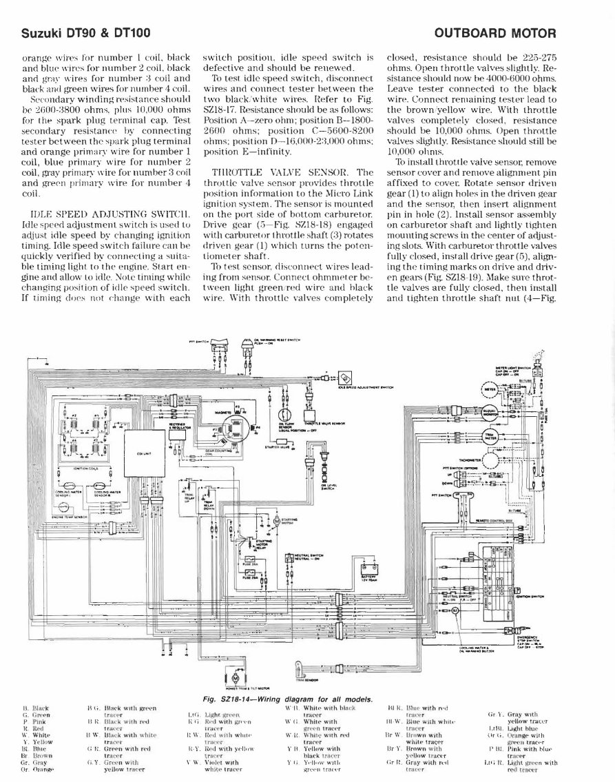
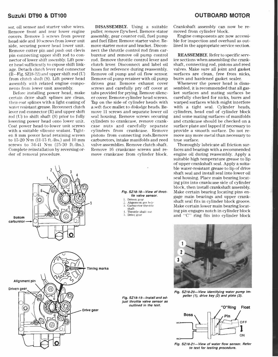
Suzuki DT90 & DT100 orange wires for numb er I co il, black and blue wires for numher 2 co il , black a nd gra)' lI 'ires for numbe r :3 co il and bla('k and !,'Teen wires for number 4 coil . SC'co ndary winding resi stance should br 2fiOO-:3800 ohms. plus 10,000 ohms for I he spark plug term in al cap. T es t seco ndary re sistan('e hy conn ec ting tester betwee n the spark plug terminal and ora nge primary wire for number I coil, blue primary wire for numlJ er 2 coil , gray prinwt>· wire for Ilumbe r 3 coil and gre~1l primary wire for numb er 4 coil. IDLE SPEED ADJUSTING SWITC II. Idle speed adjustment switch is us ed to aC\just idle sp ee d by chanb~ng ignition tim ing. Idle speed switch failure can h., qUickly verified hy conn"cling a suita- ble timing li ght to Ihe ell!,~ne. Slart en- gine and allow to idle. :--.ro te timing while c hanging posi l ion of idl (' speed switc h. If timing dl)('s not d Hl nge with eac h II. UIIl(' j.: B li . Hbu' k \\'nlL j.(n.'{'n G, r.re(·n [run" Lt <" i. p Pln k B I~ 1311t1 .: k wit h n-oJ I~ (i " I"'" ImC(' r W, Whit.· U w. (J IM ).; With "h lu- · I~ W r. Y.:Ilo w ~rnCr'1 Ill. BI'le (; r. Urr·r·n w,Ih n"" I~· Y. Br . UcH .... ·n I nt er-' r Gr. Gray (i . r. Grl~('n w ith " W . Or ()H1 n~' Yl' lIfJ\v I r:It:, 'r switch positioll, idle speed switch is defective and shOU ld be re ll ewed . To t est idl e speed s wite-h , dis co nn ec t wires and co nn ect tes ter het wee n the two bl ac k: whit e wires. Hefer to Fig. SZHl- 17. n.~sistance shou ld be as follows: Position A-zero ohm ; position n-1 800- 2()Ofl ohms; position C-5600-S20 0 ohms: position [) - lU,()OO- 2:l.000 ohms; position E- i nnnity. TlIIIOTTLE VALVI~ SE:--.rSO lt The thrott le valve senso r provides t hrottle position information to the Mi cro Link ig nition system. The sensor is mo unted on the port side of bottom ca rbure tor . Drive gear (5 - Fi g. SZl !l- IS) engaged with carbureto r I hmttl e shaft (:3 ) rotates driven gea r (I) which tllrns the poten- tiometer shaft. lh lest se nsor, disconnect wir es le ad- ing from sensor. Connec t ohmnH't er be- t wee n li ght green /r ed wire and hlack wir e. With I hrotlle \',llves completely Fig. SZI8-14-Wlrlng dIagram for a/l models. \\'"11. Wh il(.' wllh hl:lc~ WAhr j(tC('f\ Ir :l(,\' r }t., 1 with jo/,rpt-n W{i While wllh tr:tN'r Hnoc' n Irllc.'r ( kd ..... lIh Willi" WI( . Whi lt: wu h rl"(1 IrlJ."t"' t tr,H" r' r n r-..; I w ith yd ltl w r II Yl'I lHW with ,rll(:t' r hlllf k It';)Cct V.' JJ\' I w"h ,. f; r,·II"w ..... ,II , whl~ .. " Ir Jl'\'r io(rt'f'11 InlC·l·r OUTBOARD MOTOR closed, resista nce s hould he 225-275 ohms. Open thro ltle valves slightly. Re - sistance should now be 4000-6000 ohms. Lea ve tes ter co nn ec ted to th e black wire. Co nn ect remaining t es ter lead to th e brown ;ye ll ow wir e. With throttle valves (:o mplelely closed, res istance shou ld be 10.000 ohms. Open throttle valves slightl Y. Resi s tan ce should st ill be 10,000 ohms. To installthrotl.le valve senso!; remove se nsor cover and remove alignme nt pin affixed to cove t: Rota te se nsor dri\'en gear (I) to align holes in the driven gear and the sensor , then insert alignment pin in hole (2). Install sensor a,se mbly on carburetor s haft and lightly tight en mounting screws in the ce nter of acljust- ing slots. With ca rburetor throttle valves fully closed, insla ll drive gear (5). align- ing th e timing marks on drive and dliv- en gear;; (Fig. SZ I8-l9 ). Make s ure t hrot- tle valves are fully closed, the n install and tighten throttle shaft nut (4-Fig. --~ IIII'--_~~-' b'~_U BIR , UIII .:' Wi th n'd trul'N (ir "- Comy Wit h III W. B! lIl' ",Hh wh fl " ydlow lran.' r ltu('t' r LlBI. I ... ",hl hlue- Br \\'. Uro wn wilh (l r (i- . tlrt nlt(" with whIr., Ir.tcer SUl ' I''' lracc·r IJr Y. Brnwn w ith I'll!. I'ink with blUt' !H"lIftW , ru.C4:r tt:1Cf~r (;r It (ir.~· ..... ah n·d I.r (; II. Li IUi I ~ n with trP C(' r r('d t rnc~:r
SERVICE MANUAL SZI8-18), tighten sensor mounting screws, remove alignment pin and affix to sensor cover and install sensor cover. 10 adjust throttle valve sensor, remove oil pump control rod from pump lever and disconnect throttle valve sensor wires. Connect the red test lead of ohm- meter to the light green /red wire and black test lead to the black sensor wire. With throttle valves fully closed, resis- tance should be 225-275 ohms. If not, first make sure throttle valves are fully closed, then loosen sensor mounting screws and rotate sensor as necessary to obtain 250 ohms. Retighten sensor screws securely and reconnect oil pump control rod. COOLING SYSTEM WATER PUMP, A rubber impeller type wat er pump is mounted between the drive shart housing and gearcase, A key in the drive shaft. is used to tum the impelle r. If cooling system malfunction is e ncount ered, c heck water intake for plugging or partial r es triction. If neces- sary, remove gearcase as outlined in the appropriate section and check condition of the wat er pump, water passages and sealing surfaces. Inspe ct co ndition of impeller (I-Fig. SZI8-20) a nd plate (3) for excessive wear. Rot.ate drive shaft clockwise when placing wat er pump housing over im- Or/G BIG W/B W/G ~ B/R 1 2 3 4 Rrw? G RIG Wi JJJ ~- 1 4 Test IHd connef;tion Testing sequence Red Iud 911dt le .d Engine rpm (Cranking) No.1 Ounge Ground JOO No .2 81 ue Ground CDloulput No.3 Gfa ... Ground JOO NG.' l ightgr .. n Grou nd Condenwf charging coil BlIck/Red G, _ JOO output JOO No ,1 Red/Gt~n Ground JOO No. 2 Wh lteJBI.ck Ground Pulser util output No .3 Aed/Whj •• Ground I 300 No.' Whitt/a'Mn Ground JOO Counting coil olAPUt Or .... /Gr..", Blick/Green 300 8.ltterv charging coil 300 V.llow Rod output 300 Fig. SZIS·I5-Vlew showing location of slsror plate com- ponents. I. ('oml' < I1..;(' r dmrge (: oil 2. Bath. 'I')' charg<" w il(No. l) :3. llomc ry c: ha tlte coil (~n. 2) -t . Pu~r ("oil (~o. ;3) :). PulsM ('llil (So . 4) .; . 11l1S(' r lvil (Sf). I) I. PulseI'" C;Qil C\Q. 2) 8. (lt.'at (:ounter coil U. Hlack G. Green R. 1<"" Y. Yellow B·G. [3.Il\CK wuh lUCf'rl l'I'a<:N Bit U13d: with n.'tl tmf' er I{ -G. H octi Wi th ~l'('n tr3.;;:er H W. IW(J with whll(- t l(t C(- r \\.' B. Wh it l:' with bl~,("k trac ,-' r \\"0 . Wh lre \\'jlh p;n"('n trllC1~r OrC Or;H\~t' ..... lth e.l"\'('n Lr;\C~'r Peak ,<,o ltage Tester range l02Vof~er POS500 12lVoro .. er I - l08Vor o .. er POS 500 136VQfo ""f 3.0Vor Cvtl' f SEN 50 4.9Vo'~ 4.0V or o V!'r SEN SO S.3V or QYl:r 4.8V Of O Y'll!: r PQS 50 8 .4V or o .. er Fig. SZIS·I6-Refer to text and chert shown when checking Ignition system peak voltage. Suzuki DT90 & DT100 peller. Avoid turning drive shaft in op- posite direction after pump is reas· sembled. THERMOSTAT. A thennostat located in each cylinder head is used to regu· late operating temperature and function as a relief valve. The thermostat should begin to open within 4()0·44° C (104°- 111 ° F). Thermostat can be removed for inspection or renewal by removing ther- mostat housing. WATER FLOW SENSOR. Water flow sensors are located in each cylinder head cover. Water flow around the sen- sor raises the float (Fig. SZ18-21J which opens the sensor switch. If water flow is interrupted, the float falls closing th e switch and triggers the appropriate cau· tion system. Remove sensor by grasping th e boss (Fig. SZI8·21) with pliers. Fl oat should move freely. If not remove pin and thoroughly clean with water. Note that pin hole is smaller on one side. Remove and reinstall pin from the side of the larger hole. To test sensor, connect on ohmmeter between sensor wire,. Wit.h float in the up position (off), no continuity s hould be present. With float down (on), zero ohms should be noted. POWER HEAD REMOVE AND REINSTALL. Th reo move power head, first remove engine cover and disconnect battery. Discon· nect cable from starter motor and start.· er relay, remove relay bracket , discon· nect battery ground cable and power trim/tilt cable from enhrine. Remove fly· wheel cover. Remove power trim/tilt reo lays together with th e relay holder. Re· move electric parts hold er cover, disconnect interfering wires, then reo move electric parts holder assembly. Disconnect ground wires from each cyl· inder head. Remove oil r ese rvoir. Dis· connect and plug fuel supply hose at fuel ftlter. Disconnect throttle valve sen· 5°ATDC (c) 3°ATDC (8) 6°ATDC (0' ~"" \ I IDLE SPEED ADJUSTMENT 7°ATDC (f.) __ ~~ SlOW<f.; Fast TOC /@ Fig. SZIS·17-Refer to legend when checking re- sistance of Idle speed ad/ustmen! switch. A 7..t·r_) ,'hm B. 1. 800-2,600 u tinl" C. :) ,6(10-8, 200 f)hm~ I) . I ll.OOO·2:UOO ol1ms E Infin ity -
Suzuki DT90 & DT100 sor. oil sensor aud startpr valve wir es. Remove front and r ear lower engine cover'S. Remove ;j screws [rom power head side and \0 screws from l owe r unit side, secu ring power Iwad lower unit. Remove cotte r pin and push out clevis pin connecting upper shift rod to con- ne cto r of lower shift il$cmbly. Lift pow- er heafl sufficicntly 10 ex pose s hift link- age . Detach clutch lever rod connector (R - Fig. SZIS-22) and upper s hift rod (U) from clutch shaft (S). Lift power head assembly with related e ngine com po- nent s from lower unit assembly. Before installing power head , make cert.ain drive shaft splines are clean. then coat splines with a light coating of wau'r resistant grease. Reconnect c1uteh lel'er rod connector (R) and upper shift rod (U) to shift shaft (S) prior to flilly lowering power h ead onto lower unit. Coat power head -to-I ower unit screws with a s uitable silicone sea lant. Tight- en 8 mm power h ead retaining screws to 15-20 N'm (11-10 ft.-Ibs.) and 10 mm sc rews to :34-41 N'm (25-:30 ft.-Ibs.). Complete reinstallati on by reversing or- der of removal proced ure. DISASSEMBLY. Using a suitable puller , remove flywheel. Remove stator assembly. gear counter coil. fuel pump and fuel filter. Remove starter valve. Re- move starter motor and bracket. Discon- ne ct the throttle cont rol rod from ca r- buretor and remove o il pu mp co ntrol rod. Remove throttle contro l lever and clutch lever. Disconnect and label oil hos es for reference during reassembly. Remove oil pump and oil flow sensor. Remove oil pump retainer with oil pump driven gear. Remove exhaust cover screws and carefully pry off cove r at tabs provided for prying. Remove silenc- er cove r. Remove cylinder head screws. l'ap on the side of cy linder heads with a soft -face mallet to dislodge heads. Re- move II screws and separate lowe r oil seal housing. Remove screws se('uring cylinders to crankcase, remove c rank- case nuts and carefu lly separate cylinde rs from cra nkcase. Remov e pistons from connecting rods. Remove carburetors, intake manifolds and reed valve assemblies. Remove clutch shaft. Remove 16 crankcase screws and re- move c rankcase from cylinder block. Fig. SZIB-IB-Vlew of throt- tle valve sensor. L Driv'-'Il gear Ah~nm~"t IJIIl lI(. \,· :J. Ctlrbu rc- (nr lhrnU\C :-.hllr, 1. Thrnu\t' ... h:.f1 nUl , J, Dri\'~ gtOJ:l T ~:5~-i- Timing marks Fig. SZIB-19-lnstall and ad· Just throttle vBlve sensor 85 outlined in the text. OUTBOARD MOTOR Crankshaft assembly can now be re - moved from cy linder block . Engine components are now accessi- ble for inspection and overhaul as out- lined in the appropriate service section. REASSEMBLY. Refer to specific serv- ice sections when assembling the crank- shaft, connecting rod, pistons and reed valves. Make sure all joint and gasket surfaces are clean, free fr om nicks, burrs and hard ened gasket sealer. Whenever the power head is disas- sembled, it is recommended that all gas- ket surfaces and mating surfaces be ca refully checked for nicks, burrs and warped surfaces which might int e rfere with a tight seal. Cylinder heads, cylinders, head e nd of cylinder block and some mating surfaces of manifolds and crankcase sho uld be checked on a surfa ce plate and lapped if necessary to provide a smooth surface. Do not re- move any more metal than necessary to true surface. Th oro ughly lubli ea te all friction sur- faces and bearings with a recommended engine oil during reassembly. Apply a suitable high t.emperature grease to lip of upper crankshaft seal. Apply a suita- ble wat.e r-res istant. grease to lip of drive shaft seal and in sta ll seal into lower oil seal housing. Place main bearing locat- ing pins into crankcase side of cylinder block, then install crankshaft assembly. Make ce rtain bearing locating pins en- gage main bealings and upper cra nk- s haft seal fits in cy linder block groove. ;\Iake ce rtain lower main bearing locat- ing pin engages notch in cylinder block and "C " ring fits into cylinder block Fig. SZtB·20-Vlew Identifying water pump 1m· peller (I), drive key (2) and pia Ie (3). Fig. SZI8-21-Vlew of water flow sensor. Refer to text for testing procedure.
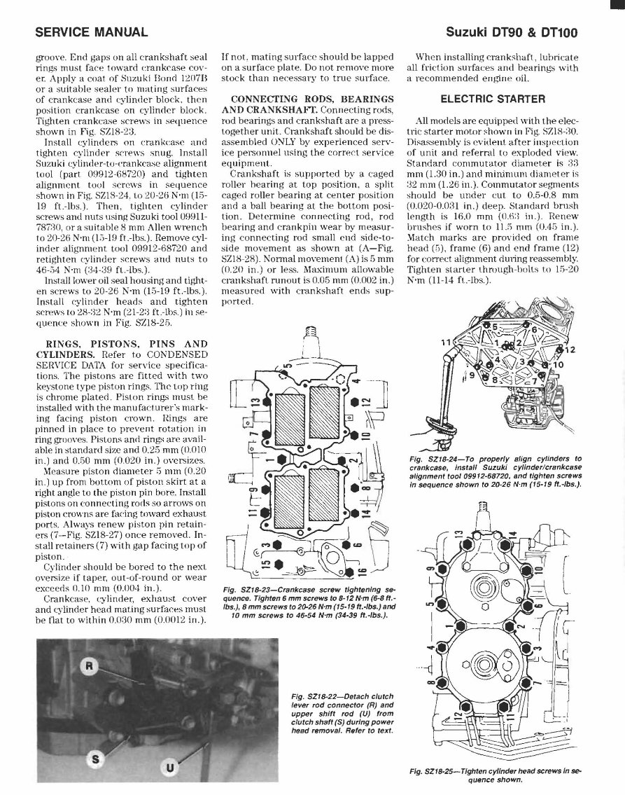
SERVICE MANUAL groove. End gaps on all c rankshaft seal rings must face toward erankc3.-,e cov- er. Apply a coat of Suzuki Bonn IZ07B or a suitahle sea ler to mating surfaces of crank case and cylinde r block. th en position c rank case on cylinner block. Ti ght en cra nk c3.-,e screws in sequenc e shown in Fi g. SZ18- 23. In sta ll cylin de r.; on crankcase and tighten cylinder screws snug. Install Suzuki cylinder-to-cmnkcase alignment tool ( part 099 12-68720) and tight en alignm e nt tool screws in sequenc e s hown in Fig. SZI S-2 4. to 20-26 N'm (Hi- 19 ft.-Ih s.). Then, tighten cylinder screws and nuts ll sing Suzuki tool 09911- 787:10, or a s uit.a bl e S mm Allen wren ch to 20-26 N'm (1 :;- 19 fl.-Ibs.). Remove (-,yl- inder a li gnment tool 09912-687'20 and retighten cylinder screws and nut s to 46-34 N'm (:34-:39 fl. -Ibs.). Insta ll lower o il seal housing and tight- en screws to 20- 26 N'm (15-19 ft.-Ibs.). Insta ll cy li nder he ads and tighten screwS to 28-:32 N'm (21-2:3 ft.-Ibs.) in se- quence shown ill Fig. SZI8-25. RINGS , PISTONS, PINS AND CYLINDERS. Refer to CONDENSED SERVICE DATA for service specifica- tions. The pistons a re fitted with two keyst one type pisto n rings. The top ring is c hrome plated. Pi s lon rings must be installed with th e manu fa ct . urer 's mark- ing facing pi ston c rown . flings are pinned in place to pre vent rotation in ring grooves. Pi stons ann rings are avail- able in slandard size and 0.25 mm (O. OW in .) and 0. 50 mm (0.020 in.) oversizes. I<l eas ure piston diameter 5 mm (0.20 in.) up from bo tt om of piston skirt at a right angle to the piston pin bore. Install pistons on connecting rods so arrows on piston crowns are facing toward exhaust ports . Always renew piston pin retain- ers (7- Fig. SZ I8-27) o nce removed. In- sta ll retain ers (7) with gap facing top of piston. Cy linder should be bo red to the nex t oversize if tape r, o ut -of-round 01' we ar exceeds 0. 10 mm (0.004 in.). Crankcase. cy li nde r, exhaust cover and cy lin de r head mating surfaces must be fl at to within 0.030 mm (0.0012 in.). If n ot, mating su rface s hould be lapp ed on a s ur face pla te . Do not remove more s tock th an n ece ssar y to tru e s urfa ce. CONNECTL-'G RODS, BEARINGS AND CRANKSHAFT. Co nne cting rods, rod bearings and c rankshaft are a press- toge th er unit. Crankshaft should be dis- 3.-<;se mbled ONLY by experienc ed serv- ice personnel using the correct service equipment. Cran ksha ft is supported by a caged ro ll er hea ring at top position, a split caged roller bearing at center position and a ba ll bearing at the bott om posi- tion. Deter mine connecting rod, rod bearing and c rankp in wear by meas ur - ing conn ecting rod small end side -to- side mo\'e me nt as s hown at (A-Fi g. SZIS- 2R). NO lmal movement (A) is 5 mm (0.20 in.) or less. Maximum a ll owable cranksha ft runout is 0.05 mm (0.002 in. ) measu red with c rankshaft end s sup- po rt. e d. Fig. SZI8-23-Crankcase screw tightening Sfl- quence. Tighten 6 mm screws to 8- 12 N'm (6-8 ft .- Ibs.), 8 mm screws to 20-26 N'm (15-19 ft.-Ibs.) and 10 mm screws to 46-54 N'm (34-39 ft.-Ibs.). Fig. SZI8-22-Delach clulch lever rod connector (R) and upper shiff rod (U) 'rom clulch shaft (S) durIng power head removal. Refer to text, Suzuki DT90 & DT100 Wh en installing crank s haft, lu lHi (:a te all frk1.ion s urf a ces and be arings with a r ecomme nded engine oil. ELECTRIC STARTER All mod els are equipped with the elec- tr ic sta rt er motor shown in Fig. SZI 8- :, O. Di sassembly is evident. aft er inspection of unit and referral to exploded view. Sta ndard commutator diamete r is :,:1 mm ( 1. 30 in.) and minimum diamet er is :32 mm (1.26 in.). Commutat.or segme nts should be under cut to 0. 5-0.8 mm (0 .(J20-0.0:1 1 in.) deep. Stan darn b rnsh length is 16.0 mm (O .li:l in .). Re new brush es if worn to 11. 5 mm ((J.4 G in .). :l<l atch ma rks a re provided on f rame h ead (,l), frame (6) and end frame (12) for correct alignment dUling reasse mbly. Ti gh te n s la r ter thro ugh-bolts to [5-20 N'm ( 11 - 14 ft.-lbs. ). Fig. SZI8-24-To properly align cylinders to crankcase, Install Suzuki cylinder/crankcase alignment tool 09912-68720, and tighten screws In sequence shown to 20-26 N·m (15-19 ft.-Ibs.). Fig. SZI8-25- Tighten cylinder head screws In se- quence shown. •
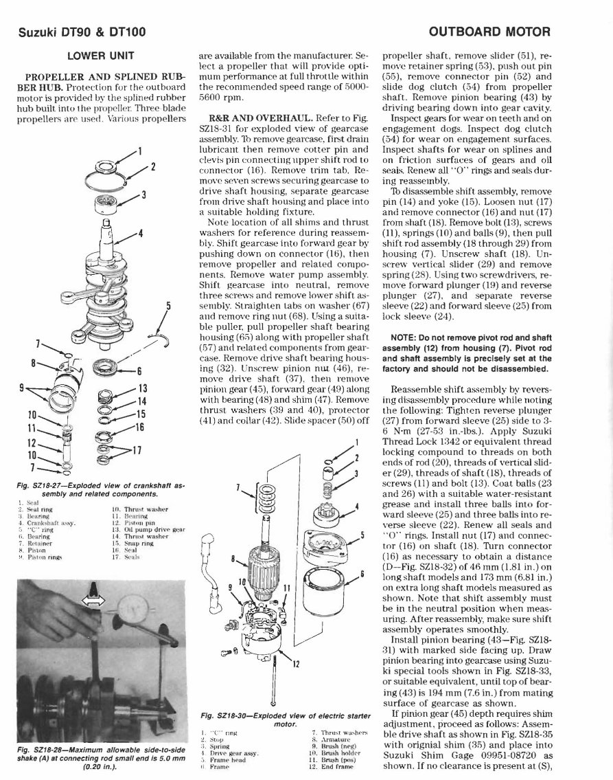
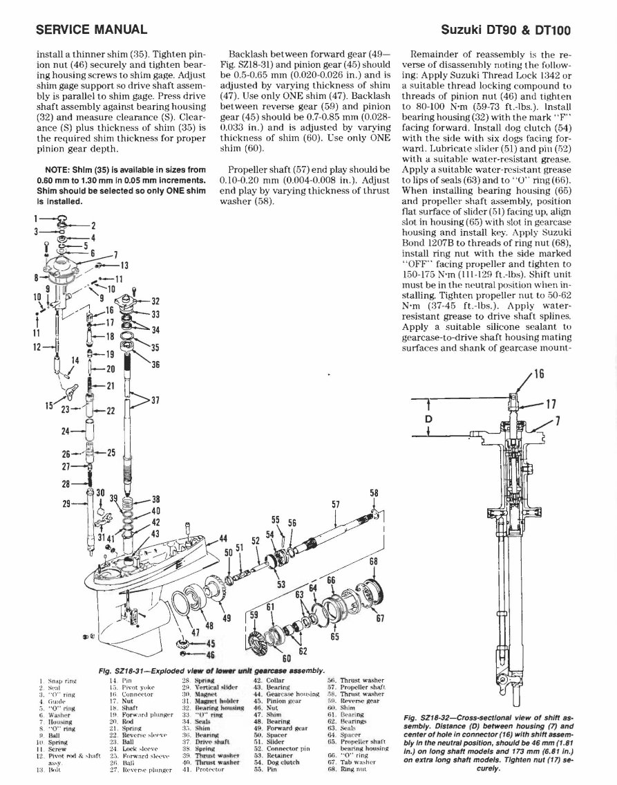
Suzuki DT90 & DT100 LOWER UNIT PROPELLER AND SPLINED RUB- BER HUB. Prot et ti" n for the outboard moto r is provided by the splined rubb er hub built into th e propeller. Three-blade propellers are used . Variolls propellers 5 I 7 ' ;;) ~ ./ 8~« ~ 6 9 "'""~ (("i\ ~ 13 l~ ~14 10~ 0--15 11~ § ~16 12 . ~17 10__ f§r 7_~' Fig. SZI8-27-Exploded view of crsnkshsf1 ss- sembly and relsted components. \. !-;(os l 2. St-al no.: :J . Bc,.rm~ ·i . Crankshaft a." 'y. .J " C" 'r1n,lt Ii . ~~rln!{ 7. I u. ·, ;;al nc· r ~. PIst ... n ~ Pi .. 'tl n nnlt" III, Thm't ..... ;LSh(. ·r II . llt'lIrtn~ I:.!: . PI"IIIII I'ln I :J. 011 pUnllJ drl\'~ lill!l1r 14 . TIlr .... ,' w:l sh"r I :; , Sn •• !) dnlt iii &!II I i' . S!..':d~ Fig. SZI8-28-Maximum allowable slde-Io-slde shake (A) at connecting rod small end Is 5.0 mm (0.20 In.). are available from th e manufacturel: Se- lect a propeller that will provide opt i- mu m performance at full throt lie within the re co mmend ed speed range of 5000- 5600 rpm . R&R AND OVERHAUL, Refer to Fig. SZ18-31 for exp loded view of gear case assembl y. 1b re move geat'case, fir.>t drain lubrica nt then remove cotte r pin and clevis pin eonn ec ting upp er s hift rod to co nnector (16). Remove trim tab, Re- move se\'en screws secUling gea rc:ase to drive shaft housing, sepa r ate gearcase from dlive s haft housing and pl ace int o a s uitable holding fixture . Note location of all shims and thrust wa.<;her,; for reference during r easse m- bly. Shift gearcase int o fo rward gear by pushing down on conn ecto r (16). then remove propeller and rel ated compo- ne nts. Remove water pump assem bl y. Shift gearcase into ne utral , remove th r ee screws and remove lower s hift as- se mbly. ~traighle n tabs on washer (67) and remove ring nut (68). Using a suita- ble puller. pull propeller sha ft bea ring housing (6;;) along with propeller sh aft (57) and relat ed components from gea r- ca.~e. Remove drive sha ft b ea ring hou s- ing (32). Unscr ew pinion nut (46), re- move dlive s haft (37), t hen r emove pinion gear (4 5) . forwa rd gear (49) along with bearing (4S) and shim (47). Remove thrust washers (39 and 40), protecto r (41 ) and collar (42). Slide s pace r (50) off Fig. SZI8-30-Exploded view of eleclrlc starter motor. I ... c .. nn~ :!. ::i t ... ", :.1. S"n nll: I Dr IVe' ~'.':Ir ns~y . .-) ,, ' rAnll' h. ... IJd Ii .. ~mmp 7. Thou!:>1 ...... U- ... hN~ ~, .\rnlltlu. ", ll. UMJ~h (n('g) II). BrUhh hold{' r 11 . Hn !,,,h (PIl1!l) 12. I::nd r nlnle OUTBOARD MOTOR propell er shaft. remove slider (51) , re- move r etain er sp ring (53). push out pin (55), remove co nn ec tor pin (52) and slide dog clut ch (54) from propeller s haft. Remove pinion bearing (43) by driving b eari ng do wn into gear cavity. Inspect gear.> for wear on teeth and on engagement dogs. Ins pect dog clutch (54) for wea r on engageme nt s urfa ces. Inspect shafts for wea r on splin es and on friction s urfac es of gears and oil seals. Renew all "0" rings and sea ls dur- ing reasse mbly. Th disasse mble shift assembly, remove pin (14) and yoke (15). Loosen nut (17 ) and rem ove co nne ctor (16) and nut (17) from shaft (1S). Remove bolt (1:3) , screws (ll), springs (10) and balls (9), then pull shift rod assembly (18 through 29) from ho using (7). Unscrew sha ft (IS). Un- serew vel1ieal slider (29) and remove sp ring (28). Usi ng two screwdrivers. re- move forward plunger (19) a nd reverse plunger (27). and se parat e r everse slee ve (22) and forward sleeve (25) from lock sleeve (24 ). NOTE: Do not remove pivot rod and shalt assembly (12) from housing (7). Pivot rod and shalt assembly Is precisely set at the factory and should not be disassembled. Rea.~semble shift assembly by revers- ing disassembly procedure while n ot ing the following : Tighten revers e plunger (27) from fo rward sleeve (25) side to 3- 6 N'm (27-53 in .-Ibs.). Apply Suzuki Thread Lock 1342 or equivalent t hread loc king compound to thre ads on both ends of rod (20), threads of ve ni cal slid- er (29), threads of shaft (18), threads of sc rews (11) and bolt (13). Coat ba ll s (23 a nd 26) with a s uitable water-r esista nt gr ease and ins tall three ba ll s int o for- ward sleeve (25) a nd three balls int o re- verse sleeve (22). Renew a ll sea ls a nd " 0" rings. Insta ll nut (17) and connec- to r (16) on shaft (IS). Turn co nn ec tor (16) as n ecessa ry to obtain a distance (D- Fig. SZIS-32) of 46 mm (LSI in.) on long shaft mode ls and 173 mm (6.S1 in.) on e xtra long shaft models meas ured as s hown . Note that s hift assembly must be in th e ne utral position wh en mea,- uring. After rea>sembly, make sure shift assem bly ope rat es smoothly. Install pinion bearing (43-Fig. SZlS- 3 1) with ma rk ed side facing up. Draw pinion bearing into geal'case using Suzu- ki special tools s hown in Fig. SZIS-33, or suitable eqUi vale nt , until t op of bear- ing (43) is 194 mm (7.6 in. ) fr om mating s urface of gear case as shown. If pinion gear (45) depth re quires shim ac(justment, proceed as follows: Assem- ble drive s haft as s hown in Fig. SZlS-35 with orignial shim (35) and place into Suzuki Shim Gage 09951-0S720 as shown. If no clearance is prese nt at (S),
SERVICE MANUAL install a thinner shim (35), Tighten pin- ion nut (46) securely and tighten bear- ing housing screws to shim gage, Adjust shim gage support gO drive shaft assem- bly is parallel to shim gage. Press drive shaft assembly against bearing housing (32) and measure clearance (S), Clear- anc e (S) plus thickness of shim (:35) is the required shim thickness for proper pinion gear depth, NOTE: Shim (35) is available in sizes from 0.60 mm to 1,30 mm In 0.05 mm Increments. Shim should be selected so only ONE shim Is Installed, ~J 2 " L5 4 ! c 6 7 / iOJ---13 B-i"!;'-4 ,_~/ ",.-11 lD iJI /-'-;-ID~32 t i /-1 ~:~ J;:33 11 ~ o-lB 34 121 ~-19 ~. 35 Y ~2D 36 1 <::> I \..( ,.-21 IS~3-~ 22 37 24 2S Backlash between forward gear (49- Fig, SZI8-31) and pinion gear (45) should be 0,5-0,65 mm (0,020-0,026 in,) and is adjusted by varying thickness of shim (47). Use only ONE shim (47), Backlash between reverse gear (59) and pinion gear (45) should be 0,7-0.85 mm (0,028- 0,0:33 in,) and is adjusted by varying thickness of shim (60), Use only ONE shim (60), Propeller shaft (57) end play should be 0,10-0,20 mm (0,004-0,008 in,), Adjust end play by varying thickness of thrust washer (58), 58 57 ~ FIg. SZI8-31-EKploded vl_ ot __ geare.se ... embly. L Snap ri n,.: I • . r'jn 1$ svr i •• 42, Collar 5fo. ThrUst \A.' asher 2, Sf.':1 1 1 :1. Ph'ot Yl.k(' 29. V~n.ic.1 Mkh:'r ·1 3. l,k>ari ng 57. Propeller ~hO\(l 3, "0" rin.R Hi C(Jnn~tlOr 30. \I:\gnt.. 't ... . Ge3rcj...$(' hou:-.ing 58, Thru- 'iot wa.~hf!r 4. Cill!(h' 17 . Nut 3 1. N.K'I h(lld~r 45 . PIMion g('ltr '". R('v e rse ~:lr !). "0" rln '" I ", SharT 32. ~~rin(t hou-"in. 1I: 46. Sut f~1. Shim O. WlUhe r 1>1 ,"'o",,'a rJ plLLn~ .. 'r 3:J. "0" ri"J!: 47. Shim 1j1. ikarl ng , lIo1.l~lnM ;In. Rod :3-1. s<-.b 48, lk>lIri nlli 62. 13\ ':lrings 8, "0" r1n~ 2 1. Sprin lZ :) ... ~hiln 49. Fonrr~rd 8'.'ar 63. Seals 11 . 1~1I 22 . Rc~'ersc :-;I.·(·~·(· ;)1). ",' anrlfit 50. Spolccr 64 . Spat(' r 10. Sprin~ 2:). Ball :)7 Orl\'(' ~hllfi. r.t. Slider tIS. PrnV('ller !lhll(( II . Sere ..... 2· 1. Lock ~Ic('\'(' 35 Sprln~ &2. Conn\.'('"lO r pin l)(·:1trin~ hOllsin$[ 12. Pi\'llt ,..-,d &. ... hl1(t 2.). " 'eor' '' ':\fd ~h~~'\' :}9. ThfU)t w;l."h('r 6:). IWUlIn("r 06 . "0" ring :\S. ... y. 21; . Uall ·1(1. n,,'un washer 54 , 00S!: clutch 67 . Tab w:C' hcr );3 . 1~.ll 27 . Ut'~·(,r..c pillng('r ·11. I'ro(N.·(ur 55. Pin 68 . Rin~ nut Suzuki 0190 & 01100 Remainder of reassembly is th e re- verse of disassembly noting th e follow- ing: Apply Suzuki Thread Lock 1342 or a guitable thread locking compound to threads of pinion nut (46) and tighten to 80-100 N-m (59-73 ft.-Ibs.). Install bearing housing (32) with the mark "F" facing forward, Install dog clutch (54) with the side with six dogs facing for- ward, Lubricate slider (51) and pin (52) with a suitable water-resistant grease, Apply a suitable water-resistant grease to lips of seals (63) and to "0" ring ((;6). When installing bearing housing (65) and propeller shaft a"sembly, position nat surface of slider (51) facing up, align slot in housing (65) with slot in gearcase housing and install key. Apply Suzuki Bond 1207B to threads of ring nut (68), install ring nut with the side marked " OFF " facing propeller and tighten to 150-175 N'm (111-129 ft.-Ibs). Shift unit must be in the neutral position when in- stalling, Tighten propeller nut to 50-62 N-m (37-45 ft.-Ibs.). Apply water- resistant grease to drive shaft splines, Apply a suitable silicone sealant to gearcase-to-drive shaft housing mating surfaces and shank of gearcase mount- Fig, SZI8-32-Cross-seCl/onal vIew of shift as- 5emb/y. DISlance (D) between housIng (7) and cenler of hole In conneclor (16) wlrh shift _m- bly In Ihe neulral poslllon, should be 46 mm (1 . 81 In.) on long shaft modals and 173 mm (6.81 In.) on exira long shah models. Tlghlen nul (17) s&- cure/yo
The Suzuki Outboard DT90 DT100 DT115 DT140 DT150 DT150SS DT175 DT200 Service Repair Manual is a comprehensive informational resource suitable for both professional mechanics and DIY enthusiasts. This manual contains easy-to-read text sections accompanied by high-quality diagrams and instructions, making it an invaluable tool for anyone undertaking repair or maintenance tasks.
The manual covers a range of models, including Suzuki DT90, DT100, DT115, DT140 (prior to 1986), DT150, DT150SS, DT175, and DT200. It provides detailed information on various aspects of the outboard, including lubrication, fuel system, oil injection, ignition, cooling system, power head, rings, pistons, pins, cylinders, electric starter, lower unit, and power trim and tilt.
It is available in a file format compatible with all versions of Windows and Mac. The language of the manual is English, and it requires Adobe Reader for access. This manual is a valuable resource for gaining in-depth knowledge about the Suzuki Outboard DT90 DT100 DT115 DT140 DT150 DT150SS DT175 DT200, ultimately saving time and money. Additionally, all pages of the manual are printable, enhancing its usability and convenience.