00 0 1 2 3 4 5 6 7 8 9 10 11 Precautions............................................................... 00-i Precautions ............................................................ 00-1 General Information ................................................... 0-i General Information ............................................... 0A-1 Maintenance and Tune-Up..................................... 0B-1 Power Head................................................................. 1-i Precautions .............................................................. 1-1 Engine General Information and Diagnosis ........... 1A-1 Engine Electrical Devices....................................... 1C-1 Power Unit Mechanical .......................................... 1D-1 Power Unit Lubrication ........................................... 1E-1 Power Unit Cooling System ................................... 1F-1 Fuel System ...........................................................1G-1 Ignition System....................................................... 1H-1 Starting System....................................................... 1I-1 Charging System.................................................... 1K-1 Mid Unit ....................................................................... 2-i Precautions .............................................................. 2-1 Housing and Bracket .............................................. 2A-1 Power Trim and Tilt ................................................ 2B-1 Lower Unit ................................................................... 3-i Precautions .............................................................. 3-1 Right Hand Rotation Unit ....................................... 3A-1 Wire / Hose Routing ................................................... 4-i Precautions .............................................................. 4-1 Wire Routing .......................................................... 4A-1 Fuel / Water Hose Routing ..................................... 4B-1 TABLE OF CONTENTS
Table of Contents 00- i 00 Section 00 CONTENTS Precautions Precautions ............................................... 00-1 Precautions........................................................... 00-1 General Precautions ........................................... 00-1
00-1 Precautions: Precautions Precautions Precautions General Precautions Z9J0110000002 WARNING ! • Proper service and repair procedures are important for the safety of the service mechanic and the safety and reliability of the outboard motor. • To avoid eye injury, always wear protective glasses when filing metals, working on a grinder, or doing other work, which could cause debris. • When two or more persons work together, pay attention to the safety of each other. • When it is necessary to run the outboard motor indoors, make sure that exhaust gas is vented outdoors. • When testing an outboard motor in the water, ensure that the necessary safety equipment is on board. Such equipment includes: flotation aids for each person, fire extinguisher, distress signals, anchor, paddles, bilge pump, first aid kit, emergency starter rope, etc. • When working with toxic or flammable materials, make sure that the area you work in is well ventilated and that you follow all of the material manufacturer’s instructions. • Never use gasoline as a cleaning solvent. • To avoid getting burned, do not touch the engine, engine oil or exhaust system during or shortly after engine operation. • Oil can be hazardous. Children and pets may be harmed from contact with oil. Keep new and used oil away from children and pets. To minimize your exposure to oil, wear a long sleeve shirt and moisture-proof gloves (such as latex gloves) when changing oil. If oil contacts your skin, wash thoroughly with soap and water. Launder any clothing or rags if wet with oil. Recycle or properly dispose of used oil. • After servicing the fuel, lubrication, cooling and/or the exhaust system, check all lines and fittings related to the system for leaks. • Carefully adhere to the battery handling instructions laid out by the battery supplier.
Precautions: 00-2 CAUTION • If parts replacement is necessary, replace the parts with Suzuki Genuine Parts or their equivalent. • When removing parts that are to be reused, keep them arranged in an orderly manner so that they may be reinstalled in the proper order and orientation. • Be sure to use special tools where instructed. • Make sure that all parts used in assembly are clean and also lubricated when specified. • When use of a certain type of lubricant, bond, or sealant is specified, be sure to use the specified type. • When removing the battery, disconnect the negative cable first and then the positive cable. When reconnecting the battery, connect the positive cable first and then the negative cable. • When performing service to electrical parts, if the service procedures do not require using battery power, disconnect the negative cable at the battery. • Tighten cylinder head and case bolts and nuts, beginning with larger diameter and ending with smaller diameter. Always tighten from inside to outside diagonally to the specified tightening torque. • Whenever you remove oil seals, gaskets, packing, O-rings, locking washers, locking nuts, cotter pins, circlips, and certain other parts as specified, always replace them with new. Also, before installing these new parts, be sure to remove any left over material from the mating surfaces. • Never reuse a circlip. When installing a new circlip, take care not to expand the end gap larger than required to slip the circlip over the shaft. After installing a circlip, always ensure that it is completely seated in its groove and securely fitted. • Use a torque wrench to tighten fasteners to the torque values when specified. • Remove grease or oil from screw / bolt threads unless a lubricant is specified. • After assembly, check parts for tightness and operation. • To protect the environment, do not unlawfully dispose of used motor oil, other fluids or batteries. • To protect the Earth's natural resources, properly dispose of used motor parts.
Table of Contents 0- i 0 Section 0 CONTENTS General Information General Information ................................ 0A-1 General Description ............................................. 0A-1 Symbols .............................................................. 0A-1 Abbreviations ...................................................... 0A-1 Wire Color Symbols ............................................ 0A-2 Warning, Caution and Information Label Locations........................................................... 0A-2 Genuine Parts Description .................................. 0A-3 Outboard Motor Identification Number Location ............................................................ 0A-3 Fuel and Oil Recommendations .......................... 0A-3 Break-In Procedures ........................................... 0A-4 Propeller Selection Guide ................................... 0A-4 Battery Requirement ........................................... 0A-5 Powerhead Direction of Rotation Description ..... 0A-5 Specifications ....................................................... 0A-6 Specifications ...................................................... 0A-6 Service Data ....................................................... 0A-8 Tightening Torque Specifications ...................... 0A-13 Special Tools and Equipment ........................... 0A-14 Recommended Service Material ....................... 0A-14 Special Tool ...................................................... 0A-15 Maintenance and Tune-Up ...................... 0B-1 Precautions........................................................... 0B-1 Precautions for Maintenance .............................. 0B-1 General Description ............................................. 0B-1 Recommended Oil and Lubricants ...................... 0B-1 Scheduled Maintenance ...................................... 0B-1 Periodic Maintenance Schedule Chart ................ 0B-1 Lubrication Point ................................................. 0B-2 Service Instructions ............................................. 0B-3 Engine Oil Level Check ....................................... 0B-3 Engine Oil Change and Engine Oil Filter Replacement ..................................................... 0B-3 Gear Oil Change ................................................. 0B-6 Spark Plug Removal and Installation .................. 0B-6 Spark Plug Inspection and Cleaning ................... 0B-7 Tappet Clearance Inspection and Adjustment .... 0B-8 Idle Speed and Idle Air Control (IAC) Duty Inspection ........................................................ 0B-13 Ignition Timing Inspection ................................. 0B-13 Breather Line and Fuel Line Inspection ............ 0B-14 Low Pressure Fuel Filter Inspection .................. 0B-15 High Pressure Fuel Filter Replacement ............ 0B-15 Water Pump and Water Pump Impeller Inspection ........................................................ 0B-16 Propeller / Propeller Nut and Cotter Pin Inspection ........................................................ 0B-16 Anodes Inspection............................................. 0B-17 Bonding Wires Inspection ................................. 0B-18 Battery Inspection ............................................. 0B-18 Bolts and Nuts Inspection ................................. 0B-20 Oil Pressure Check ........................................... 0B-20 Cylinder Compression Pressure Check ............ 0B-21
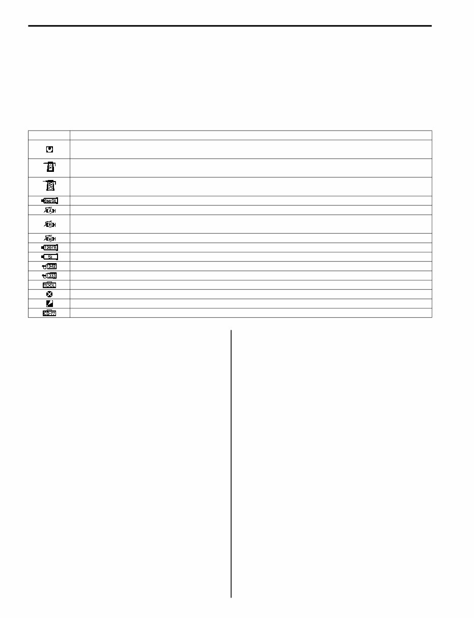
0A-1 General Information: General Information General Information General Description Symbols Z9J0110101001 Listed in the table below are the symbols indicating instructions and other important information necessary for proper servicing. Please note the definition for each symbol. You will find these symbols used throughout this manual. Refer back to this table if you are not sure of any symbol (s) meanings. Abbreviations Z9J0110101002 Abbreviations used in this service manual are as follows: A: ATDC: After Top Dead Center AC: Alternating Current B: BTDC: Before Top Dead Center C: CKP Sensor: Crankshaft Position sensor CMP Sensor: Camshaft Position sensor CTP: Close Throttle Position D: DC: Direct Current DOHC: Double Over Head Camshaft E: ECM: Engine Control Module EX (Ex.): Exhaust F: FP: Fuel Pump G: GND: Ground I: IAC: Idle Air Control IAT: Intake Air Temperature IG: Ignition Ign.: Ignition IN (In.): Intake L: LPS: Lever Position Sensor M: MAP: Manifold Absolute Pressure P: PCV: Positive Crankcase Ventilation PORT: Port PTT: Power Trim and Tilt S: SPS: Shift Position Sensor STBD: Starboard SIGP: Start-In-Gear Protection T: TPS: Throttle Position Sensor Symbol Definition Torque control required. Data beside it indicates specified torque. Apply oil. Use engine oil unless otherwise specified. Apply molybdenum oil solution. (Mixture of engine oil and SUZUKl MOLY PASTE in a ratio of 1 : 1) Apply SUZUKI Outboard Motor Gear Oil. Apply SUZUKI Super Grease A. Apply SUZUKI Moly Paste. 99000-25140 Apply SUZUKI Water Resistant Grease. Apply SUZUKI Bond 1207B. Apply SUZUKI Silicone Seal. Apply SUZUKI Thread Lock 1342. Apply SUZUKI Thread Lock Super 1333B. Use special tool. Do not reuse. Note on reassembly. Use peak voltmeter Stevens CD-77.
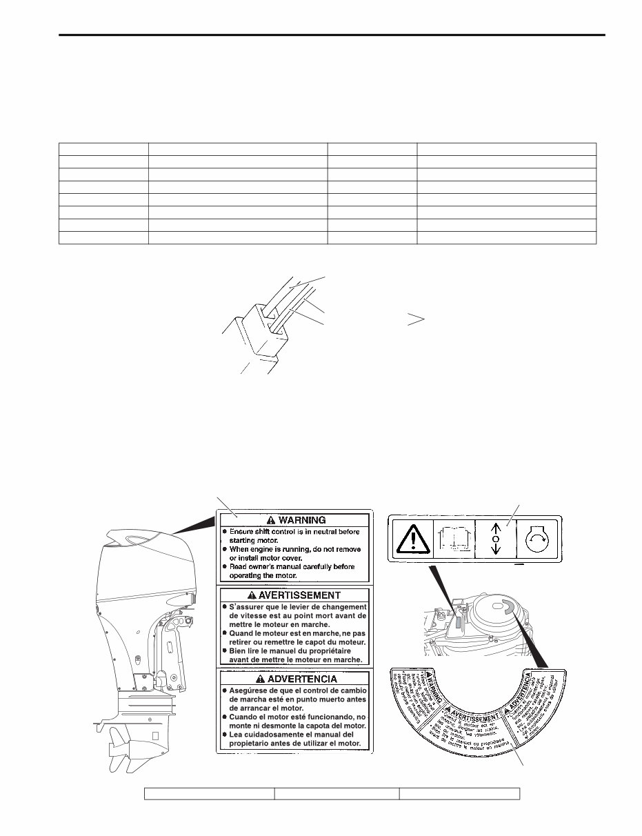
General Information: 0A-2 Wire Color Symbols Z9J0110101010 There are two kinds of colored wire used in this product. One is single colored wire and the other is dual colored (striped) wire. The single colored wire uses only one color symbol. example: B (Black). The dual colored wire uses two color symbols. example: Bl/B. The first symbol represents the base color of the wire and the second symbol represents the color of the stripe. Example: Bl/B (Blue with Black stripe). Warning, Caution and Information Label Locations Z9J0110101011 The figure shows main labels among others that are attached to outboard motor. When servicing outboard motor, refer to WARNING / CAUTION instructions printed on labels. If any WARNING / CAUTION label is found stained or damage, clean or replace it as necessary. Do not reuse a label after it has been removed. Always use new label. Symbol Wire color Symbol Wire color B Black Lg Light green Bl Blue O Orange Br Brown P Pink Dg Dark green R Red G Green V Violet Gr Gray W White Lbl Light blue Y Yellow B (Base Color) Bl (Blue Color) Bl/B Black (Stripe Color) I9J011010001-02 1 3 2 I9J011010004-02 1. Label, engine cover 2. Label, mag cover 3. Label S.I.G.P.
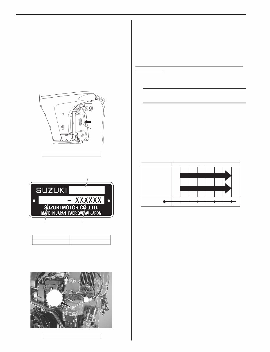
0A-3 General Information: Genuine Parts Description Z9J0110101012 If parts replacement is necessary, Suzuki strongly recommends that you use genuine Suzuki parts or their equivalent. They are precision-made to ensure high quality and correct fit. Outboard Motor Identification Number Location Z9J0110101013 Model, Pre-fix, Serial number The Model, Pre-fix and Serial number of motor are stamped on a plate attached to the clamp bracket. Example Engine Serial Number Location A second engine serial number plate is pressed into a boss on the cylinder block. Fuel and Oil Recommendations Z9J0110101015 Gasoline Suzuki highly recommends that you use alcohol-free unleaded gasoline with a minimum pump octane rating of 87 (R+M/2 method) or 91 (Research method). However, blends of unleaded gasoline and alcohol with equivalent octane content may be used. Allowable maximum blend of a single additive (not combination) 5% Methanol, 10% Ethanol, 15% MTBE CAUTION If leaded gasoline is used, engine damage may result. Use only unleaded gasoline. Engine oil Oil quality is a major contributor to your engine’s performance and life. Always select good quality engine oil. Suzuki recommends the use of a SAE 10 W – 40 NMMA certified oil. If NMMA certified FC-W oil is not available, select a good quality 4-cycle motor oil from the following chart according to the average temperatures in your area. Gear oil Suzuki recommends the use of SUZUKI Outboard Motor Gear Oil. If it is not available, use SAE 90 hypoid gear oil which is rated GL-5 under the API classification system. 1. Identification number plate 1. Model 3. Serial number 2. Pre-fix 1. Serial number plate 1 I9J011010005-01 DF 90 09002F 3 2 1 I9J011010002-03 1 XXXXXX I9J011010012-02 –20 –10 0 10 20 30 –4 14 32 50 68 86 40 104 TEMP. API Classification SAE Viscosity Grade SG SH SL SJ SM 10W–40 10W–30 F C I9J011010003-02
General Information: 0A-4 Break-In Procedures Z9J0110101016 The first 10 hours are critically important to ensure correct running of either a brand new motor or a motor that has been reconditioned or rebuilt. How the motor is operated during this time will have direct bearing on its life span and long-term durability. Break-in period 10 hours Warm-up recommendation Allow sufficient idling time (more than 5 minutes) for the engine to warm up after cold engine starting. Throttle recommendation NOTE Avoid maintaining a constant engine speed for an extended period at any time during the engine break-in period by varying the throttle position occasionally. First 2 hours For the first 15 minutes, operate the engine in-gear at idling speed. During the remaining 1 hour and 45 minutes, operate the engine in-gear at less than 1/2 (half) throttle (3 000 r/min). NOTE The throttle may be briefly opened beyond the recommended setting to plane the boat, but must be reduced to the recommended setting immediately after planning. Next 1 hour Operate the engine in-gear at less than 3/4 (three - quarter) throttle (4 000 r/min). Last 7 hours Operate the engine in-gear at a desired engine speed. However, do not operate continuously at full throttle for more than 5 minutes. Propeller Selection Guide Z9J0110101017 An outboard motor is designed to develop its rated power within a specified engine speed range. The maximum rated power delivered by the DF70 / 80 / 90 models are shown below. Recommended full throttle speed range CAUTION Installing a propeller with pitch either too high or too low will cause incorrect maximum engine speed, which may result in severe damage to the motor. If the standard propeller fails to meet the above requirement, use another pitch propeller to hold the engine speed within the range specified above. Propeller size chart DF70 5 000 – 6 000 r/min DF80 5 000 – 6 000 r/min DF90 5 500 – 6 300 r/min Blade x Dia. (in.) x Pitch (in.) 3 x 14 x 13 3 x 13 and 7/8 x 15 3 x 13 and 3/4 x 17 3 x 13 and 3/4 x 19 3 x 13 and 3/4 x 21 3 x 13 and 3/4 x 23 3 x 13 and 1/2 x 15 3 x 14 x 17 3 x 14 x 19 3 x 14 x 21 3 x 14 x 23
0A-5 General Information: Battery Requirement Z9J0110101018 Suzuki recommends a 12 volt cranking type lead acid battery for the DF70A / 80A / 90A. Minimum battery requirement for starting the engine is provided below. The battery must satisfy one of the specifications described below. NOTE • The specifications listed below are the minimum battery rating requirements for starting the engine. • Additional electrical loads from the boat will require larger capacity batteries. • Dual-purpose (Cranking / Deep Cycle) batteries can be used if they meet the minimum specifications listed below (MCA, CCA, or RC). • Do not use a Deep Cycle battery for the main cranking battery. • The use of Maintenance-Free, sealed, or Gel-Cell batteries is not recommended because they may not be compatible with Suzuki’s charging system. • When connecting batteries in parallel, they must be of the same type, capacity, manufacturer, and of similar age. When replacement is necessary, they should be replaced as a set. • It is recommended that the battery be installed in an enclosed case. • When connecting batteries, hexagon nuts must be used to secure battery leads to battery terminals. Battery Specification 650 Marine Cranking Amps (MCA)/ABYC, or 512 Cold Cranking Amps (CCA)/SAE or 160 Reserve Capacity (RC) Minutes/SAE or 12 V 100 AH Powerhead Direction of Rotation Description Z9J0110101019 This outboard motor is designed with a L.H. (left hand) rotation powerhead utilizing an offset crankshaft. This design has the advantage of reducing the size of the motor and keeping the overall motor’s weight closer to the boat transom and therefore closer to the boat C/G (Center of Gravity). Rotation of the driveshaft is accomplished through a crankshaft drive gear and a driveshaft driven gear. These gears are located beneath the powerhead in the same oil bath location as the camshaft chain. As the rotational direction of the driven gear will be opposite of the drive gear, a left hand rotation powerhead design was adopted to retain a conventional, standard rotation (right hand) propeller shaft output.
The Suzuki DF70A DF80A DF90A 4 Stroke Outboard 2009-2014 Full Service & Repair Manual is a comprehensive factory service repair workshop manual. It is designed for instant access on your computer, tablet, or smartphone without any extra fees or expiry dates.
This professional manual is suitable for both professional mechanics and DIY enthusiasts. It covers all repairs, servicing, and troubleshooting procedures with detailed photos, diagrams, step-by-step instructions, and highly detailed exploded diagrams and pictures to ensure every job is completed correctly.
Users have the flexibility to print out a single page or the entire manual as per their requirement. Additionally, the manual can be used on multiple computers without any limitations or trial periods, and it does not expire or require renewal fees. It is fully compatible with Windows and MAC computers.
For a reliable and detailed resource for servicing and repairing Suzuki DF70A, DF80A, and DF90A 4-stroke outboard engines, this manual is an invaluable asset.