

2006-2013 Suzuki DF25 (25HP) V2 4-Stroke Outboard Service & Repair Manual
What's Included?
Fast Download Speeds
Online & Offline Access
Access PDF Contents & Bookmarks
Full Search Facility
Print one or all pages of your manual

GROUP INDEX
GENERAL INFORMATION
1
PERIODIC MAINTENANCE
2
ENGINE CONTROL SYSTEM
3
ENGINE ELECTRICAL
4
FUEL SYSTEM
5
RECOIL STARTER
6
POWER UNIT
7
MID UNIT
8
LOWER UNIT
9
WIRE/HOSE ROUTING
10
12
© COPYRIGHT SUZUKI MOTOR CORPORATION 2006
FOREWORD
This manual contains an introductory description of
the SUZUKI DF25 Outboard motor and procedures
for inspection, service and overhaul of their main
components.
General knowledge information is not included.
Please read the GENERAL INFORMATION section
to familiarize yourself with basic information con-
cerning this motor. Read and refer to the other
sections in this manual for information regarding
proper inspection and service procedures.
This manual will help you better understand these
outboard motors, assisting you in providing your
customers with optimum and quick service.
!
NOTE:
This manual is compiled based on 2006 (K6) model.
• This manual has been prepared using the
latest information available at the time of
publication.
Differences may exist between the content of
this manual and the actual outboard motor.
• Illustrations in this manual are used to show
the basic principles of operation and work
procedures and may not represent the actual
outboard motor in exact detail.
• This manual is intended for use by techni-
cians who already possess the basic knowl-
edge and skills to service SUZUKI outboard
motors.
Persons without such knowledge and skills
should not attempt to service SUZUKI out-
board engines by relying on this manual only
and should contact an authorized SUZUKI
outboard motor dealer.
Apprentice mechanics or do-it-yourself
mechanics that don’t have the proper tools
and equipment may not be able to properly
perform the services described in this man-
ual.
Improper repair may result in injury to the
mechanic and may render the engine unsafe
for the boat operator and passengers.
HOW TO USE THIS MANUAL
TO LOCATE WHAT YOU ARE LOOKING FOR:
1. The text of this manual is divided into sections.
2. The section titles are listed on the previous page in a
GROUP INDEX. Select the section needed for reference.
3. Holding the manual as shown at the right will allow you to
find the first page of the section easily.
4. The first page of each section contains a table of contents to
easily locate the item and page you need.
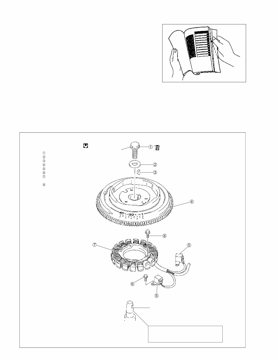
COMPONENT PARTS AND IMPORTANT ITEM ILLUSTRATIONS
Under the name of each system or unit, an exploded view is provided with work instructions and other ser-
vice information such as the tightening torque, lubrication and locking agent points.
Example:
Flywheel bolt
Washer
Key
Flywheel
CKP sensor
Screw
Battery charge &
Power source coil
Bolt
196 N
.
m
(19.6 kg-m, 142 lb-ft)
Crankshaft
NOTE:
Clean flywheel and crankshaft mating
surfaces with cleaning solvent.
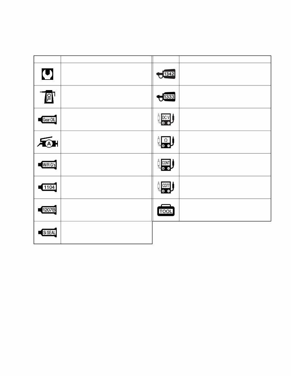
SYMBOL
Listed in the table below are the symbols indicating instructions and other important information necessary
for proper servicing. Please note the definition for each symbol. You will find these symbols used throughout
this manual. Refer back to this table if you are not sure of any symbol(s) meanings.
SYMBOL DEFINITION SYMBOL DEFINITION
Torque control required.
Data beside it indicates specified
torque.
Apply THREAD LOCK “1342”.
Apply oil. Use the engine oil unless oth-
erwise specified.
Apply THREAD LOCK SUPER “1333B”.
Apply SUZUKI OUTBOARD MOTOR
GEAR OIL.
Measure in DC voltage range.
Apply SUZUKI SUPER GREASE “A”. Measure in resistance range.
Apply SUZUKI WATER RESISTANT
GREASE.
Measure in continuity test range.
Apply SUZUKI BOND “1104”. Use peak voltmeter “Stevens CD-77”.
Apply SUZUKI BOND “1207B”. Use special tool.
Apply SUZUKI SILICONE SEAL.

ABBREVIATIONS
Abbreviations used in this service manual are as follows:
BTDC : Before Top Dead Center
DC : Direct Current
EX (Ex.) : Exhaust
IN (In.) : Intake
PORT : Port
STBD : Starboard
PTC : Positive Temperature Coefficient Thermistor

1
GENERAL INFORMATION 1-1
CONTENTS
GENERAL INFORMATION
WARNING/CAUTION/NOTE .........................................................................1- 2
GENERAL PRECAUTIONS ...........................................................................1- 2
IDENTIFICATION NUMBER LOCATION ......................................................1- 4
FUEL AND OIL ..............................................................................................1- 5
GASOLINE RECOMMENDATION .........................................................1- 5
ENGINE OIL ...........................................................................................1- 5
ENGINE BREAK-IN .......................................................................................1- 6
WARM-UP RECOMMENDATION ..........................................................1- 6
THROTTLE RECOMMENDATION .........................................................1- 6
PROPELLERS ...............................................................................................1- 7
CYLINDER NUMBER ....................................................................................1- 7
SPECIFICATIONS .........................................................................................1- 8
SERVICE DATA .............................................................................................1-10
TIGHTENING TORQUE .................................................................................1-16
SPECIAL TOOLS ..........................................................................................1-18
MATERIALS REQUIRED ..............................................................................1-21

1-2 GENERAL INFORMATION
WARNING/CAUTION/NOTE
Please read this manual and follow its instructions carefully. To emphasize special information, the symbol
and the words WARNING, CAUTION and NOTE have special meanings. Pay special attention to the mes-
sages highlighted by these signal words.
!
Indicates a potential hazard that could result in death or injury.
"
Indicates a potential hazard that could result in motor damage.
NOTE:
Indicates special information to make maintenance easier or instructions clearer.
Please note, however, that the warnings and cautions contained in this manual cannot possibly cover all
potential hazards relating to the servicing, or lack of servicing, of the outboard motor. In addition to the
WARNING and CAUTION stated, you must also use good judgement and observe basic mechanical safety
principles.
GENERAL PRECAUTIONS
!
• Proper service and repair procedures are important for the safety of the service mechanic
and the safety and reliability of the outboard motor.
• To avoid eye injury, always wear protective goggles when filing metals, working on a grinder,
or doing other work, which could cause flying material particles.
• When two or more persons work together, pay attention to the safety of each other.
• When it is necessary to run the outboard motor indoors, make sure that exhaust gas is vented
outdoors.
• When testing an outboard motor in the water and on a boat, ensure that the necessary safety
equipment is on board. Such equipment includes: flotation aids for each person, fire extin-
guisher, distress signals, anchor, paddles, bilge pump, first-aid kit, emergency starter rope,
etc.
• When working with toxic or flammable materials, make sure that the area you work in is well-
ventilated and that you follow all of the material manufacturer’s instructions.
• Never use gasoline as a cleaning solvent.
• To avoid getting burned, do not touch the engine, engine oil or exhaust system during or
shortly after engine operation.
• Oil can be hazardous. Children and pets may be harmed from contact with oil. Keep new and
used oil away from children and pets. To minimize your exposure to oil, wear a long sleeve
shirt and moisture-proof gloves (such as dishwashing gloves) when changing oil. If oil con-
tacts your skin, wash thoroughly with soap and water. Launder any clothing or rags if wet
with oil. Recycle or properly dispose of used oil.
• After servicing fuel, oil/engine cooling system and exhaust system, check all lines and fit-
tings related to the system for leaks.
• Carefully adhere to the battery handling instructions laid out by the battery supplier.

GENERAL INFORMATION 1-3
"
• If parts replacement is necessary, replace the parts with Suzuki Genuine Parts or their equiv-
alent.
• When removing parts that are to be reused, keep them arranged in an orderly manner so that
they may be reinstalled in the proper order and orientation.
• Be sure to use special tools when instructed.
• Make sure that all parts used in assembly are clean and also lubricated when specified.
• When use of a certain type of lubricant, bond or sealant is specified, be sure to use the speci-
fied type.
• When removing the battery, disconnect the negative cable first and then the positive cable.
When reconnecting the battery, connect the positive cable first and then the negative cable.
• When performing service to electrical parts, if the service procedures do not require using
battery power, disconnect the negative cable at the battery.
• Tighten cylinder head and case bolts and nuts, beginning with larger diameter and ending
with smaller diameter. Always tighten from inside to outside diagonally to the specified tight-
ening torque.
• Whenever you remove oil seals, gaskets, packing, O-rings, locking washers, locking nuts,
cotter pins, circlips, and certain other parts as specified, always replace them with new. Also,
before installing these new parts, be sure to remove any left over material from the mating
surfaces.
• Never reuse a circlip. When installing a new circlip, take care not to expand the end gap larger
than required to slip the circlip over the shaft. After installing a circlip, always ensure that it is
completely seated in its groove and securely fitted.
• Use a torque wrench to tighten fasteners to the torque values when specified.
• Remove grease or oil from screw/bolt threads unless a lubricant is specified.
• After assembly, check parts for tightness and operation.
• To protect the environment, do not unlawfully dispose of used motor oil, other fluids and bat-
teries.
• To protect the Earth’s natural resources, properly dispose of used motor parts.
1-4 GENERAL INFORMATION
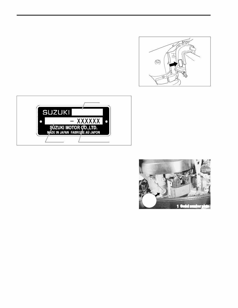
IDENTIFICATION NUMBER LOCATION
MODEL, PRE-FIX, SERIAL NUMBER
The MODEL, PRE-FIX and SERIAL NUMBER of motor are
stamped on a plate attached to the clamp bracket.
Example
ENGINE SERIAL NUMBER
A second engine serial number plate is pressed into a boss on
the cylinder block.
MODEL
PRE-FIX SERIAL NUMBER
DF 25
02502F
1. Serial number plate
1 1
XXXXXX
GENERAL INFORMATION 1-5
FUEL AND OIL
GASOLINE RECOMMENDATION
Suzuki highly recommends that you use alcohol-free unleaded
gasoline with a minimum pump octane rating of 87 (R/2+M/2
method) or 91 (Research method). However, blends of
unleaded gasoline and alcohol with equivalent octane content
may be used.
Allowable maximum blend of a single additive (not combination):
5% Methanol, 10% Ethanol, 15% MTBE
"
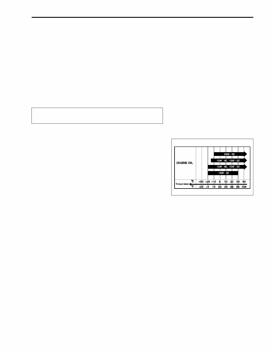
ENGINE OIL
Use only oils that are rated SE, SF, SG, SH or SJ under the API
(American Petroleum Institute) classification system or NMMA
FC-W classification system.
The viscosity rating should be SAE (or NMMA FC-W) 10W-40.
If SAE (or NMMA FC-W) 10W-40 motor oil is not available,
select an alternative according to the chart at right.
If leaded gasoline is used, engine damage may result.
Use only unleaded gasoline.

1-6 GENERAL INFORMATION
ENGINE BREAK-IN
The first 10 hours are critically important to ensure correct run-
ning of either a brand new motor or a motor that has been recon-
ditioned or rebuilt. How the motor is operated during this time
will have direct bearing on its life span and long-term durability.
Break-in period: 10 hours
WARM-UP RECOMMENDATION
Allow sufficient idling time (more than 5 minutes) for the engine
to warm up after cold engine starting.
THROTTLE RECOMMENDATION
NOTE:
Avoid maintaining a constant engine speed for an extended
period at any time during the engine break-in by varying the
throttle position occasionally.
1. FIRST 2 HOURS
For first 15 minutes, operate the engine in-gear at idling
speed.
During the remaining 1 hour and 45 minutes, operate the
engine in-gear at less than 1/2 (half) throttle (3 000 r/min).
NOTE:
The throttle may be briefly opened beyond the recommended
setting to plane the boat, but must be reduced to the recom-
mended setting immediately after planing.
2. NEXT 1 HOUR
Operate the engine in-gear at less than 3/4 (three-quarter)
throttle (4 000 r/min).
3. LAST 7 HOURS
Operate the engine in-gear at desired engine speed.
However, do not operate continuously at full throttle for more
than 5 minutes.
You're Reading a Preview
What's Included?
Fast Download Speeds
Online & Offline Access
Access PDF Contents & Bookmarks
Full Search Facility
Print one or all pages of your manual
$31.99
$41.99
Viewed 18 Times Today


Secure transaction
What's Included?
Fast Download Speeds
Online & Offline Access
Access PDF Contents & Bookmarks
Full Search Facility
Print one or all pages of your manual
$31.99
$41.99
Get instant access to the Complete Factory Service Repair Workshop Manual without any extra fees or expiry dates. This Professional Manual is suitable for both professional Mechanics and Technicians, as well as DIY enthusiasts. It covers all repairs, servicing, and troubleshooting procedures with highly detailed step-by-step instructions, exploded diagrams, and pictures. The manual is available for instant access on your computer, tablet, or smartphone, and it contains hundreds of pages with detailed photos and diagrams.
Here are some common questions:
- Q. Can I print out a page?
A. Yes, you can print out a single page or the entire manual, as per your choice. - Q. Can I use this Manual on more than one computer?
A. Yes, this Manual can be used on as many computers as required. - Q. Is this a trial or a limited version?
A. No, this is the FULL Manual without any limitations or trial periods and can be used for life. - Q. Will this Manual expire in 12 months or will I have to pay a renewal fee?
A. NO, Absolutely not! You can continue to use this Manual for life without the need to renew or pay any extra. - Q. Will this Manual work on Windows & MAC computers?
A. Yes, it is fully compatible with all Windows & All MAC Computers.
Thanks for considering this item. Click the button to get started.


